Smiley's Workshop — AVR C Programming Workshop Series - Part 13
In this and the next few Workshops, we will continue with the ALP (AVR Learning Platform). We will take a look at some things that will quickly get us using more of the components from the Smiley Micros Arduino Projects kit (see below).
Recap
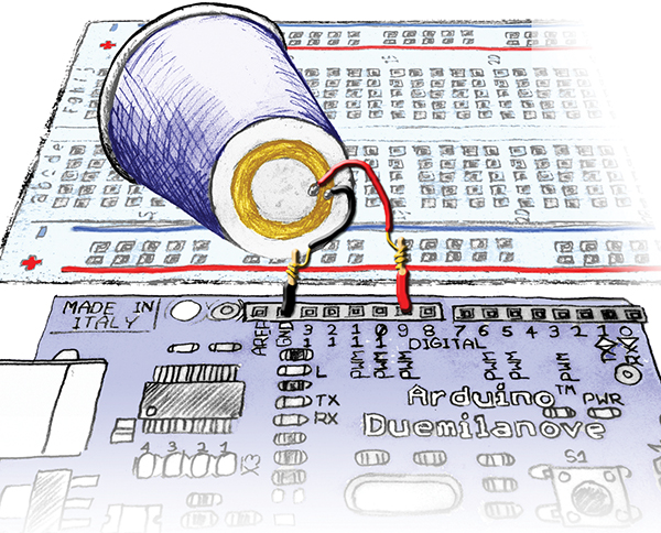 |
| FIGURE 1. ALP with piezo element. |
In Workshop 9, we began using a new development board — the Arduino Duemilanove — recognizing that The Arduino Way (TAW) is a very simple and easy way to begin using microcontrollers. We learned, that while TAW uses a C-like language and has an easy to use IDE, it does not IMHO (In My Humble Opinion) provide a clear path to learning the C programming language or the details of the AVR architecture — both of which are our long-term goals for this Workshop series.
To help overcome this, we learned how to convert TAW code to work with the more standard Atmel AVR tools: AVRStudio, WinAVR, and AVRDude using A C Way (ACW). And, we put together the AVR Learning Platform (ALP) that uses the Smiley Micros Arduino Projects Kit. This will provide our hardware development system for many Workshops to come.
For the next few workshops, we will show the code in (TAW) and leave (ACW) in the associated workshop zip files. After we finish with this introduction to using the kit parts, we will continue the series using ACW since we will want to do things that cannot be easily done TAW (such as using timer interrupts). So, if you are feeling a little confused, that’s a good thing. It means you’ve been paying attention.
In the last episode, we did another communications project, learned to read the voltage across a potentiometer, and then revisited some Cylon Optometry. This time, we are going to develop a command interpreter, and then make some noise.
ALP Number Command Interpreter
In WS12, we learned how to send data from a PC terminal to the ALP to set the brightness of an LED. Let’s expand on that to allow us to send number commands to the ALP and then use those commands to select different functions in our software, specifically, we will use this in a little while to select some tunes. In a later Workshop, we will expand on this so that we can send words not just numbers, and pretend that we are having a natural language conversation with our AVR. We won’t be, but it can get downright spooky how well these things can pretend to be talking to you.
This code is shown here in TAW. The ACW code is in the Workshop13.zip download on the Nuts & Volts website.
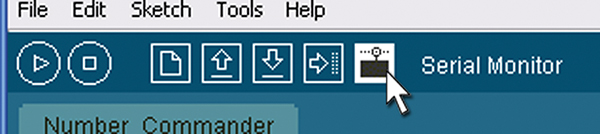 |
FIGURE 2. Select the Arduino IDE serial monitor.
|
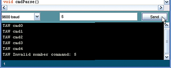 |
| FIGURE 3. Number commander in the serial monitor. |
We will be using the function cmdParse to decide what other functions to call, depending on the user input of a number. The user opens a terminal program, such as the Serial Monitor in the Arduino IDE (Figure 3), and sends a number from 0 to 4 to call one of the cmd#() functions (where # is 0 to 4). Sending any other number will cause the program to send an error message. In this example code, each command function simply sends back a string noting that the command has been received.
[It will probably help if you refer to the source code cmdParse() function in the Number_Commander while reading this paragraph.] Our command parser uses a C programming language switch statement that takes the command number as a parameter and then looks through a list of case statements to find the case corresponding to the command number. For each case, there is a list of things to do if that particular case is the correct one. We use this to call a function associated with the particular command and when the function returns, we call ‘break’ so that the code exits the switch statement (no need to look further down the list since we have already run the case it was looking for). If the switch statement gets to the bottom of the case list and still hasn’t found the correct case, then a ‘default’ case is run which, in our case, tells the user that a bad command was sent and shows the invalid number.
In C, there are two main methods for deciding among a list of possibilities: the switch/case or the if/else constructions. Some folks want to know why C needs both or how to decide when to use which one. If you want to start an argument, bring this up on any C related forum, but my rule of thumb is that if you have fewer than four choices, the if/else will probably be best. If you have four or more, then the switch will probably be best, but the only real way to decide this is to do both and then look at the compiler output and see how it handled it. Different C compilers might handle the same code differently. For our purposes, either way would suffice since we aren’t code size or speed constrained, but I tend to use the switch statement because it just looks better to me.
// Number_Commander TAW<br />
// Joe Pardue May 11, 2009
int cmd = 0;
void setup()<br />
{<br />
  Serial.begin(9600);<br />
}
void loop()<br />
{<br />
  // check if data has been sent from the<br />
  // computer<br />
  if (Serial.available()) {<br />
    cmdParse();<br />
  }<br />
}
void cmdParse()<br />
{<br />
  cmd = Serial.read();
  switch(cmd)<br />
  {<br />
    case ‘0’:<br />
      cmd0();<br />
      break;<br />
    case ‘1’:<br />
      cmd1();<br />
      break;<br />
    case ‘2’:<br />
      cmd2();<br />
      break;  <br />
    case ‘3’:<br />
      cmd3();<br />
      break;       <br />
    case ‘4’:<br />
      cmd4();<br />
      break;<br />
    default:<br />
      Serial.print(“TAW Invalid number command: “);<br />
      Serial.println(cmd, BYTE);<br />
      break;<br />
  }<br />
}
void cmd0()<br />
{<br />
  Serial.println(“TAW cmd0”);<br />
}
void cmd1()<br />
{<br />
  Serial.println(“TAW cmd1”);<br />
}
void cmd2()<br />
{<br />
  Serial.println(“TAW cmd2”);<br />
}
void cmd3()<br />
{<br />
  Serial.println(“TAW cmd3”);<br />
}
void cmd4()<br />
{<br />
  Serial.println(“TAW cmd4”);<br />
}
A few folks have informed me that my Developer’s Terminal is printing in Chinese under some circumstances that I can’t duplicate (at first, I though ‘Chinese’ was just a way of them saying it was random characters, but no, in fact it was Chinese), so check my website to see if this is fixed yet. If not, use either my Simple Terminal or Bray’s Terminal or, as we will do for this example, use the Serial Monitor (as shown in Figures 2 and 3) that comes with the Arduino IDE.
Making Sounds with a Piezo Element
We are advised to make a joyful noise, and what better way than with a piezo element? Well, honestly, just about anything would be better — you don’t get much more low fidelity than this. Even calling the sound it makes ‘noise’ is being generous — so, let’s ask ‘What’s cheaper?’ We are now getting somewhere since these things are cheap and don’t require any external amplification circuitry.
We will listen to high pitched, squeaky renditions of ‘Twinkle Twinkle Little Star,’ ‘Happy Birthday to You’, and a couple of alarms. [WARNING: Only listen to a tune once or twice, or it will get stuck in your head forcing you to listen to an hour of Johnny Rotten just to get it out!]
The piezo element in the Arduino Projects Kit is made from a brass disc with a ceramic disc adhered to it. The brass has the negative (black) wire and the ceramic has the positive (red) wire soldered to it. These wires are stranded and can’t be used directly with a breadboard, so take two pieces of 22 AWG solid wire and solder them as extensions to the piezo wires. (See Figure 1.)
The piezo element warps in response to voltage changes and if this warping is at audible frequencies, you can hear it. I glued (Elmer’s©) the brass side of the piezo to the outside base of a Dixie© cup (one of those small cups you sometimes see in bathroom dispensers). You may be able to hear the sound without the cup, but the cup provides a resonant cavity (or some such techno-buzz words) that mechanically amplifies and directs the sound.
BTW, there are many piezo buzzers out there and they often have special circuitry to create their own buzz, meaning they are either quiet or squalling, but can’t be made to output a specific frequency and are not suitable for this project.
Sound Components, Schematic, and Layout
 |
 |
| FIGURE 4. Piezo sound element. |
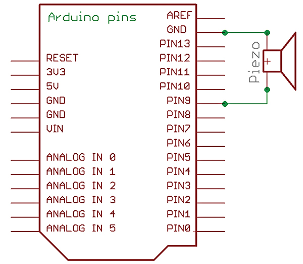
FIGURE 5. Arduino with piezo element schematic. |
The piezo element drawing and schematic symbol from the Arduino Projects Kit are shown in Figure 4; the schematic for the project is in Figure 5; and the layout illustration is in Figure 1.
Tunes
 |
FIGURE 6. Note table.
|
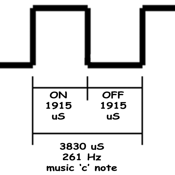 |
| FIGURE 7. ‘C’ note waveform. |
The musical part of the code is based on the Arduino IDE example Melody code written by D. Cuartielles that I expanded to include another tune and some interesting noises. For us to create a recognizable tune, we need to control the musical notes (tones) and the duration between the notes (beat). For simple tunes, we can live with eight tones (a music octave) each having a specific frequency. Each of these tones has a letter ‘note’ assigned to it by musicians as in Figure 6.
We will keep this as simple as possible and generate these notes using the Arduino library delayMicroseconds function. (A microsecond is 1/1,000,000 second — yes: one millionth of a second — you have heard that computers are fast, haven’t you?)
To generate the ‘c’ note, we create an output waveform (see Figure 7) that turns on and off with a frequency of 261 cycles per second. Each of these on/off cycles occurs in 1/261 of a second or 0.003831 seconds. Since we are dealing with microseconds, we multiply this by 1,000,000 to get 3,831 microseconds per cycle. Since we need to cycle the pin (turn the pin on and off) in that time, we turn it on for 3831/2 = 1,915 microseconds (throwing away the fractional part) and off for 1,915 microseconds giving us a total of 3,830. We lost 1 due to our not wanting to use fractions, but who is going to miss a microsecond?
In the Tunes program, we use a playTone function that takes the tone and the duration as parameters. A loop repeats the on/off cycle for the note parameter for a length of time in the duration parameter. It might, for instance, turn the speaker on for 1,915 uS and off for 1,915 uS repeating for a full second to give a rather long ‘c’ note. The playTone function is called by the playNote function that has the job of reading through the tune array to get the next note/duration combination.
Each tune is played by an individual function that contains two arrays: one for the tune notes and one for the tune beat. It calculates the duration from the beats and sends that duration along with the tune note to the playNote function. The playNote function reads through an array of note names and uses that name position in that array to get the number for the microseconds needed to play that note. It then calls playTone with the tone microseconds and the duration as parameters.
The playTone uses those parameters to turn the pin connected to the piezo element on and off, thus generating exquisite music like none heard since the last pterodactyl blundered into a fern tree.
Tunes Source Code
The Tunes source code is shown here in TAW abridged from the full code that is available along with the ACW version in Workshop13.zip. It is shortened since there is a lot of repetition in how the tunes are played. Twinkle, Twerdle, Euro Siren, and Beep Beep are in the zip file. AND a note to more experienced programmers: Yes, I know this isn’t the ‘best’ way to do this, but this is instructional code for novices. I have some comments with the zipped code about better ways and I will show those ways in a future workshop.
/* TAW Tunes<br />
 * Joe Pardue May 13, 2009<br />
 * based on Arduino example code Melody<br />
 * [url=http://www.arduino.cc/en/Tutorial/Melody]http://www.arduino.cc/en/Tutorial/Melody[/url]<br />
 * (cleft) 2005 D. Cuartielles for K3<br />
 */
// define numbers for tunes<br />
#define Twinkle 0<br />
#define Happy_Birthday 1<br />
#define Euro_Siren 2<br />
#define Twerdle 3<br />
#define Beep_Beep 4
// create and intialize global variables<br />
int speakerPin = 9; // pin to drive the piezo element<br />
int tune = 0; // tune to play
void setup() {<br />
  Serial.begin(9600);<br />
  pinMode(speakerPin, OUTPUT);<br />
 <br />
  // greetings<br />
  Serial.println(“TAW Tunes”);<br />
  Serial.println(“Enter 0 for Twinkle Twinkle Little Star”);<br />
  Serial.println(“Enter 1 for Happy Birthday”);<br />
  Serial.println(“Enter 2 for Euro Siren”);<br />
  Serial.println(“Enter 3 for Twerdle Alarm”);<br />
  Serial.println(“Enter 4 for Beep Alarm”);<br />
}
void loop() {<br />
  // check if data has been sent from the<br />
  // computer<br />
  if (Serial.available()) {<br />
    cmdParse(); // if true, get the data and parse it<br />
  }<br />
}
// use a switch statement to decide which tune<br />
// to play<br />
void cmdParse(){<br />
 <br />
tune = Serial.read();<br />
 <br />
  switch(tune){<br />
    case ‘0’:<br />
      play_Twinkle();<br />
      break;<br />
    case ‘1’:<br />
      play_Happy();<br />
      break;<br />
    case ‘2’:<br />
      play_Euro();<br />
      break;<br />
    case ‘3’:<br />
      play_Twerdle();<br />
      break;<br />
    case ‘4’:<br />
      play_Beep();<br />
      break;<br />
    default:<br />
      Serial.print(“TAW Invalid tune: “);<br />
      Serial.println(tune, BYTE);<br />
      break;      <br />
  }<br />
}
void playTone(int tone, int duration) {<br />
  for (long i = 0; i < duration * 1000L; i += tone * 2) {<br />
    digitalWrite(speakerPin, HIGH);<br />
    delayMicroseconds(tone);<br />
    digitalWrite(speakerPin, LOW);<br />
    delayMicroseconds(tone);<br />
  }<br />
}
void playNote(char note, int duration) {<br />
  char names[] = { ‘c’, ‘d’, ‘e’, ‘f’, ‘g’, ‘a’, ‘b’, ‘C’ };<br />
  int tones[] = { 1915, 1700, 1519, 1432, 1275, 1136, 1014, 956 };<br />
 <br />
  // play the tone corresponding to the note<br />
  // name<br />
  for (int i = 0; i < 8; i++) {<br />
    if (names[i] == note) {<br />
      playTone(tones[i], duration);<br />
    }<br />
  }<br />
}
//Happy Birthday<br />
int Happy_length = 26; // the number of notes<br />
char Happy_notes[] = “ccdcfeccdcgfccCafedbbafgf “; // a space represents a rest<br />
int Happy_beats[] = { 1, 1, 2, 2, 2, 4, 1, 1, 2, 2, 2, 4, 1, 1, 2, 2, 2, 2, 6, 1, 1, 2, 2, 2, 2, 4 };<br />
int Happy_tempo = 150;<br />
void play_Happy(){<br />
  for (int i = 0; i < Happy_length; i++) {<br />
    if (Happy_notes[i] == ‘ ‘) {<br />
      delay(Happy_beats[i] * Happy_tempo);<br />
    // rest<br />
    } else {<br />
      playNote(Happy_notes[i], Happy_beats[i] * Happy_tempo);<br />
    }<br />
    <br />
    // pause between notes<br />
    delay(Happy_tempo / 2);  <br />
  }  <br />
}
Well, that’s all the room for this month. Next month, we will look at the Arduino Projects Kit light and temperature sensors along with some coding techniques for presenting fractional values of data without having to store fractions. NV
You can find the source code and supplements for this article in Workshop13.zip in the downloads section of the Nuts & Volts website and Smiley Micros website.
The Arduino Projects Kit
The Arduino projects kit is a special hardware pack that will help you get hands on experience as you follow along with this series. It provides components for use with Workshops 9, 10, 11, and many future Workshops. Over time, we'll learn simple ways to use these components, and more importantly, use them to drill down into the deeper concepts of C programming, AVR microcontroller architecture, and embedded systems principles.
The Arduino Projects kit is offered through the Nuts & Volts webstore and Smiley Micros website.
Back to top
Downloads
Smiley’s Workshop 200905 (Workshop13.zip)