Smiley's Workshop — AVR C Programming Workshop Series - Part 17
This is the last of the introductory Arduino Projects Kits Workshops.
Recap
 |
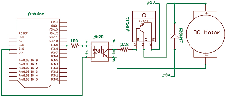
| FIGURE 1. Simple motor speed control. |
We’ve covered all sorts of things from ‘why asking for Arduino in Milan will get you directions to a local pub,’ to ‘why bunny rabbits shouldn’t back into dark places.’ We’ve even learned a few technologically relevant things that will help us get going with a lot of projects we might want to do with a microcontroller, from blinking an LED to counting tomato soup cans using the Arduino Duemilanove and the Arduino Projects Kit. Last time, we tied up some loose ends concerning interrupts, getting numbers from a PC, and optical isolation. So now, let's tie it all together and learn to do some simple motor control.
How Our DC Motor Works
In Figure 2, we see a simplified drawing showing how a DC motor runs. There are three main components:
- Stator
- Rotor
- Commutator
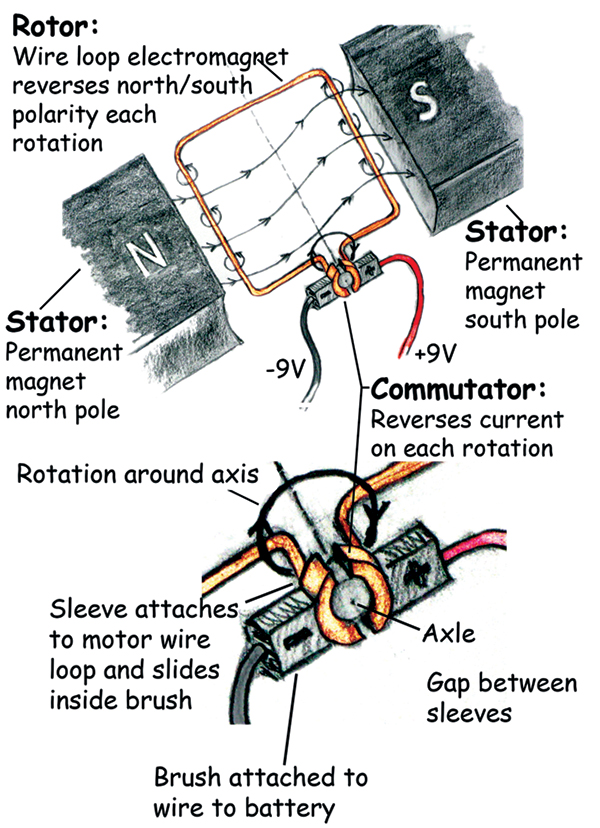 |
| FIGURE 2. DC motor principles: We see a simplified drawing showing how a DC motor runs. There are three main components. |
The stator (as shown here) is a pair of permanent magnets that don’t move (static). The rotor is a loop of copper wire forming an electromagnet that — wait for it — rotates. The commutator is a clever little mechanical device that takes the ends of the loop and flattens them on a cylindrical sleeve over the axle so that they have a gap between them (preventing the ends from short-circuiting. One end of the loop wire goes on one side of the sleeve and the other end goes on the other sleeve so that they can slide under the brushes. In the figure, the electromagnet is shown aligned with the permanent magnets, but the electromagnetic field is aligned in the opposite direction, causing the distortion in the permanent magnetic field. This means that the part of the loop to the left is the electromagnetic north and attracted to the south pole of the permanent magnet on the right, and the right side of the loop is south and attracted to the north magnet. So, the magnetic attraction/repulsion causes the loop to turn in the clockwise direction. But look what happens to the loop end sleeves on the commutator as the loop turns. The loop end that was touching the negative electric brush rotates away and comes in contact with the positive electric brush while the end that was touching the positive brush now contacts the negative brush. The current reverses in the loop causing the electro magnetism to reverse; the side that was attracted to the south magnetic pole is now attracted to the north magnetic pole. The rotation continues on around clockwise pulled by the magnetic forces until the loops nearly attain their desired goal. But the commutator again causes the current, and thus the magnetic attraction to reverse, keeping the loop spinning about the axle. For some reason when I was writing this, I began to wonder if maybe youthful romance doesn’t have some sort of commutator that causes attraction to opposites until they get near, then find themselves repulsed and attracted to the other opposite and so on, until their axle wears out (followed by marriage, kids, debt, attempts to lube the commutator, overheating, short-circuits, nursing home …).
 |
 |
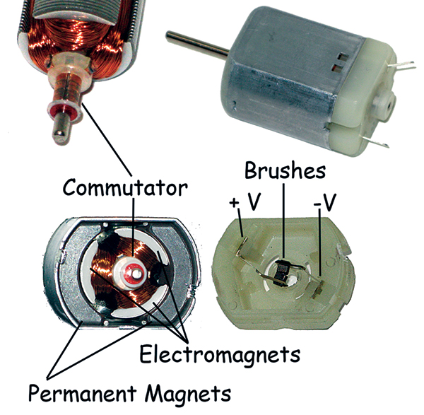
| FIGURE 3. DC motor dismantled. |
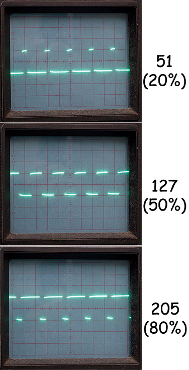
FIGURE 4. PWMs on an oscilloscope. |
 |
| FIGURE 5. Diode. |
While this description does cover the principles of DC motors (and romance), it oversimplifies both. The commutator as drawn will short-circuit once each turn when the gaps are under the brushes. The actual motor we are using (Figure 3) has a three point commutator with three iron posts for the winding which not only prevents the short, but makes for better sequencing of the magnetic attractions/repulsions. (I’ll forbear any more romantic metaphors, though there is often a third party involved).
Powering the Motor
The motor in the Arduino Projects Kit is designed to run from six to 15 volts (nominal 12 volts, but nine volts is fine for our purposes) and 110 milliamps. There is a lot of slop in these figures. You can get it to turn with lower voltage or current, and it will spin happily at higher voltages or currents. Below a certain value, however, it won’t turn and above a certain value it will heat up and something will break. We will use our battery as a constant (more or less) voltage source, and control the motor speed by pulsing the current with a transistor.
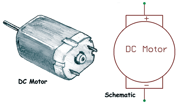 |
| FIGURE 6. DC motor. |
Every explanation I’ve read about how transistors work has either been too simple or too complex, so let’s just accept that a tiny current on the base pin controls a much larger current between the collector and emitter pins (Figure 7).
 |
| FIGURE 7. Power transistor. |
Using PWM to Control the Motor Speed
We will use a Pulse Width Modulation (PWM) signal transmitted from the Arduino through an optoisolator to the base of our TIP115 transistor to make or break the connection to our nine-volt battery.
The Arduino analogWrite() function produces a PWM signal with a frequency of about 490 Hz (on/off periods per second). During each of these periods, the signal can be turned on for a part of the period and off for a part of the period. The on/off time is called the duty cycle and it can vary from 0 (fully off) to 255 (fully on), with increments in between such as 127 which sets it on half the time and off half the time (50% duty cycle). As you can see from Figure 4, a value of 51 sets a 20% on time for each of the cycles, and a value of 205 sets an 80% on time for each cycle. The motor (Figure 6) will run slower at a low duty cycle and faster at a high duty cycle, but the relative speeds are not directly proportional to the duty cycle. You need a minimum duty cycle to provide enough energy to get the motor going — in my case, sending analogWrite() a value below 25 wouldn’t make it run.
 |
|
FIGURE 8. Motor speed control schematic.
|
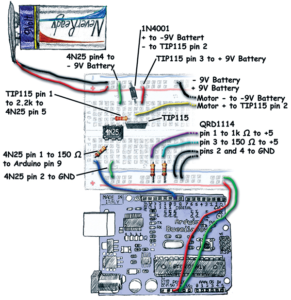 |
| FIGURE 9. Motor speed control layout. |
The point to take away is that you can’t know the motor speed just from the duty cycle you are generating. You have to actually measure the speed and then adjust the duty cycle to fit the speed you require. We’ll do this in a moment reusing the IR Detector Interrupt code from WS16. First, build the circuit shown in Figure 8 and Figure 9. Test this circuit with the Arduino Fade example (discussed in WS10). If you hold the motor, you should feel it speeding up and slowing down to the same timing as the LED brightening and fading.
Diode to Suppress Voltage Spikes
The process involved in making the motor turn also causes the current to reverse in the copper windings every turn. One notable characteristic of coils of wire (like in the motor windings) is that once the current has started flowing, it doesn’t want to stop. If you try to stop the current by cutting the wire, the current will ‘pile up’ on one side of the cut creating a high voltage that can drive the current through the air across the cut as a spark. In the motor, the current must not only stop, it must reverse directions for each turn of the motor. This stop and reversal process generates high voltage spikes for each revolution of the motor and while an isolated motor can handle this with no problems, the voltage spikes can wreak havoc on other devices that share the same power supply. The diode shown in Figure 8 acts like a one-way valve (as shown in Figure 5) so that when the current is flowing in the proper direction, the valve is off; when the current backs up, the valve opens to let it drain off the reverse surge.
Building the Breadboard Circuit
This is the most complicated circuit we will be building using the Arduino Projects Kit and, frankly, the chances of building the full circuit and writing the code from scratch and having it work correctly the first time are almost nil. You should think of this as being built from hardware/software sub-components that we’ve done before. First, make sure the IR detector is working properly (built and tested in WS15), and then make sure the optoisolator is doing what it should be doing (built and tested in WS16). Next, we add the TIP115 (Figure 7) to the optoisolator circuit in place of the LED and test that the motor speed varies in sync with the LED brightness. Only after you are sure that each part is working properly should you put the encoder wheel on the motor and try to use it to control the motor speed. This is a breadboard and something will go wrong; be prepared to take small steps and when something does go wrong, be willing to back up and verify each part of the whole.
Please note that the photograph in Figure 1 shows the power on the opposite end of the breadboard than what is shown in Figure 9. I did this to simplify the circuit by showing it isolated and not mixed up with the IR detector circuitry. It shouldn’t matter where you put either, as long as the QRD1114 is sticking out over the end of the board close to the encoder wheel.
Using an Encoder Wheel to Measure the Motor Speed
 |
FIGURE 10. Encoder wheel.
|
We will reuse the IR reflective sensor circuit from Workshop 15 and the interrupt software from Workshop 16 to count the passing of the stripes on the encoder wheel shown in Figure 10. Download the pdf file of the image (Workshop17.zip) and print it on plain paper with an inkjet printer, for better IR reflectivity; darken the black stripes where they will be in front of the QRD1114 using a Sharpie© pen. Paste the disk on a piece of cardboard.
When it is dry, make a hole for the motor axle by using an X-acto knife or a scalpel (or whatever very sharp pointed thing you have handy), then slice a few 1/8” cuts in the form of an asterisk (*) at the center point of the wheel. In my case, I could slip the wheel on the motor axle and there was enough pressure provided by the cardboard to hold it in place. If yours is loose, you might want to add a touch of glue — after you’ve made certain that the disk is both flat and at a 90° angle to the axle. You might let the glue get tacky, then run the motor while it finishes drying as the centrifugal force will align the disk properly. Play with it since a little wobble won’t hurt, but a lot may make the QRD1114 readings unreliable. The motor stand was cut out of foamcore board and stuck together using masking tap and hot-glue. I eyeballed the measurements and trust that by looking at Figure 1, you can too.
Simple Motor Speed Control with Digital Feedback
The program Simple_Motor_Speed_Control uses principles discussed in earlier Workshops (9 to 16). To set the speed, you enter a number followed by an ‘!’. This number will be compared to the count from the encoder wheel spinning in front of the IR detector. If the actual count is lower than the input value, then the value being sent to the PWM by analogWrite(value) will be incremented by the amount in the constant ADJUST (five, in this case). If the count is greater than the input number, the value will be decremented.
 FIGURE 11. Program serial I/O. FIGURE 11. Program serial I/O. |
You can find the maximum and minimum input values by experimenting. I noted that values of less than 125 caused the motor to stop and values greater than 1,050 maxed out the PWM value. Figure 11 shows that entering a value of 200 for the ‘Input’ when the ‘Count’ is 596 causes the ‘Speed’ to decrease by five each second. When the count is close to the input, the speed will increase and decrease each second to keep the count close to the input. Even though the hardware and software are ‘simple,’ it serves to show the basic principles involved for one method of motor speed control.
// Simple_Motor_Speed_Control 8/13/09 Joe Pardue<br />
// This program is based on other<br />
// Arduino code discussed in<br />
// Smiley’s Workshops 9 through 16.
#define ADJUST 5 // speed +or-
// variable to keep PWM value<br />
int value = 0;<br />
// pin for motor PWM signal<br />
int motorpin = 9;
// variables for serial input<br />
int myInput = 0;<br />
int myNum[6];<br />
int myCount = 0;
// always declare interrupt variables<br />
// as volatile<br />
volatile int count = 0;
// serial input converted to integer<br />
int input = 0;
// value for PWM<br />
int speed = 0;
// time keeping<br />
long oldTime = 0;<br />
long newTime = 0;
void setup()<br />
{<br />
   Serial.begin(9600);<br />
   Serial.println(“Simple_Motor_Speed_Control”);<br />
   <br />
  // attach interrupt 0 (pin 2) to the<br />
  // edgeDetect function<br />
  // run function on falling edge interrupt<br />
  attachInterrupt(0,edgeDetect, FALLING);<br />
 <br />
  oldTime = millis();<br />
}
void loop()<br />
{<br />
  newTime = millis();<br />
  if(newTime > (oldTime + 1000))<br />
  {<br />
    oldTime = newTime;<br />
    Serial.print(“Count: “);<br />
    Serial.print(count);<br />
    Serial.print(“ Input: “);<br />
    Serial.print(input);<br />
    Serial.print(“ Speed: “);<br />
    Serial.print(speed);<br />
    Serial.println();<br />
    <br />
    if( (speed >= 0)&&(speed<=255) )<br />
    {   <br />
      if(count < input)<br />
      {<br />
        if (speed != 255)<br />
        {<br />
          speed += ADJUST;<br />
        }<br />
      }<br />
      else<br />
     {<br />
       if (speed != 0)<br />
       {<br />
         speed -= ADJUST;<br />
       }<br />
     }<br />
     analogWrite(motorpin, speed);<br />
    }<br />
    else (speed = 0);
    count = 0;       <br />
  }<br />
      <br />
  getNum();<br />
  if(myInput == ‘!’)<br />
  {<br />
    // convert end-of-number character ‘!’ to 0<br />
    myInput = 0;<br />
    myNum[—myCount] = 0;<br />
 <br />
    // convert ASCII string to<br />
    // integer<br />
    input = ATOI();<br />
 <br />
    // map the count number to the PWM value<br />
    Serial.print(“input: “);<br />
    Serial.println(input,DEC);
    // clean up and do it all<br />
    // again<br />
    clearAll();<br />
  }<br />
}
// Put serial characters in a character array<br />
void getNum()<br />
{   <br />
  if(Serial.available())<br />
  {  <br />
     myInput = Serial.read();<br />
     // put the character in the array<br />
     myNum[myCount++] = myInput;  <br />
  }    <br />
}
int ATOI()<br />
{    <br />
  // algorithm from atoi() in C standard library   <br />
  int i = 0;<br />
  int n = 0;<br />
  for(i = 0; myNum[i] >= ‘0’ && myNum[i] <= ‘9’; ++i)<br />
    n = 10 * n + (myNum[i] - ‘0’);
  return(n);  <br />
}
void clearAll()<br />
{<br />
  int i;<br />
 <br />
  myCount = 0;<br />
  for(i = 0; i < 6; i++)
  {<br />
    myNum[i] = 0;<br />
  }<br />
  Serial.flush();  <br />
}
// On each IR detector interrupt<br />
// increment the count<br />
void edgeDetect()<br />
{<br />
  count++;<br />
}
Well, that’s it for this series on the Arduino Projects Kit used the Arduino Way. Tune in next month for more fun with AVR microcontrollers. NV
You can find the source code and supplements for this article in Workshop17.zip in the downloads section of the Nuts & Volts website and Smiley Micros website.
The Arduino Projects Kit
The Arduino projects kit is a special hardware pack that will help you get hands on experience as you follow along with this series. It provides components for use with Workshops 9, 10, 11, and many future Workshops. Over time, we'll learn simple ways to use these components, and more importantly, use them to drill down into the deeper concepts of C programming, AVR microcontroller architecture, and embedded systems principles.
The Arduino Projects kit is offered through the Nuts & Volts webstore and Smiley Micros website.
Back to top