Smiley's Workshop — AVR C Programming Workshop Series - Part 8
In Part 6, we used the Butterfly joystick with library functions to implement a menu navigation system but didn't go into any details of how the joystick worked. This time, we will use the joystick as an introduction to AVR interrupts and I/O registers.
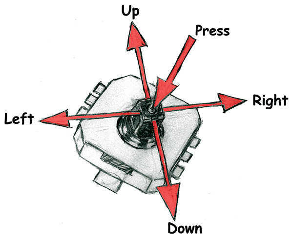 |
FIGURE 1. Butterfly joystick with five button positions.
|
The Butterfly Joystick Hardware
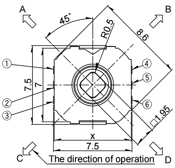
The original joystick was an early aircraft control lever that allowed the pilot to maneuver the plane left, right, up, and down. Fighter planes added a center button to fire machine guns. The Butterfly joystick — like many menu navigation devices found on remote controls and cell phones — has five positions: UP, DOWN, LEFT, RIGHT, and PUSH (see Figure 1). Manufacturers, of course can't know which direction the user will orient their device, so they label them A, B, C, D, and Center (for PUSH) as in Figure 2, which correspond to pins numbered as in Figure 3.
 |
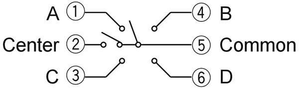 |
| FIGURE 2. Joystick schematic. |
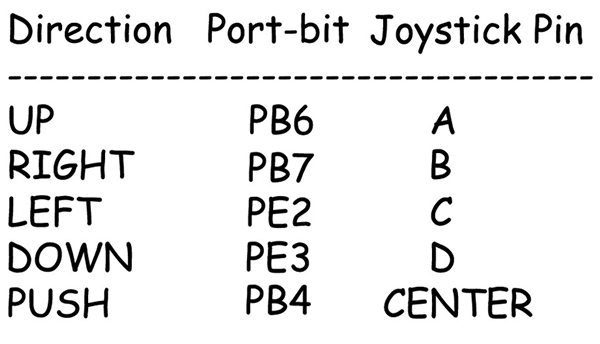 |
FIGURE 3. Joystick mechanical drawing.
|
FIGURE 4. Butterfly joystick pins.
|
The Butterfly orients these pins and connects them to five of the ATmega169 port pins as in Figure 4.
Now that we've got the joystick all wired up, how does the Butterfly know when a joystick event occurs?
Interrupts In General
In microcontrollers, we typically use either polling or interrupts to check to see if an event has occurred. Polling checks periodically to see if an event has happened. For instance, in the loop in main() we might check pin 6 to see if the voltage is +3 or 0 and, depending on the state, do one thing or another. If the microcontroller hardware is designed so that pin 6 can be used to interrupt the program, then we don't have to poll the pin. We can set the software so that when the pin state changes — say, falling from +3V to 0V — an interrupt function will be called automatically.
Interrupts on microcontrollers are like interrupts in daily life. The telephone interrupts your activities by its insistent ringing. Imagine how it would be if you had to poll the telephone to receive calls. Periodically, you'd pick up the receiver and say 'Hello, anybody out there?' and your caller would shriek, 'I've been waiting for an hour! Why don't you check your phone every five minutes like a normal person?' The ring of the phone interrupting workflow is annoying, but if someone wants to tell you that your garage is on fire, you want to know about it immediately.
Microcontrollers respond to interrupts much like you would. Maybe you are reading a book and the phone rings. You use your fingernail to mark the line you were reading and dog-ear the page before closing the book (librarians everywhere groan). Then, you answer the phone, and when the call is finished and you've put out the fire in your garage, you can refer to the desecrations to your book and go right back to where you left off.
From the hardware perspective, an interrupt causes the microcontroller to stop what it is doing, store sufficient data so that later it can get back to what it was doing, look to see which interrupt happened, run the interrupt code, and when finished, restore the machine to its state before the interrupt occurred using the previously stored data.
Potential Interrupt Bug 1
Interrupts are great, but they provide an avenue for some particularly pernicious bugs. For example, your code is reading an integer from memory; an integer is made of two bytes. The code gets the first byte, then is stopped by an interrupt that changes the value of that very same integer before returning control to the part of the code that was reading it, which then gets the second byte of the integer. The integer will be wrong because it is made from half of the pre-interrupt value and half from the post-interrupt value. The crazy-making debugging problem is that the interrupt can happen at any time; maybe only rarely during the integer read. Your system can run like a champ and then lock up for no apparent reason. You don't want this kind of bug in your pacemaker. So you prevent it by disabling interrupts before reading variables that can be changed by interrupts, and then re-enabling them after you've got the correct number.
Potential Interrupt Bug 2
Another problem with interrupts changing variables can occur when you have the variable in a section of your code that looks to the compiler optimizer like it is not being used. The optimizer has various rules to search around to see if a variable is used, but it may not have a rule to look at the interrupt service routines to see if the variable is used there. If it doesn't look there, then it may reasonably decide that you made a mistake and aren't really using the variable, and then optimize it away in the code generated from the C source code. This can cause another tricky bug since that variable is in your source code and you may not realize that the optimizer got rid of it. To prevent this error, you should declare all variables that will be changed by an interrupt as 'volatile' which tells the compiler that — with all evidence to the contrary — you actually know what you are doing so don't get rid of this volatile variable.
C Knows Nothing About Interrupts
It is important to realize that the C programming language knows nothing about interrupts. C is machine independent — interrupts are machine dependent. Even different versions of the same machine — such as the AVR — may handle interrupts differently. Also, different compilers for the same microcontroller will often have different ways to use interrupts. We are fortunate to have the free WinAVR tool set with the GCC avrlibc to handle some of the more gory details, though it will get pretty gory anyway.
A Quick Look At Registers
The AVR is a very flexible device and many of its features have several different ways they can be used. For instance, the ATmega169 I/O pin that we will be using for our UP selection in the joystick can be set up to be used in one of various ways: as either input or output; with or without an internal pull-up; it can be turned off (tri-stated) to remove it from the circuit or work for PWM output compare; or it can be used as an input interrupt. Other pins may be even more complex in their possible uses, but since each can only be used in one of its many possible configurations, the AVR must keep track of how it is supposed to be used. Setting bits in a special set of I/O registers to configure and keep track of various possible states does this.
AVR registers are eight bit memory locations that can be quickly accessed by the CPU. The AVR sets aside 64 I/O and 160 Extended I/O Registers in memory locations that can be used for peripheral configuration and state flags. The ATmega169 uses over 100 of these registers. Each of these registers is named and may have two to eight named bits for each. As usual for microcontrollers, the names may be cryptic and confusing. This provides us with a bewildering excess of riches. You can see the list on page 341 of the ATmega169 data book — pretty scary, isn't it? But, relax because we won't have to memorize any of the details. Over time, we will carefully set up each register only when it is needed for a particular application and once we get that AVR feature working properly, we will consign the register and bit states to header files hidden behind some easy to remember names — well documented and carefully locked away in a tested library. The earlier Workshops hid all this in libraries, and there will be many libraries to come. In the meantime, it will help us to understand what is going on if we get an overview of this I/O register/bit concept.
Setting Up External Interrupts Using The ATmega169 And avrlibc
To enable the joystick interrupts, we will need to set bits in four registers. We will see how to do this for three progressively simpler ways. The first is the most like a professional C programmer would do it — using the datasheet acronyms and bitwise operators which can be a bit cryptic for a novice. The second is a little simpler and hides the bitwise operations behind a macro. The third and simplest expands the acronyms to spell out the full register and bit names. In this Workshop, we will show the details only for the EIMSK (External Interrupt Mask Register), but the source code shows this for all used interrupts.
External Interrupt Mask Register
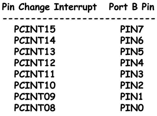 |
| FIGURE 5. Associating pin change interrupts with port B pins. |
We set the PCIE0 and PCIE1 (Pin Change Interrupt Enable 0 and 1) bits to enable PCINT15..8 which are the upper eight Pin Change Interrupts and are associated with the Port B pins 7..0 in the ATmega169 as shown in Figure 5.
The first way to do this is to use the register and bit acronyms listed in the io.h header file:
// Least verbose - most usual C like<br />
EIMSK = (1<<PCIE0) | (1<<PCIE1);
If you remember the bitwise operators from Workshop 4 and know that in the header file that PCIE0 is defined as 7 and PCIE1 is defined as 6, you will see that this sets bit 7 and bit 6 in the EIMSK register. This register is shown on page 78 of the ATmega169 datasheet (see Figure 6).
 |
| FIGURE 6. The EIMSK Register. |
A slightly easier way would be to define a macro for the bit shift operators to set the bits:
#define setBit(value1,value2) value1 |=(1<<value2)
A macro is a preprocessor directive that causes the “compiler to substitute one set of characters with another set. This can help simplify things in that you can substitute a simpler string of text for something more difficult. We can hide the bitwise operators that shift and the OR bits.
Anywhere the compiler sees:
setBit(value1,value2)
It will substitute:
value1 |= (1<<value2)
For instance, if we use:
setBit(EIMSK,PCIE0)
The compiler will write:
EIMSK |= (1<<PCIE0)
Finally, we will try to make this even easier by expanding the acronyms:
#define ExternalInterruptMaskReg EIMSK<br />
#define PinChangeInterruptEnableBit0 PCIE0<br />
#define PinChangeInterruptEnableBit1 PCIE1
and using:
// Most verbose<br />
setBit(ExternalInterruptMaskReg,<br />
    PinChangeInterruptEnableBit0);
setBit(ExternalInterruptMaskReg,<br />
    PinChangeInterruptEnableBit1);
You can see how this is done for all five registers by looking at the initJoystick() function in the source code in the Workshop8.zip (refer to the download link at the end of this column.)
Enable Global Interrupts
SREG — Status Register
I-bit — Global Interrupt Enable
Setting the I-bit enables all interrupts and clearing it disables them. After a hardware interrupt occurs, the I-bit is cleared so that no further interrupts can occur while the interrupt service routine is running. When the interrupt finishes, the interrupt returns with the RETI instruction that will reset the I-bit, thus enabling further interrupts.
External Interrupt Flag Register
EIFR — External Interrupt Flag Register
PCIF0 — Pin Change Interrupt Flag 0 Bit
PCIF1 — Pin Change Interrupt Flag 1 Bit
If PCIF0 is set, when any PCINT7..0 pin changes state and if the I-bit is set and the PCIE0 bit is set in EIMSK, then an interrupt request is triggered so that the associated interrupt service routine will be run. The same is true for the PCIF1 bit and the PCINT15..8 pin changes.
Pin Change Mask Registers
PCMSK0 — Pin Change Mask 0 Register
PCMSK1 — Pin Change Mask 1 Register
The PCMSK0 register has PCINT15 to PCINT8 bits, each of which when set to 1 enables the pin change interrupt for the corresponding I/O pin.
Interrupt Service Routines
When the ATmega169 receives an interrupt, it loads the address of an Interrupt Service Routine from the Interrupt Vector Table. A 'vector' is just a fancy way to say address. There are 23 vectors shown on page 47 of the datasheet but we will only be using vectors 3 and 4 for the PCINT0 and PCINT1 interrupt.
// Pin Change Interrupt 0<br />
// Interrupt Service Routine<br />
ISR(SIG_PIN_CHANGE0)<br />
{<br />
    pinChangeInterrupt();<br />
}
// Pin Change Interrupt 1<br />
// Interrupt Service Routine<br />
ISR(SIG_PIN_CHANGE1)<br />
{<br />
    pinChangeInterrupt();            <br />
}
So, if any of the joystick pins change then the pinChangeInterrupt() function will be called by ISRs. When an interrupt is triggered, the I-bit is cleared and no further interrupts will be serviced until the ISR exits — so interrupts should to be serviced as rapidly as possible (there are exceptions, but we won't deal with those yet). If the interrupt requires some serious processing to be done, just set a flag, exit the interrupt, then look for the flag in the infinite loop in main() and call a regular function that can be interrupted.
Servicing The Joystick Interrupt
In the pinChangeInterrupt() function, we will not use any simplifying macros. We first load the ports B and E pin pattern into an eight-bit variable:
uint8_t buttons;
buttons = (~PINB) & PINB_MASK;<br />
buttons |= (~PINE) & PINE_MASK;
Note that the pin state is 0 for the pin that got changed. The PINB_MASK makes sure that only valid joystick pins are looked at and PINB contains the state of the pins on port B. Since we are ANDing it with the mask, we use the ~ operator to invert the levels, changing 0 to 1. You may want to review bitwise operators in Workshop 6 and do a little pencil and paper computing if this isn't clear.
After we get the pin states in the button variable, we check for the key:
// Which key was pressed?<br />
if (buttons & (1<<BUTTON_A))<br />
    key = KEY_UP;<br />
else if (buttons & (1<<BUTTON_B))<br />
    key = KEY_DOWN;<br />
else if (buttons & (1<<BUTTON_C))<br />
    key = KEY_LEFT;<br />
else if (buttons & (1<<BUTTON_D))<br />
    key = KEY_RIGHT;<br />
else if (buttons & (1<<BUTTON_O))<br />
    key = KEY_PUSH;<br />
else<br />
    key = KEY_INVALID;
If there is a valid key present, we load it in the global joystickInput variable and set the global joystickChanged to true:
// Is there a valid key?<br />
// Load it in the global variable joystickInput<br />
// And set the global variable joystickChanged<br />
if(key != KEY_INVALID)<br />
{<br />
    joystickChanged = 1;<br />
    joystickInput = key;<br />
}
This works much like the Menu in Workshop 6, but this time we hide the state machine in a library and show the joystick hardware setup and use. You can download the source code and a supplement: C Programming — Out of the Nest in the downloads section of this article's page at www.nutsvolts.com or www.smileymicros.com. NV
Downloads
Smileys Workshop 200903 (workshop8.zip)