Smiley's Workshop — Serial Communications - Part 1
Communications Between A PC And A Microcontroller.
Recap
In our last episode of Smiley's Workshop, we finished with our introduction to the Arduino Projects Kit and used all the parts to do some interesting things. This time, we will start to look a bit deeper into communicating between the Arduino and a PC and we'll begin a three-part series about serial communications between a PC and a microcontroller. In the first part, we will learn a bit about the virtual serial port used in the Arduino and introduce writing programs on the PC using the free Microsoft C# and Visual Basic Express .NET applications. We’ll use this to build Graphical User Interfaces (GUIs). Next time, we'll apply this knowledge to build a Simple Terminal program. In the third part, we'll build a GUI for an Arduino VoltMeter.
Virtual Serial Port Introduction
Why Imitate a PC Serial Port with USB?
In the old days, the PC serial port had a Windows© driver and hardware link based on the RS-232 electrical specification, and used a DB-9 connector and a UART (Universal Asynchronous Receiver Transmitter). It wasn’t exactly simple for a novice PC user to hook up a serial link since it required the user to select software interrupts and set hardware jumpers — something you and I as certifiable nerds like to do, but something that normal people hate and tend to mess up. These and other complications led to the development of the Plug and Play initiative (more commonly and correctly known as Plug and Pray). One part of all this was to replace the serial port with USB to help simplify things. This helped the user, but made the developer’s life much more complicated. Lots of perfectly good serial devices and a couple of decades of knowledge of how to do robust RS-232 style serial communications between PCs and external serial devices were made obsolete by USB.
I’ve read the USB specification, and I’m here to testify (brother, amen) that the old ComPort/UART/RS-232 was a piece of cake compared to USB. I worked with USB when it first came out and my brain is definitely worse for the wear. Fortunately, some really smart people created a transitional concept: to have an old fashioned RS-232 style serial port that runs over USB. The FTDI folks call this a Virtual Communications Port (VCP). It allows legacy applications to continue to use the old microcontroller code and the Windows COM port software with the USB part. This is all tidily bound up in a black box that the developer doesn’t have to open. These transitional devices give us the best of both worlds: the ease of using the serial (COM) port and the ubiquity of using USB. The developer has the option of adding RS-232 level converts to completely emulate the old way of doing things, or leaving the level converters off and outputting voltage levels directly compatible with a microcontroller’s UART. The latter is exactly what the Arduino does to allow serial communications with a PC.
The FTDI chip (FT232R) used on the Arduino is the same as that used on the BBUSB that was discussed in detail in the article “The Serial Port is Dead, Long Live the Serial Port’ by yours truly in the June ‘08 issue of Nuts & Volts. You can also get the book Virtual Serial Programming Cookbook (also by yours truly) and an associated projects kit from either Nuts & Volts or Smiley Micros. Much of the information in this article on using C# and VB for serial communications is derived from that book.
Why Communicate With a PC?
A microcontroller is used to control something. The something could be the ignition timing on your car, the water temperature in your washing machine, the obnoxious tune (that you think is cute) on your cell phone, etc., etc., etc. The word ‘ubiquitous’ seems almost invented to describe the current uses of microcontrollers; they really are everywhere.
Most often, the microcontroller knows how to do its job and doesn’t need any advice from you. If it does deign to accept suggestions, you usually give them via a button (snooze alarm) or touch pad (microwave oven). Some of us — mostly students, hobbyists, and developers — want to spend a lot of time in conversation with a microcontroller, however. This may be because we want to learn how it works; get it to follow complex commands that aren’t easy to give with buttons; or because we are designing a complex system and we need direct access to the micro’s brains while we are figuring out why things aren’t working like they are supposed to. If you are one of these folks, then you might see the benefit of being able to use the vast resources of a PC to talk to your microcontroller. We will look at some things to help you to do this.
Why Use C# and Visual Basic Express .NET?
One good reason for selecting either language in Express .NET is because both are free. (You like free, don’t you?) I decided to present the software in both C# and Visual Basic Express.NET because there are lots of folks who program in one language and think the other language is the vile realm of hell-bound heretics. However, the concepts are the same no matter what language is being used (religious wars aside). Examples are done in both languages with the C# example shown here, and the Visual Basic example included in the Workshop18.zip. Just skip over the language you don’t like.
You will find a treasure trove of free tools and learning materials at www.microsoft.com/express. If you are entirely new at programming GUIs (pronounced gooey) on Windows, then I’d suggest that you use C#, since it’s similar to C and is most likely the language you will choose for the other side of the cable — the microcontroller. If you are already a Basic fan or have used VB on a PC, then you will probably want to use the Visual Basic Express. Be prepared for a lot of culture shock, however.
The IDE shown in many of the illustrations here will be for C#; the Visual Basic IDE is virtually identical, so it shouldn’t be difficult to transpose the concepts.
As I stated before, the Microsoft learning resources are really great and free. For our purposes, you don’t need to view all the lessons, just the introductory materials, plus the parts on forms and common controls. Keep in mind the ultimate goal: We are learning to use tools that will allow us to build GUIs on a PC that we can use to communicate with microcontrollers connected to either a real serial port or a USB virtual serial port.
Once you’re comfortable with building simple forms with textboxes and buttons, you are ready to look at the Simple Terminal software source code. Pay careful attention as we go through the steps to create this program. Before we write it, let’s play with the finished version to get some insight into where we are going once we actually write the code.
Running the Simple Terminal
The Simple Terminal is available in two forms: first is a publish version that allows you to install and run the program on your PC; the second version is the source code that loads in Visual Studio Express .NET.
The Workshop18.zip includes:
- ..\Simple Terminal Application
- ..\Arduino Command_Demo
- ..\SimpleTermGUI_C#_Source
- ..\SimpleTermGUI_VB_Source
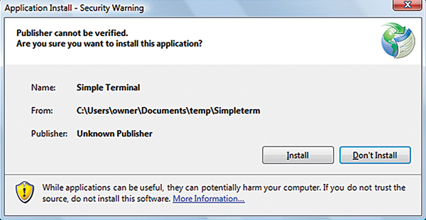
Unzip it and open the Simple Terminal Application directory; then click on the setup application. You will see the warning shown in Figure 2. Click Install if you are using Vista (cuss it out if it asks you if you are sure). It should open and look like Figure 1, except that the text boxes should be empty.
 |
 |
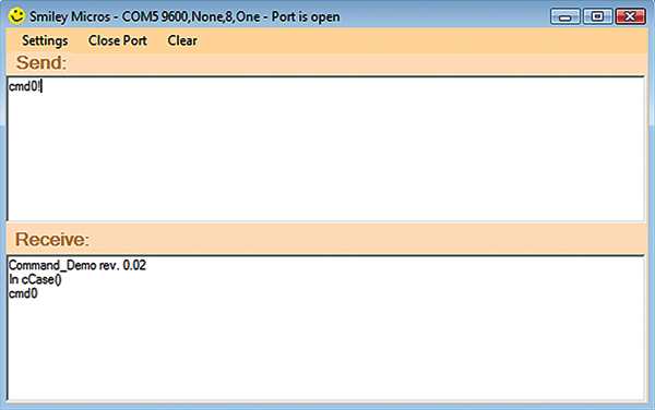
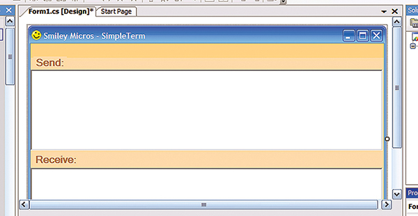
| FIGURE 1. A Simple Terminal. |
FIGURE 2. Yet another bogus warning. |
Click on the ‘Settings’ menu item. In the Settings dialog, click the COM port connected to the Arduino as shown in Figure 3. In my case, the only port available is COM5. Your Arduino will probably be on a different port, so click on that one. Make sure the serial port you selected shows up in the Serial Port label. If you don’t click it, then the port defaults to COM1. The Arduino Command_Demo that we will be using has a baudrate set to 19200, which is the default for the Simple Terminal. You should now click ‘Okay.’
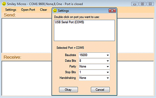 |
| FIGURE 3. Settings. |
Next, open the Arduino Command_Demo directory on your PC and then upload the Command_Demo program into the Arduino as discussed in earlier workshops (copy/paste/run). Press the reset button on the Arduino and you should see ‘Command_Demo rev. 0.02’ in the Receive text box. Finally, enter ‘cmd0!’ in the Send text box and you should see the response in the Receive box as shown in Figure 1.
Cool! Now, let’s follow a recipe and cook up a Serial Terminal GUI for ourselves, shall we?
Build a PC Graphical User Interface
The Main Form
- Open C# or Visual Basic 2008 Express. They are nearly identical so the following introduction to the IDE (though in C# Express) works equally well for either.
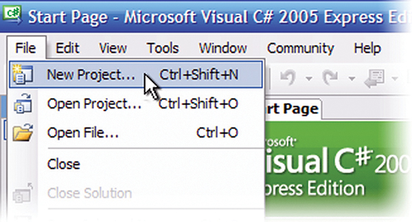 |
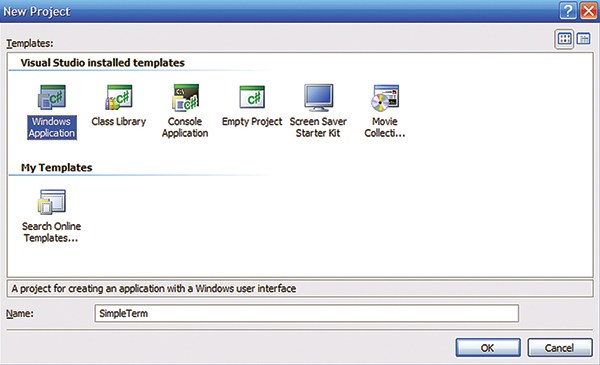
| FIGURE 4. New Project. |
- From the ‘File’ menu select ‘New Project’ (Figure 4).
 |
|
| FIGURE 5. Select Windows Application. |
|
- In the ‘New Project’ form, highlight Windows Application and change the name to Simple Terminal and click the ‘OK’ button (Figure 5).
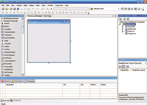 |
| FIGURE 6. AVRStudio IDE. |
|
|
- The IDE should look like Figure 6.
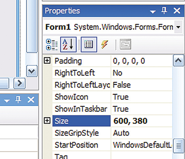 |
| FIGURE 7. Properties. |
- Take note of the various panels. We will call the central panel the ‘Editor Window,’ the left panel the ‘Toolbox;’ the upper right panel the ‘Solutions Explorer;’ and the lower right panel the ‘Properties Window.’ In the Properties Window, change the size from 300,300 to 600,380 (Figure 7).
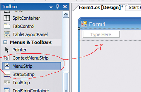 |
| FIGURE 8. Add MenuStrip. |
- In the Toolbox, click and hold the MenuStrip, then drag and drop it on Form1 (Figure 8).
 |
| FIGURE 9. menuStrip1. |
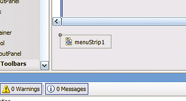
- Note that the specific instance of menuStrip1 of the class MenuStrip appears below Form1 in the Edit Window (Figure 9).
 |
| FIGURE 10. Add RichTextBox. |
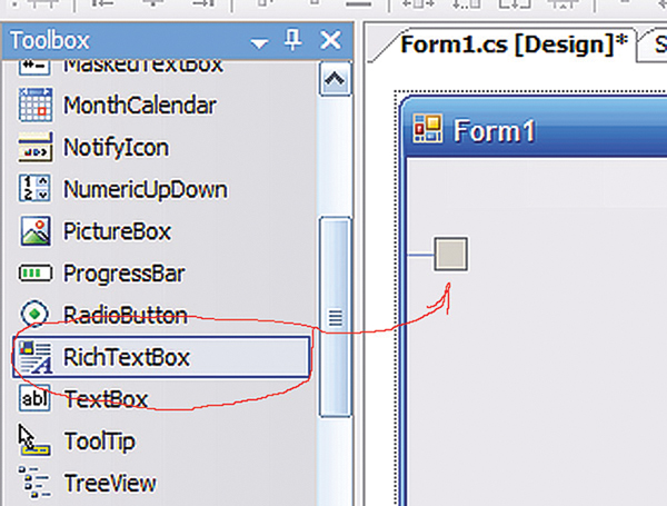
- In the Toolbox, click and hold the RichTextBox. Then drag and drop it on Form1 (Figure 10).
- In the Properties Window, change the richTextBox size from 100,96 to 590,136.
- In the Properties Window, change the richTextBox location to 0,44. (You may be wondering where I’m getting these funky dimensions. Well, I just used the cursor to size the items until they looked right — which you can also do — but if you want to get your Simple Terminal to look exactly like mine, you’ll need to hand-input the dimensions.)
- Add another richTextBox (same size) — richTextBox2 — below the first. Change the location to 0,209.
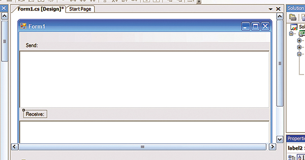
- From the ToolBox, select ‘Label,’ and drag and drop it between the MenuStrip and richTextBox1.
- In the Properties Window, change ‘Text’ from label1 to Send:.
- Select a second label and drop it between richTextBox1 and richTextBox2. Change the Text from label2 to Receive:.
 |
| FIGURE 11. RichTextBoxes. |
- The color scheme is boring! Plain old gray just won’t cut it. Let’s tart this up a bit (Figure 11).
- Select Form1 and in the Properties Window, select BackColor and click the down arrow to show the color menu. Select Bisque.
|
| FIGURE 12. BackColor. |
- In the Edit Window, select the menuStrip1 and in the Properties Window, select ‘BackColor.’ Choose NavahoWhite (Figure 12).
 |
| FIGURE 13. Font. |
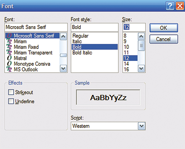
- Select label1 and in the Properties Window, choose Font. Change the Font Style to Bold and the Size to 12 (Figure 13).
- In the Properties Window for label1, select ForeColor and change to DarkGoldenrod.
- Select Form1 and in the Properties Window, change text to ‘Smiley Micros — Simple Terminal’ or some other less commercial name if you prefer.
- While still in the Form1 Properties Window, select Icon and then select ‘Smiley.ico’ (located in the \Software\Graphics\ directory).
 |
| FIGURE 14. GUI with makeup. |
- You’ve got to admit, a little makeup helps (Figure 14).
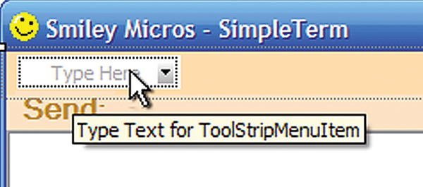 |
| FIGURE 15. Add menu item. |
- Select the MenuStrip and highlight the ‘Type Here’ box (Figure 15).
- Type Settings.
- Move your cursor to the next menu position to the right; type Open Port.
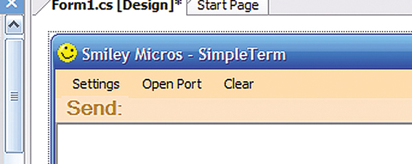 |
| FIGURE 16. Menu items. |
- In the next right, type Clear (Figure 16).
- Now, SAVE YOUR WORK! — Do this every time you have done enough work that you’d feel bad if you lost it. If you didn’t already know this, you will learn it the hard way like the rest of us.
 |
| FIGURE 17. Start debugging. |
- In the Express IDE menus, select Debug and click Start Debugging (Figure 17).
Whoa, look at that! You didn’t write a word of software and yet you just created a GUI for a serial terminal! Click the little X in the upper right to close the debug form.
Making the Simple Terminal GUI Do Something
Add Functionality to the Menu Items
This is what we see in the C# Edit Window:
using System;<br />
using System.Collections.Generic;<br />
using System.ComponentModel;<br />
using System.Data;<br />
using System.Drawing;<br />
using System.Text;<br />
using System.Windows.Forms;
namespace WindowsApplication2<br />
{<br />
    public partial class Form1 : Form<br />
    {<br />
        public Form1()<br />
        {<br />
            InitializeComponent();<br />
        }<br />
    }<br />
}
- In the IDE, double click on the menuStrip1 Settings button.
- In the Edit Window, click the ‘Form1.cs [Design] tab to view the Design Editor panel. Now click the ‘Open Port’ menu item.
- Repeat for the ‘Clear’ menu item.
- In the Form1.cs code window, you’ll see that the IDE has created three functions that will be run when you click the menu item.
- In C#, add the following text to each:
        private void settingsToolStripMenuItem_Click(object sender, EventArgs e)<br />
        {<br />
            MessageBox.Show(“Menu item ‘Settings’”);<br />
        }
        private void openPortToolStripMenuItem_Click(object sender, EventArgs e)<br />
        {<br />
            MessageBox.Show(“Menu item ‘Open Port’”);<br />
        }
        private void clearToolStripMenuItem_Click(object sender, EventArgs e)<br />
        {<br />
            MessageBox.Show(“Menu item ‘Clear’”);<br />
        }
- Run the program in debug mode again (Debug/Start Debugging).
|
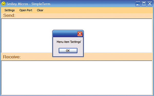
| FIGURE 18. Click the Settings menu item. |
- Click the ‘Settings’ menu item. (Figure 18)
- Likewise, test the ‘Open Port’ and ‘Clear’ menu items.
- Close the debug form.
- Select Form1.cs and change the Clear menu function to:
private void clearToolStripMenuItem_Click(object sender, EventArgs e)<br />
        {<br />
            richTextBox1.Text = “”;<br />
            richTextBox2.Text = “”;<br />
        }
- This will cause the text in the rich text boxes to be cleared.
- Run the program in Debug mode and type some text in each richTextBox. Then click the Clear menu item to see it work.
- The source code is in the \Software\Chapter 4 - Simple Terminal GUI \ directory.
Wrap-Up
In this workshop, we went through the Microsoft tutorials and learned just enough to be dangerous. We also built the GUI for a Simple Terminal. In the next workshop, we will build a dialog form (Settings) to get data from the user for selecting a serial port, and set up the UART. We will then learn to use the Serial Port Class, and finally we will build an Arduino voltmeter that displays the output on a PC. NV
You can find the source code and supplements for this article in Workshop18.zip in the downloads section of the Nuts & Volts website and Smiley Micros website.
The Arduino Projects Kit
The Arduino projects kit is a special hardware pack that will help you get hands on experience as you follow along with this series. It provides components for use with Workshops 9, 10, 11, and many future Workshops. Over time, we'll learn simple ways to use these components, and more importantly, use them to drill down into the deeper concepts of C programming, AVR microcontroller architecture, and embedded systems principles.
The Arduino Projects kit is offered through the Nuts & Volts webstore and Smiley Micros website.
Back to top