With the state of the world today – diminishing oil supplies, global warming, acid rain, and so forth - it’s no surprise that everyone is going green. With high gas prices and the current economic climate, people are looking for ways to do more with less, leaving as little impact on the environment as possible.
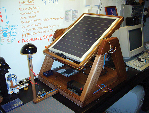
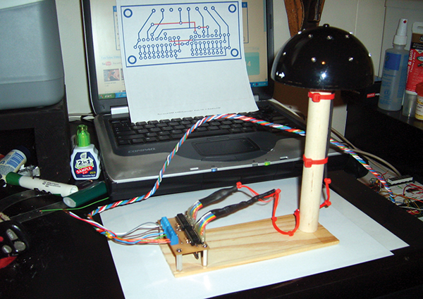
FIGURE 1. Solar Tracker on my robotics shop (i.e., basement) workbench.
Phrases such as “going green” and “carbon footprint” have become ubiquitous and even trendy. The United States Green Building Counsel (USGBC) has even developed a green building rating system called LEED by which new buildings are designed to be as energy efficient as possible. Those with the knowledge to innovate technologies for renewable resources might soon find themselves highly sought after!
WEST VIRGINIA UNIVERSITY INSTITUTE OF TECHNOLOGY
I graduated with my degree in Electrical Engineering from WVUIT in May 2008. As a senior, one of my requirements for graduation was completing a two-semester Senior Design course in which I would be teamed up with two other students to design and construct a mechanism which should encapsulate everything we learned during our time at “Tech.” My goal was to design a green machine which interacts with its environment, comprised of three basic components: devices for input, processing, and output. I, therefore, started with the assumption that I would need someone good at designing electronic circuitry, someone good at computer programming, and someone with a strong mechanical skill set. Though only a novice, I decided that I would tackle the electronics.
On the first day of class, I quickly assessed my five classmates: four electrical engineering students and one computer engineering student. I immediately approached Adam Vincent, the “CompE” major, and asked if he would join my team. He agreed, and I had my software guy. Of the remaining four, I really only knew one of them, Mike Browning, who is a good friend. Mike was older, had worked in industry for years, and possessed a wealth of practical experience. I had my mechanical guy. Together, we three made quite the well-rounded team. We were ready to get to work!
BRAINSTORMING FOR IDEAS
If you caught an episode of the short-run Discovery Channel program Prototype This, you pretty much have the gist of a Senior Design project — only with two semesters instead of two weeks in which to complete it. We were given a budget of only $200 per semester and had to impose our own requirements and constraints on the project. What should we create?
I wanted to design a complete embedded system with custom electronic circuitry. Adam needed something with a fair amount of computer programming to meet his objectives as a computer engineering major. Mike wanted to do something with renewable resources, which narrowed our options considerably. We had available to us a solar panel donated to the department by a recently retired professor, so we decided to go with solar power.
Once a week, we met with Dr. Stephen Goodman, Ph.D., Senior Design instructor and Chair of WVU Tech’s Electrical Engineering department. For the first few weeks, we did nothing but brainstorm for ideas. Our first proposal was a solar power supply for laptops to be used during camping/beach trips. Unfortunately, it was determined that the size and weight of such a contraption would be impractical, and our solar panel simply couldn’t produce the wattage necessary to power a laptop. After several other scrapped ideas, we settled on the wackiest one of all: a solar-tracking power supply for a mobile unit (Figure 1); a device that not only provides power to sustain its own functions (tracking the sun for optimal energy collection), but also for propulsion and steering of an unmanned vehicle. Fortunately, we didn’t have to design the mobile unit. We only had to design the solar tracker, with the provision that it have enough energy left over (stored in a battery) so that it could power a mobile unit.
DECISIONS, DECISIONS
It was the intent of this course to give us a taste of real-world engineering; as such, all decisions were based upon things such as safety, cost, manufacturability, power consumption, component strengths/weaknesses, and impact on the environment. In order to quantify these multiple factors, engineers use a tool called a decision matrix — nothing more than a chart which uses weighted values to compare the merits of different candidate solutions to a problem. All of the weighted values are tallied, and the candidate with the highest total wins.
For example, we had to select an actuator to position the solar panel so that maximum surface area faced the sun. What kind of actuators should we use: stepper motors, servos, or regular DC motors? I was biased toward steppers because I’m a big nerd and had already spent a lot of my own spare time (more than I care to admit) designing a stepper motor driver and really wanted to implement it. But were stepper motors really the best solution for this project? Having never used servos before, we researched them extensively.
Many tests were run on all three candidates. Our solar panel only produced 20 watts of energy, so actuator power consumption was heavily weighted. Torque and accurate positioning were also paramount. As it turned out — much to my dismay — servos were determined to be the best candidate solution. They are internally geared down, providing adequate torque to move the solar panel. Servos also have internal circuitry which provides negative feedback for accurate positioning — saving us from having to design an external feedback device (such as an optical encoder). They also consume less power than stepper motors. So, though I didn’t get to use my custom stepper motor driver, I did learn a lot about servos.
FIGURE 2. A labyrinth toy.
Decision matrixes were also used to determine the best mechanism for positioning the solar panel. We considered moving a big lens to focus the sun’s rays on the panel. This method would have focused a lot of sunlight (solar energy) on a small fraction of the solar panel’s surface, but would the increased local power density be worth the unused real estate? We also considered pivoting the panel on the end of a rod, which came to be termed the “joystick” method. We finally settled on using a frame-in-a-frame method, like the old labyrinth toy (Figure 2). This provided two axes of motion and the simplest mechanical design.
After months of decision matrixes, Gantt charts, and lots of other boring stuff, we were finally ready for the fun part — prototyping!
THE “BUG EYE”
Okay, remember the three basic elements of a good, interactive machine that I mentioned earlier: input, processing, and output? Think about it like this. Say you want to pick up an apple. First, you look around (input). Light is reflected off of everything around you and into your eyes. Your retinas receive the light and send electrical impulses to your brain, which interprets those signals allowing you to locate the apple (processing). Your brain then sends electrical impulses to your muscles, directing your hand to pick up the apple (output).
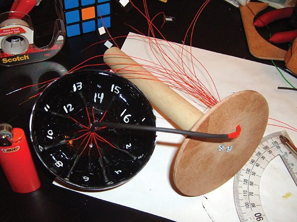
FIGURE 3. Inside the BugEye with its “optical nerve” wires.
We started by designing an input device. How do you make a machine look for the sun? Why not build an analog eye (Figure 3)? We constructed a four inch diameter semi-spherical plastic dome with an array of 16 phototransistors evenly spaced about its surface (Figure 4). It appeared to be a multi-faceted bug eye, so that’s what we called it! Each of the 16 phototransistors was placed in series with a 330 ohm resistor between +5 volts and ground, creating 16 voltage divider circuits.
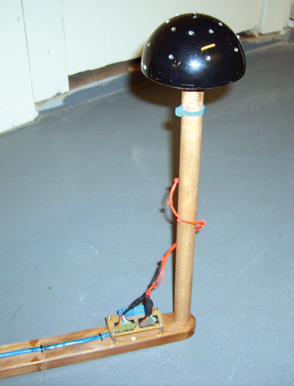
FIGURE 4. The completed BugEye and Analog-to-Digital Converter (ADC) circuit.
A voltage divider works using two parts: a fixed resistance (330 ohms) and a variable resistance (phototransistor). As any one phototransistor is exposed to light, a tiny current is produced at its base which causes an even greater current to flow from its collector to emitter. The more light focused directly at the phototransistor, the more collector current will flow. As the collector current increases, so does the voltage drop across the fixed 330 ohm resistor.
There is only a total of +5 volts to be split between the resistor and phototransistor; so as more voltage drops across the fixed resistor, the greater the voltage drop ratio of resistor to phototransistor. This provides an analog measure of the amount of light that any one phototransistor sees. The area of the bug eye experiencing the greatest fixed-resistor voltage drops is the area hit most directly by the sun. That is how a machine looks for the sun!
COVERING NEW GROUND
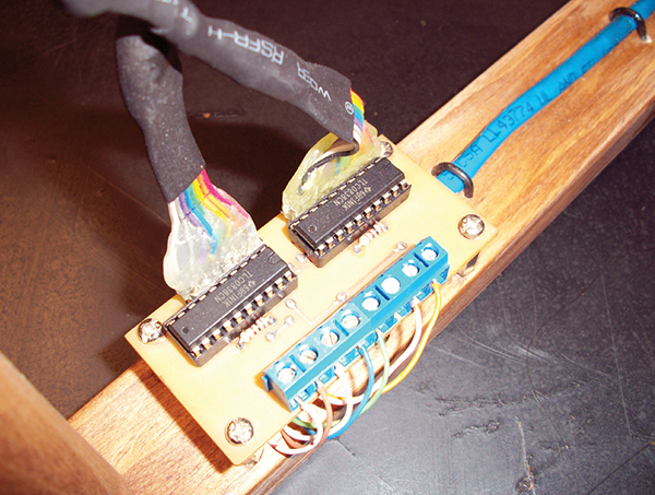
FIGURE 5. Two TLC0838CN 8-bit, 8 channel ADC chips on a homemade printed circuit board.
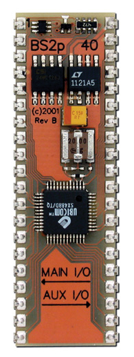
FIGURE 6. A Parallax Basic Stamp II with 40 pins (BS2p40).
Uh-oh! Problem: The bug eye was speaking one language (analog), but the microprocessor only spoke digital! What we needed was a translator between them — an analog-to-digital converter (ADC) (Figure 5). This also posed another problem: serial communication — the way that the ADC and microprocessor talk to each other (something I knew nothing about!). Adam, wishing to avoid learning a new microprocessor and programming language, chose to go with the Parallax BASIC Stamp II (BS2p40) (Figure 6). He had used it before and was familiar with it. I, on the other hand, had never used a BASIC Stamp; as the electronics buff of this group, I would have to do a bit of programming while prototyping the circuitry. So, there I was trying to make an “eye” and a “brain” communicate, and I knew nothing about analog-to-digital converters, BASIC Stamps, or serial communication. Talk about a learning curve!
First, I played around with the BS2p40, quickly and easily learning how to program it (a heartfelt thank you to Parallax for such good documentation!). Then, I studied the eight-bit ADC’s datasheets at length, specifically the timing diagram. Once I understood what all of the pins were for and exactly when to set/clear certain bits, I was ready to tackle serial communication.
I wrote a few simple programs, bit-banging (sending one bit at a time) serially between the ADC and BS2p40. With a little troubleshooting, I realized that serial communication isn’t really that complicated. It’s nothing more than sending a stream of 0s and 1s one after another. The only tricky part is getting the timing issues right and the setup, start, and stop bits. I also discovered the SERIN (SERial IN) and SEROUT (SERial OUT) serial communication commands make the code much simpler (rather than bit-banging). It worked beautifully (Figure 7)!
FIGURE 7. Prototype of BugEye and ADC circuit.
Depending upon how much light hit a phototransistor, a certain analog voltage would be measured on one of the 16 channels of the two ADCs. A binary (or digital) representation of that analog voltage would then be sent serially from the ADC to the BS2p40. The Stamp polled each of the 16 channels sequentially, stored their values, and then compared them to find the three greatest binary numbers ranging from 0 to 255. Why 0 to 255? Eight bits imply a resolution of 2^8 or 256 values. The three phototransistors with the largest voltage drops (and corresponding binary numbers) must therefore be the three pointed most directly toward the sun. And with that data, we knew the location of the light source.
POSITIONING METHODS
By this point, we had taken care of all the input and a third of the processing. Now we needed to interpret the data from the sensors and figure out how to make the servos position the solar panel facing the sun. So, how do you map a semi-spherical 16-point array onto a two-axis pan and tilt mechanism? We had to tell each of the servos exactly where to turn, so the resulting normal vector pointed in the direction of the sun.
Adam started out with a really complicated neural networking scheme which would have given us amazing results. But due to the complexity of the neural network and project time constraints, Adam decided to water it down to the “triangle” method. In this method, he would program the BS2p40 to identify the brightest three phototransistors and calculate a weighted average based on their values. That would give him a point somewhere inside the triangle as a target for the panel. Unfortunately, graduation day was fast approaching, and time was running short. At the last minute, he ditched that method, as well. He finally calculated the servo positions (and their corresponding frequencies) for the midpoints of each triangle. This wasn’t as flexible as neural networking or weighted averaging, but it did the job.
NO REST FOR THE NERDY
FIGURE 8. Solar Tracker coming together in the WVU Tech machine shop.
During that last semester at WVU Tech, I probably got an average of two hours of sleep per night. I spent nearly every night (until the break of dawn) in the machine shop (Figure 8). Whenever my mind was free to wander throughout the day, I thought about this project. I rolled ideas round and round in my head, contemplating my designs from every conceivable angle. I was looking for flaws and trying to figure out the order of construction. Anyone who has ever designed a complicated machine knows that the order of construction must be strategically planned — lest you make a permanent, irreversible move only to realize that you should have done something else first. It’s agonizing, yet euphoric at the same time! It is creation, and it is wonderful; there is no better feeling!
THE MOMENT OF TRUTH
The three of us stayed up the entire night before the big presentation. An erroneous line of PBasic code pushed one of our servos beyond its mechanical limits, stripping the gears inside. Mike and I had to drive an hour away to pick up a replacement servo while Adam furiously rushed to complete the computer code. When we finally finished the solar tracker — just an hour before the presentation — we were exhausted! After showers and a quick change of clothes, we made a mad dash for the engineering building.
There we stood in front of a classroom full of professors and fellow students, waiting to be judged. It was the moment of truth, the culmination of seven months of hard work — and supposedly the crowning achievement of our college educations. We each took turns telling about the different aspects of the project, all the while wondering if it would work at the crucial moment. Then, with mounting tension and nervous trepidation, I flicked on the power switch! For a moment, there was nothing but silence as the entire room looked on in wide-eyed anticipation. Then suddenly, as all the air in the room seemed to be sucked up in one collective gasp, it jerked to life and smoothly positioned itself toward the light source (an incandescent flood lamp). It worked!!! I think that Adam, Mike, and I were just as shocked as everyone else.
We received many questions and compliments. Though bulky, heavy, and not nearly as efficient as it could have been, it worked! We each received an A in the course. When Dr. Goodman told me that this solar tracker was the quintessential Senior Design project, I felt that all of our hard work had paid off.
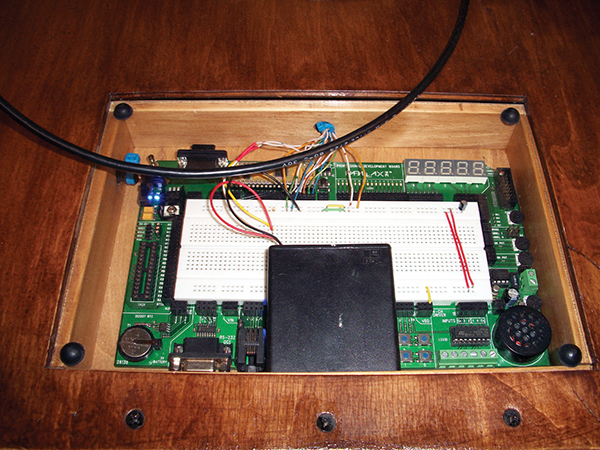
FIGURE 9. Glass cover plate over recessed BS2p40 microcontroller board.
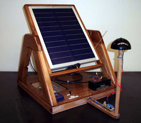
Six months after graduation, I borrowed the solar tracker from WVU Tech’s Electrical Engineering department and made several modifications. I recessed the microprocessor inside the base with a glass cover plate to protect it from dust (Figure 9). I added a power connector and voltage regulator, so that the tracker could be powered from a wall wart (for repeated indoor demonstrations and resulting lack of solar charging). I made the bug eye’s arm retractable for ease of transit and storage. And finally, I sanded, stained, and polyurethaned the solar tracker for a high gloss shine. If this device was going to be my legacy at WVU Tech, I wanted it not only to work but also look nice (Figure 10)!
FIGURE 10. Finished Solar Tracker after some modifications in January 2009.
FINAL THOUGHTS
I have come a long way in my pursuit of robotic/electronic knowledge, and I realize that I have merely scratched the surface. For every success that I enjoy, there have been many hundreds of miserable failures. If you are new to electronics and have an intense desire to learn, then DO NOT GIVE UP — EVER!!! After years of midnight tinkering and scores of mind-numbing boring books, I am finally starting to get this stuff. New and wonderful possibilities are presenting themselves to me, and it is an amazing feeling!
If you are interested in building a solar tracker of your own, see the downloads section at the end of this article at [url=http://www.nutsvolts.com]http://www.nutsvolts.com[/url] for block diagrams, wiring diagrams, schematics, datasheets, parts lists, and code. NV
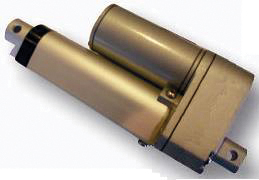
Linear Actuators
In the process of writing this article, I was asked why we didn’t use linear actuators. To tell the truth, we hadn’t even considered it. A rotary actuator with spur and pinion gears requires constant power to hold a fixed position, whereas a linear actuator with a screw or worm gear can hold its position without being energized — thereby consuming less power. Linear actuators might have been a good solution!
West Virginia University Institute of Technology www.wvutech.edu
Binary Numbers
The numbers that we use every day (0 - 9 or some combination thereof) are part of the decimal number system. Computers use the binary number system (0 and 1) because their transistor logic gates have two states: off and on. Computers represent decimal numbers as a string of zeros and ones.
Say, for example, that one of the Bug Eye’s light sensor voltage divider circuits is measuring 2.7 volts. The microprocessor (BS2p40) doesn’t understand 2s and 7s, only 0s and 1s. So, the analog voltage (2.7V) has to be converted to a binary (or digital) representation for the computer to understand.
Here’s how to make the conversion yourself: That’s 2.7 volts out of a maximum five volt reference; 2.7 divided by 5 equals 0.54 or 54%. Since we used eight-bit analog-to-digital converters, that means that the resolution of the binary value is 2^8 or 2x2x2x2x2x2x2x2 or 256 (values 0 - 255). Now, 54% of 256 is 138, but we say 137 since we’re starting at 0 instead of 1.
So, now we have a prorated value of 137 out of 256 (the same ratio as 2.7 out of 5). Next, we represent the decimal number 137 in binary form; 137 in decimal equals 10001001 in binary. Notice the decending powers of two below.
Therefore, the microprocessor now understands 10001001 to mean 2.7 volts (or a little more than half of the five volt reference) is being measured by that particular light sensor. After polling the other 15 light sensor circuits, the computer can compare the binary representations of those voltages and decide which three are seeing the most light — and therefore determine in which direction the sun is located.
West Virginia University Institute of Technology
If you are interested in studying engineering, I personally recommend WVU Tech! In 2007, WVU Tech was named as one of the nation’s top 100 Undergraduate Engineering Programs by US News and World Report. With an enrollment of only 1,452, the faculty/student ratio is very low — which means a lot of individual attention.


 Linear Actuators