What's a watchdog timer? Many of you who have worked with single board computers are familiar with watchdog timer circuits. These circuits monitor the operation of the microcontroller and its software and restart it if a problem is detected. Watchdog timers are an excellent way to insure that a microcontroller-based system continues to operate unattended if occasional failures occur.
There are a number of reasons why your microcontroller might need this kind of monitoring: operation in a harsh environment that creates electrical "spikes," hardware conditions that the software could not be tested for, and — yes — even "bugs" in the software.
The way that a watchdog timer does its job is to monitor a particular signal sent by the microcontroller. If this signal does not occur on a regular basis, it assumes the microcontroller is "locked up" or the software is "lost" and cannot send this signal. It then restarts the system.
What We Needed
I was talking to one of our customers recently about our RC51 Programmable Relay Controller, which is based on an Atmel AT89C4051 microcontroller chip. He asked about the reliability of microcontroller-based systems in harsh environments. Although our full-featured, single board computer has a built-in watchdog timer chip, our single microcontroller chip-based products — like the RC51 — do not.
Even though we have found that the RC51 and other products based on single microcontroller chips are very resistant to the problems associated with harsh environments, I realized that it would be nice to increase its reliability further — if the need arose — with a simple standalone watchdog timer circuit.
What I Designed
Watchdog timer circuits can either be included in the circuitry on a single board computer or microcontroller or they can be standalone devices connected to a variety of signals. If the circuit is included on a single board computer, it usually restarts the software by issuing a hardware reset to the microcontroller, just as though someone had pressed a reset button.
What if your microcontroller does not already have a watchdog circuit? Any add-on circuit would need to interface to the reset circuitry on the board. This may not be a practical thing to do, but, if the watchdog timer is a standalone circuit with a relay, it can cycle the power so that the microcontroller will reset itself when powered up.
Since all of our controllers (and most single board computers) have a source of 5 volts to power small external circuits, in addition to an available spare logic level output, I was set. I decided to design a simple circuit that is easy to connect to nearly any small, single board computer or microcontroller circuit that can restart these devices by power cycling them.
Circuit Description
The circuit shown in Figure 1 is based on a common CMOS chip — the MC14538 — or equivalent dual edge triggerable, retriggerable, and resettable monostable multivibrator (timer).
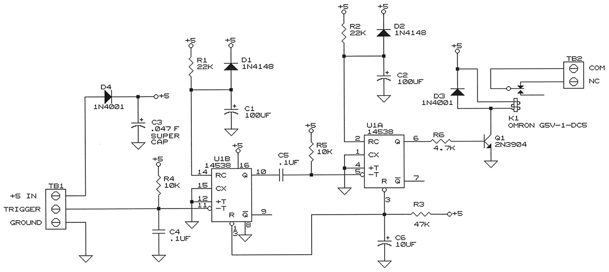
FIGURE 1. Schematic of the watchdog circuit. Note that C3 is in Farads, not µF.
Its ability to lengthen its output pulse when retriggered is the basis for the operation of this circuit. Although the 14538 is versatile enough to have both rising and falling edge trigger inputs, only the falling edge triggers are used.
The first timer section is used to monitor a low going logic level or current sink trigger pulse, which the microcontroller being monitored must continue to pulse at a certain interval. The second timer section is used to activate the relay for a specified amount of time once the first timer determines that the trigger pulse has stopped. (With the values listed in the Parts List, both of these time periods are set to approximately 2.2 seconds.)
Parts List
| ITEM |
DESCRIPTION |
| U1 |
MC14538 |
| K1 |
Omron G5V-1-DC5 (see text) |
| C1, C2 |
100 µF electrolytic |
| C3 |
.047 Farad, 5.5 V "SuperCap" |
| C4, C5 |
0.1 µF |
| C6 |
10 µF electrolytic |
| D1, D2 |
1N4148 or 1N914 |
| D3, D4 |
1N4001 |
| Q1 |
2N3904 or 2N2222 |
| R1, R2 |
100K 1/4 W |
| R3 |
47K 1/4 W |
| R4, R4 |
10K 1/4 W |
| R6 |
4.7K 1/4 W |
| TB1 |
3 pin terminal block |
| TB2 |
2 pin terminal block |
| ALTERNATE PARTS |
| D4 |
1N5819 Schottkey diode |
| U1 |
74HC4538N |
When you are ready to begin using the watchdog timer circuit, all you need to do is have the microcontroller begin sending low going pulses to it at least once every second or so. From that point on, the microcontroller must continue to send these pulses or the relay will activate and restart the microprocessor. The values shown in the schematic and Parts List provide a time of about 2 seconds for each timer section and can be changed, as described in the next section.
The relay was chosen for its small size and fairly low coil current consumption — about 30 mA at 5 volts. Its contacts can handle 1 amp at 24 volts — more than enough to cycle the power of many microcontroller circuits and boards. Another component that deserves mention is the .047 farad, 5.5 V "SuperCap" used for C3. This capacitor is a Panasonic EEC-F5R5U473 or equivalent and was chosen over electrolytic capacitors because of its large capacitance for its size.
How it Works
D4 isolates the 5 volt power going to the watchdog circuit. If the watchdog timer removes power from the microcontroller circuit (which is providing the watchdog with power), the charge in C3 will be blocked and will not try to go back and power the microcontroller.
Since the circuit uses such a small amount of current, the voltage drop across D4 is quite small. The measured voltage with most 1N4001 series diodes is 4.7 volts or more when C3 is fully charged. This voltage meets the requirements for CMOS chips (3 to 18 volts) and is more than enough to operate the relay, which has a coil voltage rating of 5 volts and a pull-in voltage of 80% of its rated voltage.
C6 and R3 form a power-up reset to the chip's reset pins on both sections to insure that the outputs are in the reset state ("Q" outputs low) after the power stabilizes upon power-up. D1 and D2 are recommended by the chip's data sheet to avoid large discharge currents through the chip when large value capacitors are used for long timing delays.
R4 provides a pullup for the trigger input of the first timer so that an open collector signal, as well as a logic level signal, can be used to pull it low and provide the falling edge to trigger it. C4 is a filter and provides a small degree of protection from static and false triggering.
When a low going trigger pulse is sent from the microcontroller, the first timer will start and will set its Q output high. Q will remain high as long as another pulse occurs before the timing period ends; otherwise, it will return low. C1 and R1 control the time period of the first timer. R5 holds the falling edge trigger of the second timer high until C5 pulls it low through the Q output of the first timer. This arrangement creates a falling edge before the capacitor charges and allows only a high to low transition of the Q output to trigger the second timer that controls the relay.
When the second timer is triggered, its Q output turns on the relay via R6 and Q1 by sinking the relay current to ground. C2 and R2 control the time period of the second timer, which is the relay "on time."
When the relay activates, its normally closed contact that supplies power to the microcontroller being monitored opens and removes the power. This, of course, removes power from the watchdog circuit, but C3 has sufficient charge to operate the relay for a short period of time. When the relay deactivates, power is returned to the microcontroller (which restarts) and to the watchdog timer circuit.
Building the Circuit
For prototypes of simple circuits that can be laid out on single-sided printed circuit boards (PCBs), I prefer to etch my own handmade boards. Circuit layout is done with PCB layout software and then printed at a one-to-one scale to use as a guide to drilling the holes. A larger version is then printed in reverse to be used to create the layout with dry transfer patterns and a resist pen. (Actually, I often use diluted fingernail polish and a paintbrush with only 10 hairs remaining to paint on the circuit paths.) Figure 2 shows a picture of the completed board connected to our RC51 Programmable Relay Controller.
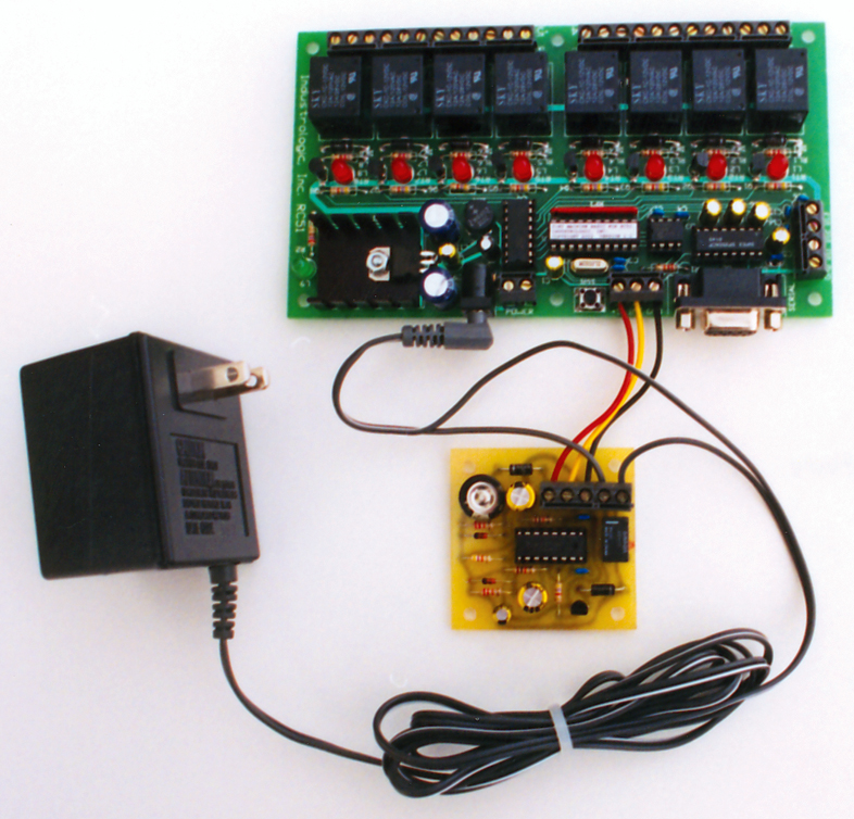
FIGURE 2. The circuit (bottom) guarding a controller.
Using the Watchdog Timer
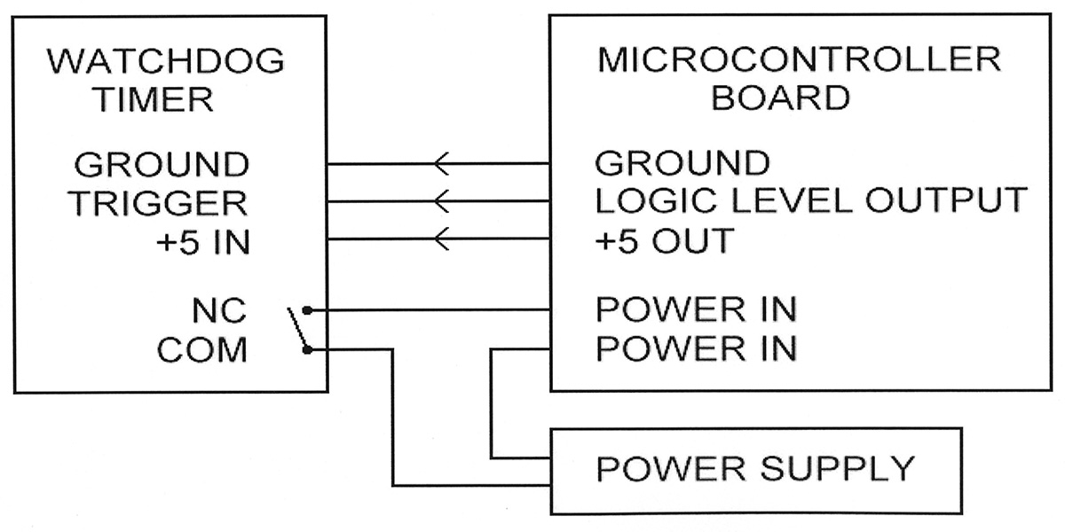
Figure 3 is a block diagram of how the watchdog timer is connected to the RC51 and other microcontroller boards.
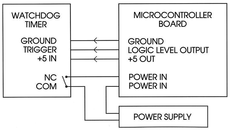
FIGURE 3. The system wiring diagram.
The digital output signal used during testing with the RC51 was the general-purpose digital I/O signal called “INT.” The RC51 has a simple onboard language called Tiny Machine Basic, so it was easy to write a test program that shows how to trigger the watchdog timer. The program below allows the RC51 to be used as an “RS-232 relay” board where a host computer can operate relays based on the binary value of a character sent to the RC51.
1 INT=0 set the digital output low (trigger watchdog)
2 INT=1 set the digital output back high
3 A=KEY get the character at the serial port
4 IF A=0 1 if there is no character, keep looping
5 RELAYS=A set relays to binary value of character
6 GOTO 1 keep looping
Modifications to the Circuit
C1 and R1 control the period of the first timer. This time determines how long the circuit will wait for a pulse from the microcontroller before determining that there is a problem. C2 and R2 control the relay "on time" and can be changed. (Remember, however, that C3 may not have enough charge to provide power to the circuit for long periods of time.) The time delays for both timer sections are calculated like a simple R/C time constant, that is, capacitance in farads (microfarads divided by 1,000,000) times resistance in Ω. As stated, a Schottky diode like the 1N5819 can be used for D4 instead of the 1N4001. This diode has a lower voltage drop and the measured voltage of the circuit will be very close to 5 volts. This will be helpful if other relays are selected that use more current.
A 74HC4538 high speed CMOS chip can also be used instead of the CMOS 14538, in which case the Schottky diode may be desired, since the HC part uses slightly more current. If your single board computer has a reset switch that terminates at a connector, you may want the watchdog timer to restart your microcontroller with a reset. In that case, you can use the normally open contact on the relay instead of the normally closed contact, so that the relay acts like a reset switch. You may also want to shorten the time delay on the second timer section by using a lower value for R1.
The watchdog timer circuit can, of course, be powered by its own 5 volt power supply. This will allow the second timer to complete its entire timing cycle set by the timing components R2 and C2, rather than ending prematurely when the power is removed. This modification may be required if there is a specific power off time needed to restart the system. NV