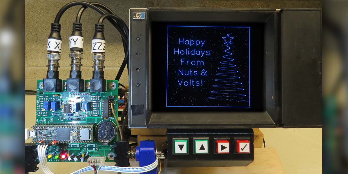
Using the TEENSY 3.6 CPU to Make a CRT Clock!
The February and March 2018 editions of Nuts & Volts featured my article detailing the Arduino Graphics Interface (AGI) project which described a general-purpose hardware and software platform that could draw graphical objects onto the face of any analog oscilloscope.
Nuts & Volts reader and Stanford Engineering Professor, Greg Kovacs contacted me and took exception to the cost and age of the Arduino Due used in that article. He challenged me to see if the AGI concept and software library could be ported to the newer and faster TEENSY 3.6 processor. This article describes the new and improved TEENSY Graphics Interface project that implements a fully operational “CRT clock” as a working demonstration of a TEENSY based graphics platform.
Before the advent of LCD screens for computers and televisions, we lived on a steady diet of cathode ray tubes (CRT) for viewing video and computer graphics images. While CRT televisions form pictures by raster scanning the screen, the earliest computer graphics displays simply “painted data,” point by point, driving an electron beam in a simple XY fashion all about the face of a phosphor coated screen. Wherever the beam was positioned, a dot of light would be seen. Such display systems were basically up-sized oscilloscopes that enabled computers to plot drawings and graphics for scientific, engineering, architectural, and other early line-draw applications. This project shows how a $30 Arduino TEENSY computer board plus a simple and low cost interface circuit can be connected to a CRT based analog oscilloscope to reproduce the guts and performance of a computer graphics terminal such as the ‘70s era Tektronix 4010 (Figure 1). While TGI has many possible applications, the demonstration code developed here includes a working CRT clock as an example of this “retro-technology” in action.
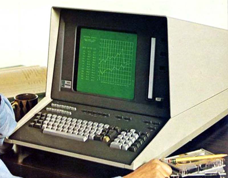
FIGURE 1. Tektronix XY interactive graphics terminal circa 1975.
TGI Overview
The block diagram of the TEENSY Graphics Interface (TGI) is shown in Figure 2. It’s based on the TEENSY 3.6 CPU board, designed and sold by Paul Stoffregen (see www.pjrc.com). This is a fast and powerful computer board that can be easily programmed from within the Arduino Integrated Development Environment (IDE) and readily interfaced to an oscilloscope with just a handful of external parts.
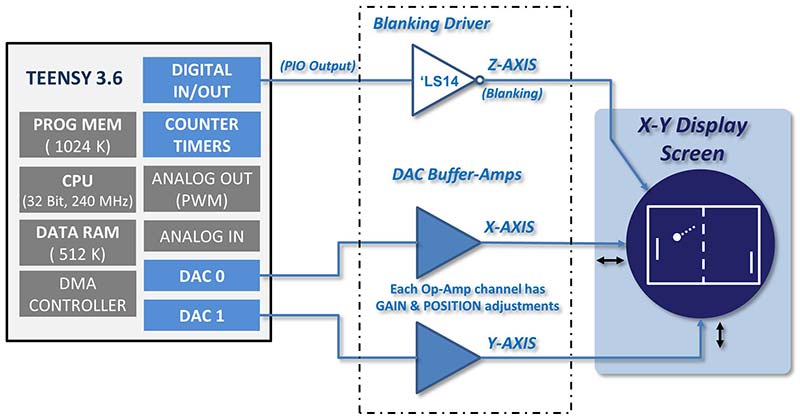
FIGURE 2. TEENSY Arduino Graphics Interface (TGI) block diagram.
In addition to high speed operation, the Cortex 32-bit CPU within the TEENSY also contains a pair of 12-bit digital-to-analog converters (DACs). We use these two DACs to make voltages to drive the electron beam of an analog oscilloscope in X and Y directions. For this project, the internal oscilloscope time base that usually drives the X axis is not used. Instead, all information for deflecting the CRT beam comes directly from the TEENSY DACs and a simple TGI board.
Drawing Objects to the Screen with a TEENSY
Each DAC on board the TEENSY computer is internally connected to the CPU through an unsigned 12-bit-integer data register. When this data register is loaded with the integer 0, the DAC outputs a voltage near zero VDC. When the DAC register is loaded with the integer number 4095, the DAC outputs 1.5 VDC.
For the X axis of a standard oscilloscope, increasing voltages move the electron beam of the CRT from the left to the right side of the screen. Similarly, for the Y axis, increasing voltages will move the electron beam from the bottom to the top of the screen. By connecting one DAC to scope the X axis and the other to scope the Y axis, we can drive the electron beam all about the face of the CRT.
When all is said and done, this creates a graphical coordinate system as depicted in Figure 3. It is seen that when XY=(0,0), the beam is positioned in the lower lefthand corner of the screen. When XY=(4095,4095), the beam is positioned to the upper righthand corner of the screen. The ‘dot’ can be easily moved all about by simply changing the two 12-bit numbers placed into the DAC data registers. You can see that moving a single dot about the screen is easy and straightforward. To construct complex objects such as lines, circles, and text, all we need to do is plot many individual points in a pattern that builds the image we want to show.
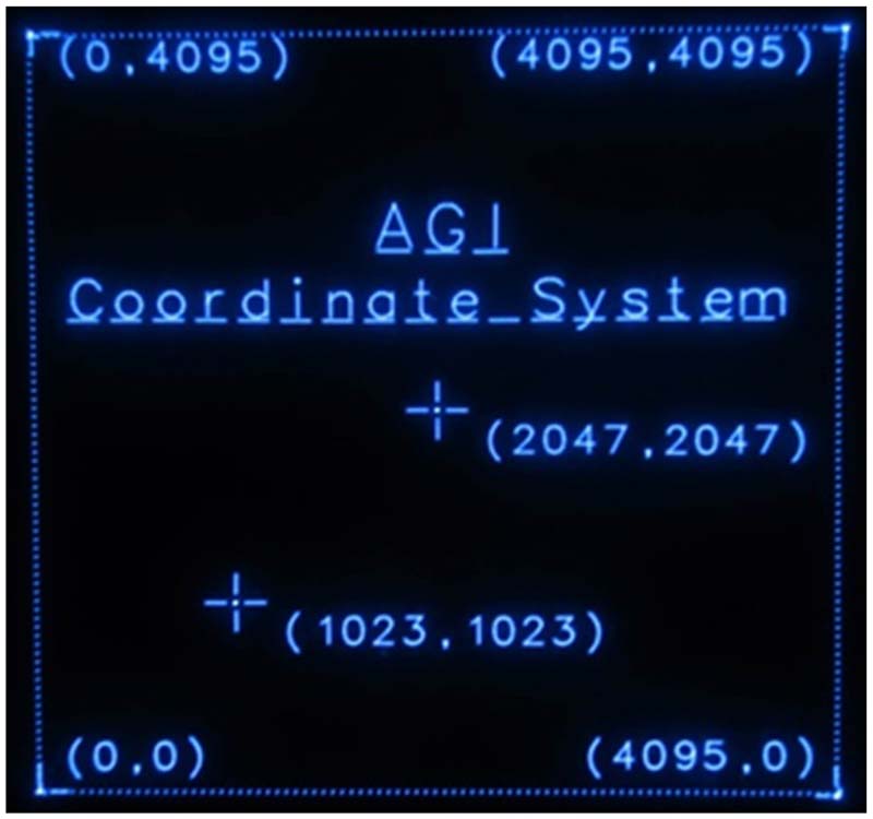
FIGURE 3. The graphics interface coordinate system.
The ‘dotted lines” of Figure 4, for example, show that individual points are discerned whenever the points are spaced far apart from one another. Alternately, when closely spaced, adjacent dots merge together to form solid lines and arcs. So, you might ask, how many points are actually needed for a complex image? The clock face appearing at the top of this article can be rendered with less than 7,000 points. The “bouncing ball” example (Figure 4) contains almost 13,000 points.
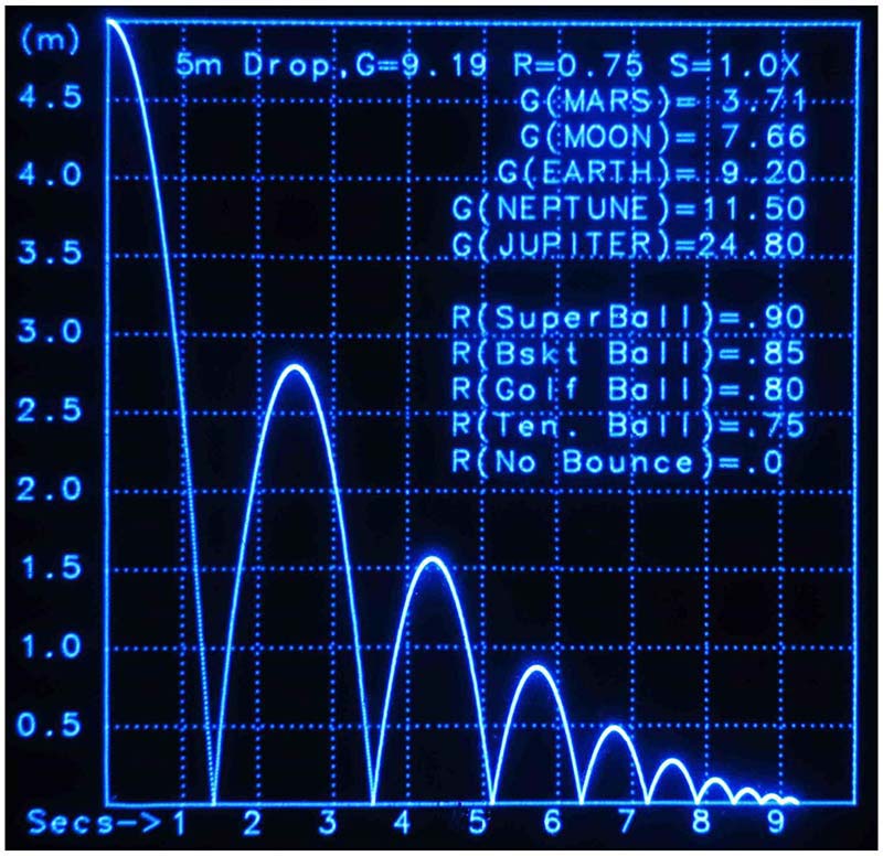
FIGURE 4. A “bouncing ball” example.
Drawing is as Simple as 1-2-3!
Figure 5 shows the steps needed to draw onto the face of your scope.
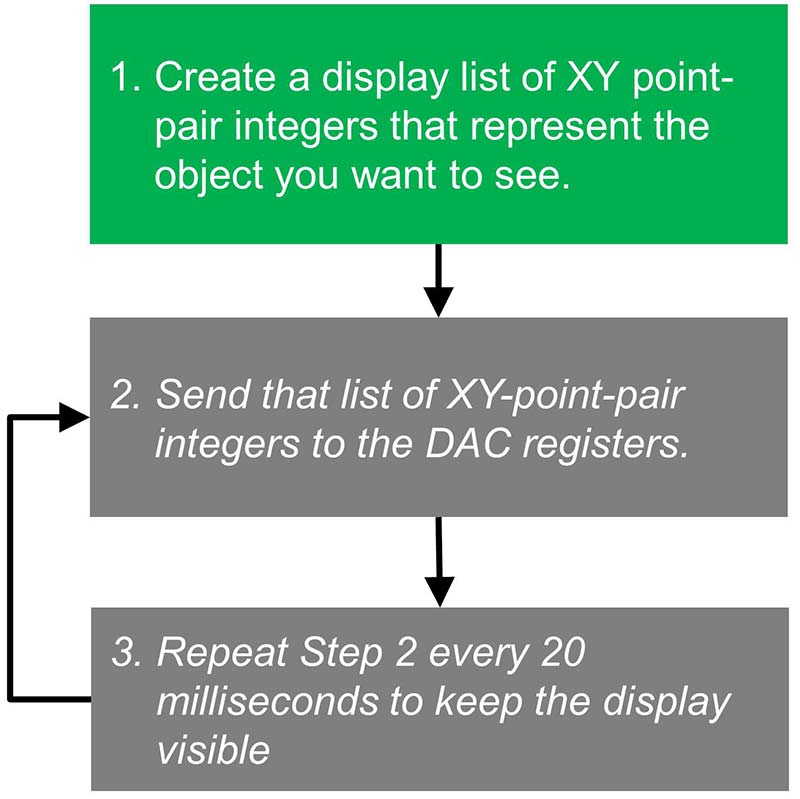
FIGURE 5. Drawing to the scope screen.
First, we must fill the XY_List( ) array with a point pattern of what we want to see. Next, when the point list array is complete, we perform step 2 which is sending the whole point list to the DAC registers. This actually paints the point list onto the scope screen.
As with all CRT displays, the light emitted from a displayed point fades quickly once the beam moves on to a new location. To keep the display visible and flicker-free to the observer, it’s necessary to continuously repaint (a.k.a., refresh) all the points to the screen (step 3) at least 50 times per second.
While at first glance, these three steps may look a bit daunting, the support library, XYscope does all the heavy lifting. In fact, the programmer need only think about step 1. Fortunately, the library contains a full set of drawing subroutines that make this step easy.
Take a look at XYscope.h to see the full list of the available subroutines and their calling parameters. Next, run and then read through the demo code to see working examples of the various routines in action.
“To DMA or Not to DMA, that is the Question …”
The Arduino Due project used Direct Memory Access (DMA) features within the Due to drive the XY_List[ ] out to the DACs. While this minimized CPU refresh loading, this approach required external logic chips and analog sample & hold circuits in order to properly synchronize the X-DAC load, Y-DAC load, and unblank events. This extra complexity added more ICs into the design and made things less straightforward.
While the TEENSY also features a DMA controller, I found I could leverage the higher CPU speed of the TEENSY to simplify both the hardware and software. The TGI design presented here uses simple programmed I/O (PIO) instructions to transfer data from the XY_List[ ] array to the DACs. A single PIO bit is then used to drive the Z axis UNBLANK signal.
With this scheme, synchronizing the two DACs to the UNBLANKING pulse is all accomplished in software rather than hardware. I was happy to find that with the TEENSY, this simplified approach proved to be very fast and worked extremely well!
Although Simple, There’s No “Free Lunch”
By using PIO methods, the TEENSY Graphics Interface circuitry has been reduced to just one dual op-amp and one TTL inverter. However, since the hardware has been simplified, a greater burden is placed on the CPU. In fact, the CPU must programmatically push the entire XY_List[ ] array out to the DACs during every screen refresh cycle. This would kill a lessor processor, but with the TEENSY running full-out at 240 MHz, operations remain fast and responsive. With its speed, more than enough CPU horsepower remains to run the CRT clock app or even much more complex programs.
CPU “Refresh Load,” “Compute Availability,” and other “STATS” are measured and reported at the bottom of the main menu printed to the serial monitor (look ahead to the code listing in Figure 14). For the analytical folks out there seeking even more, I’ve included a Dhrystones (see sidebar) benchmark measurement as one of the demo options. Simply pick a demo TEST PATTERN option to load up the XY_List[ ] array, then select option ‘d’ to measure Dhrystone performance. Try this while varying the number of points in the XY_List[ ] and you’ll get a good sense of how the CPU is impacted by the number of points plotted during the refresh task.
Dhrystone is a synthetic computing benchmark program developed in 1984 by Reinhold P. Weicker intended to be representative of system (integer) programming. The Dhrystone grew to become representative of general processor (CPU) performance. The name “Dhrystone” is a pun on a different benchmark algorithm called Whetstone.
With Dhrystone, Weicker gathered meta-data from a broad range of software, including programs written in FORTRAN, PL/1, SAL, ALGOL 68, and Pascal. He then characterized these programs in terms of various common constructs: procedure calls, pointer indirections, assignments, etc. From this, he wrote the Dhrystone benchmark to correspond to a representative mix.
Dhrystone was published in Ada, with the C version for Unix developed by Rick Richardson (“version 1.1”) greatly contributing to its popularity.
Courtesy of Wikipedia
Hardware Circuit Details – XY Analog Drivers
The schematic for the XY analog drive circuits is shown in Figure 6.
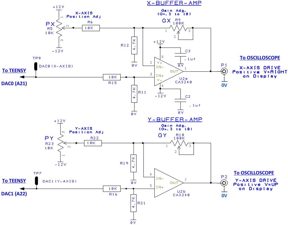
FIGURE 6. Schematic of X and Y buffer op-amps.
Here, an op-amp receives the voltage from each DAC and buffers and amplifies the signal before sending it onto the scope. A single eight-pin CA3240 dual op-amp handles the job for both channels.
About the CA3240 op-amp ... After evaluating several high-speed op-amp devices, I found that the old-faithful CA3240 provided a good combination of speed and stability. Although it’s been around for more than 10 years, the CA3240 is still readily available through Digi-Key and other dealers and distributors.
Hardware Circuit Details – Z Axis Digital Driver
The block diagram of Figure 2 shows a third signal — Z axis blanking — going to the scope. This signal allows us to turn the electron beam on and off in concert with the X-Y beam positioning signals.
In practice, we want to flash each point “ON” only after the beam has moved and is fully settled into position. Similarly, we want to turn the beam “OFF” before moving on to the next position. With this tactic, point-to-point-transition artifacts are hidden, and only the desired end-points are visualized.
Figure 7 shows the detailed schematic for the Z axis driver. Just a couple of inverters are used to provide level conversion (3.3V to 5V) and buffer the TEENSY from the outside world. Although most scopes use POSITIVE UNBLANK LOGIC (logic 1=UNBLANK), both logic options are provided by the TGI ‘just in case.’ Simply pick the correct polarity jumper setting for your scope.
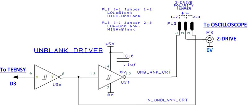
FIGURE 7. Schematic of Z axis driver.
Note: If your scope lacks a Z input, the TGI will still work, but the display will not be as crisp since you’ll be seeing all the point-to-point transition lines.
You’ll also see a bright “last spot plotted” dot where the CRT beam was parked while waiting for the next refresh cycle to begin.
Powering the TEENSY Graphics Interface
The TGI requires an external source of regulated +5 VDC (plan on 500 mA) and ±12 VDC (plan on 50 mA). The schematic for the power input circuits is shown in Figure 8. A simple Arduino-style wall-wart AC adapter or cell phone USB charger plug works fine as the +5 VDC source. However, the ±12 VDC must come from a low noise, clean, linear-regulated supply.
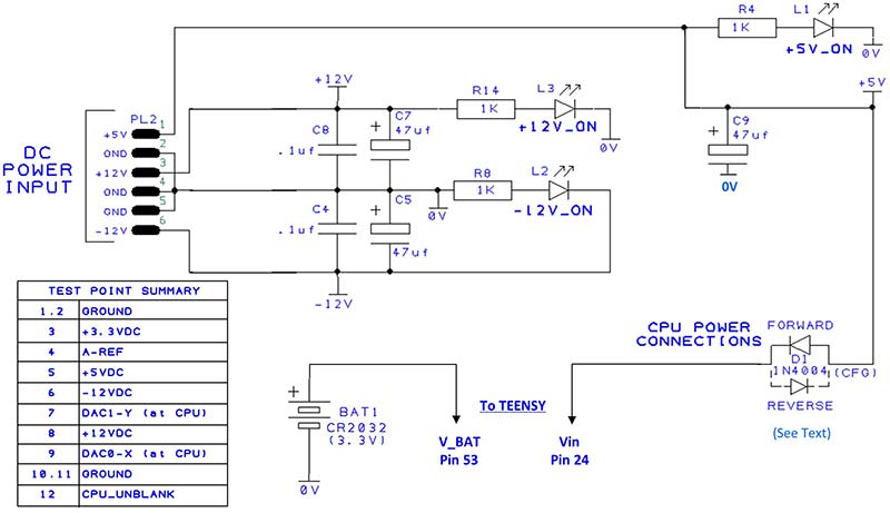
FIGURE 8. Schematic of power input and test point assignments.
My efforts to try some inexpensive switching power supply modules to convert the +5 VDC into a ±12 VDC supply for the op-amps failed miserably as the resulting scope display was fuzzy and jumpy. In a word, the image quality was TERRIBLE! The 50-100 mV of high-frequency switching noise present on the low-cost ±12V inverter outputs was enough to wreak havoc on the display. Only clean linear supplies yield good display quality. See the BUILD documents available with the downloads for a few power supply sources and approaches that I found worked well.
3.3V Battery: The TGI PCB includes a holder for a CR2032 lithium battery. This battery connects directly to the TEENSY and provides backup power that keeps the onboard real time clock (RTC) ticking when CPU power is off. This is a key requirement for any digital clock (think of your VCR endlessly flashing 12:00!).
Diode D1 Notes: Diode D1 provides important power protection between the TGI and your PC. There are two installation options for D1 depending on how you power the TGI/TEENSY CPU combination. Most likely, you will be using the “forward” orientation, but please read through the BUILD documentation to choose the correct orientation for your power supply plan.
Building the TGI Circuitry
As shown, the TGI circuitry is simple and straightforward. As such, the interface circuits can be easily fabricated using point-to-point wiring and a small solderless breadboard. However, since I wanted to create a more stable and easy-to-build unit, I used DesignSpark 8.1 PCB to create a two-layer (all through-hole components!) printed circuit board (PCB) layout. The PCB (available through the Nuts & Volts JunkBox webstore) makes building the TGI a snap.
The assembled board is shown in Figure 9, with the complete Parts List shown in Figure 10. I’ve provided Digi-Key part numbers for one-stop shopping. However, all parts are also readily available from other distributors and eBay suppliers.
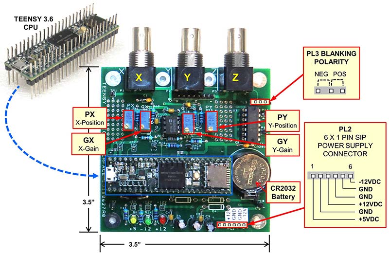
FIGURE 9. TGI circuit board.
PARTS LIST
| Item |
Ref Designators |
Qty |
Description |
Value |
Digi-Key # |
| 1 |
R24,R3,R7,R17,R1,R2,R13 |
7 |
USE JUMPER WIRE - SEE BUILD DOC FOR PLACEMENT and OPTIONS |
0_ohm |
N/A |
| 2 |
TP11,TP10,TP2,TP1,TP7,TP9,
TP12,TP6,TP8,TP5,TP3,TP4 |
12 |
ONE-PIN .025” SQ MALE TEST POINT |
FOR TEST USE ONLY. CAN USE SHORT WIRES OR .025 SQ PINS CUT FROM PIN STRIPS. |
SAM11363-ND |
| 3 |
PL3 |
1 |
THREE-PIN .025” SQ MALE .100 SIP TIN |
OPTIONAL - CAN USE JUMPER WIRE. |
SAM9525-ND |
| 4 |
PL2 |
1 |
SIX-PIN .025” SQ MALE .100 SIP TIN |
CONN HEADER 6-POS .100” SNGL TIN. |
SAM1035-06-ND |
| 5 |
PL1 |
1 |
EIGHT-PIN .025” SQ MALE .100 SIP TIN |
ONLY USED W/CHASSIS MOUNT BNCs. |
SAM1035-08-ND |
| 6 |
R5,R23 |
2 |
10-TURN OP ADJ,10K OHM 0.5W TH |
10K |
490-2875-ND |
| 7 |
R9,R18 |
2 |
10-TURN OP ADJ, 100K OHM 0.5W TH |
100K |
490-2876-ND |
| 8 |
U3 |
1 |
IC HEX SCHMITT-TRIG INV 14-DIP |
74LS14 |
296-1643-5-ND |
| 9 |
D1,D2,D3,D4 |
1 |
DIODE GEN PURP 400V 1A DO41 |
1N4004 - ONLY INSTALL D1. OMIT D2, D3, and D4. |
1N4004-TPMSTR-ND |
| 10 |
L3,L2,L1 |
3 |
3 MM LED, 0.1” LD SPACING (Shows ON status for each voltage) |
PCB MOUNT 3 MM LED .100 LS. COLOR IS BUILDER’S CHOICE. |
VARIOUS |
| 11 |
P1,P2,P3 |
3 |
PCB MOUNT RT ANG BNC |
USE CHASSIS MOUNT BNCs IF DESIRED |
A97555-ND |
| 12 |
C8,C10,C2,C4,C3 |
5 |
CAP CER 0.1 µF 50V AXIAL |
.1 µF, 50V CERAMIC |
587-5501-1-ND |
| 13 |
U2 |
1 |
IC OP-AMP GP 4.5 MHz EIGHT-DIP |
CA3240 |
CA3240EZ-ND |
| 14 |
C7,C5,C9 |
3 |
CAP ALUM 47 µF 20% 50V RADIAL |
47 µF, 50 V .1” LS |
P10321-ND |
| 15 |
BAT1 |
1 |
BATTERY HOLDER |
FOR CR2032 BATTERY |
BS-D-ND |
| 16 |
R14,R4,R8 |
3 |
RES 1K OHM 1/4W 1% AXIAL |
1K |
1.00KXBK-ND |
| 17 |
R11,R21,R12,R19 |
4 |
RES 4.7K OHM 1/4W 5% AXIAL |
4.7K |
4.7KQBK-ND |
| 18 |
R6,R15,R16,R22 |
4 |
RES 10K OHM 1/4W 1% AXIAL |
10K |
10.0KXBK-ND |
| 19 |
R10,R20 |
2 |
RES 68K OHM 1/4W 1% AXIAL |
OMIT - ONLY REQ’D WHEN USING UNIPOLAR OP-AMP PWR SUPPLY. |
68.0KXBK-ND |
| 20 |
U1 |
1 |
TEENSY 3.6 CPU MODULE |
TEENSY 3.6 CPU |
1568-1442-ND |
| 21 |
BATTERY |
1 |
CR2032 |
3.3V LITHIUM BATTERY |
P121-ND |
| 22 |
8-PIN DIP IC SKT |
1 |
SOCKET FOR U2 |
OPTIONAL BUT RECOMMENDED |
VARIOUS |
| 23 |
14-PIN DIP IC SKT |
1 |
SOCKET FOR U3 |
OPTIONAL BUT RECOMMENDED |
VARIOUS |
| 24 |
FEMALE SKT STRIPS |
3 |
40-PIN .025” FEMALE SOCKET STRIP |
CUT and FILE AS NEEDED FOR U1. |
VARIOUS |
| 25 |
SIX-PIN WIRE HARNESS CONNECTOR |
1 |
SIX-PIN .025” SQ FEMALE CONNECTOR |
PART OF WIRE HARNESS BETWEEN TGI PCB AND POWER SUPPLY. |
VARIOUS |
| 26 |
TWO-PIN FEMALE JUMPER |
1 |
UMPER FOR USE ON PL2 TO SELECT BLANKING POLARITY |
TWO-PIN JUMPER; CAN USE WIRE-WRAP WIRE OR SOLDERED JUMPER WIRE. |
VARIOUS |
| 27 |
BNC M-M CABLE |
3 |
BNC (M) to BNC (M) COAX CABLE |
LENGTH DEPENDS ON PHYSICAL SETUP |
VARIOUS |
| 28 |
BLANK PCB BOARD |
1 |
20180627R0 (Rev 0) |
BLANK PCB |
NV WEBSTORE |
FIGURE 10. TGI Parts List.
A Few Assembly Notes
The online BUILD instructions detail the assembly, test, and adjustment steps to help you get your TGI up and running. Be sure to install the “0 ohm” jumpers and the single 1/2 inch jumper wire as directed in the document.
By installing female socket strips into the TGI board and male pins into the TEENSY 3.6, the CPU can plug into the TGI PCB creating a nice and compact package. If you install “long male pins” (~20 mm overall pin length) into the CPU board, top-side access to all the TEENSY I/O ports is retained for connections to other circuits or shields in your project.
Three coax connectors mounted on the TGI are provided so that standard shielded male-to-male BNC cables can be used to connect the TGI board to the inputs of your analog oscilloscope. Optional connector PL1 is available to wire to off-board chassis-mounted BNC connectors if you prefer.
Lastly, take note that for those so inclined, some uncommitted .1 x .1 grid breadboard space has been provided on the TGI board for builder tweaks, additions, and innovations.
Getting Started with the TEENSY & CRT_SCOPE_CLOCK.ino
Just like any other Arduino project, the TGI system is programmed using the Arduino IDE 1.8.5 or later. You’ll need to download and install the Arduino IDE as well as the TEENSY support programs and libraries. Once you have the TEENSY support programs installed, you simply select the processor type, port, and CPU clock speed (Figure 11).
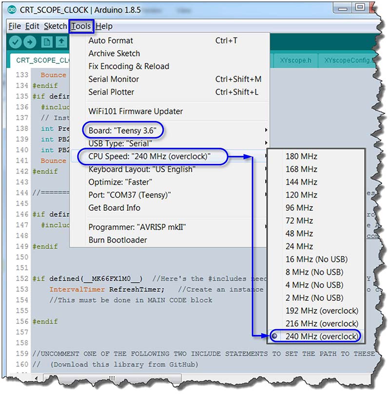
FIGURE 11. Processor and CPU clock speed selection.
One of the nice things about the TEENSY is that many CPU clock speeds can be selected. For this project, faster is better, so I recommend running at the 240 MHz overclock setting.
If this is your first Arduino TEENSY project, I suggest you start out with some basic “hello world” and “blinking LED” test programs to get the IDE set up, compiling, and properly connected to your TEENSY. Once you have the IDE operational and have completed the TGI build and preliminary checkout, you’ll be ready to plug the TEENSY 3.6 onto the TGI PCB and connect it to your oscilloscope.
After you install the XYscope library into your IDE, you just need to open the CRT_SCOPE_CLOCK.ino program in the “examples” folder. Although the code may look a bit complex, a detailed review reveals the standard Arduino structure as shown in Figure 12.
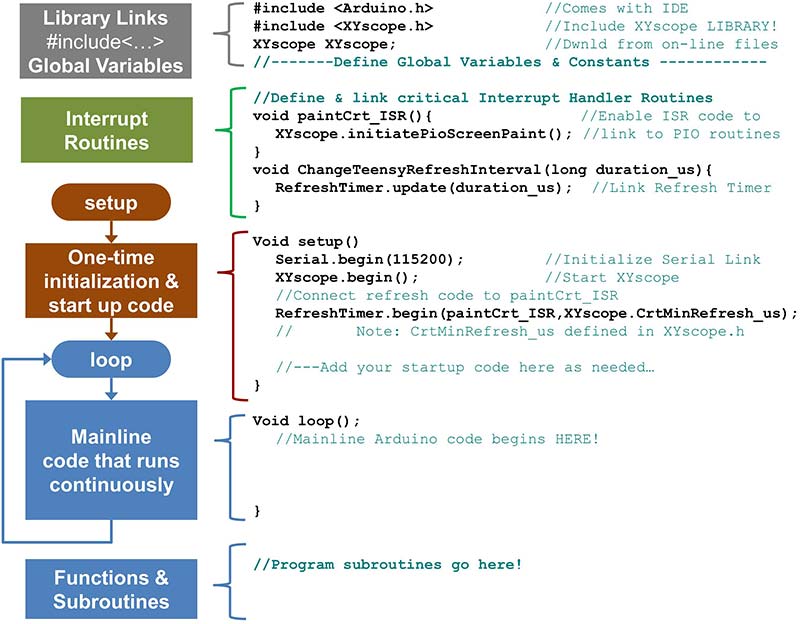
FIGURE 12. Basic program structure of CRT_SCOPE_CLOCK.
A test compile of the program will show if you have all the libraries installed and the correct processor options selected. If there are no compiler errors, simply click the compile & upload button. Note: There are some peculiarities to the TEENSY loader; please check out the TEENSY website for further help if needed.
#Include Files
All Arduino programmers are used to the #include<___.h.> instruction as this is the method utilized to add the libraries’ routines (such as XYscope!) into your code set.
Two additional files that are “included” are HersheyFontROM.h and VectorFontROM.h. These are actually data tables that define the two character sets available for plotting text to the screen (see Figure 13).
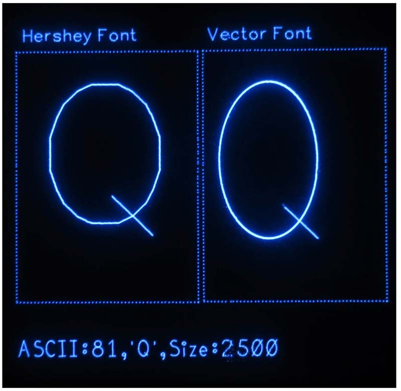
FIGURE 13. Two font styles are available for the type.
XYscopeConfig.h is another “included” file that is used to define default values and constants (like port assignments), as well as set startup switches to control XYscope library options (such as default font selection). The reader is encouraged to read through this file and try other options and settings. There are also a couple of switches at the top of the XY_SCOPE_CLOCK.ino file to control the clock display format. This enables the user to specify a “pure analog display” (just a clock face and hands) or hybrid display which adds a digital time display along with day of week and date text.
Up and Running
Once CRT_SCOPE_CLOCK has been uploaded to your TEENSY/TGI system, the program will auto start directly into CLOCK mode. In all likelihood, the first time in, things won’t look great on your oscilloscope display. You’ll need to exit CLOCK mode to get at the test and setup options.
With your PC linked to the TEENSY, open the IDE serial monitor (Tools>Serial Monitor) and enter ‘?↵‘; this will exit the CLOCK mode and you’ll see the menu of Figure 14 appear in the serial monitor. Use the online BUILD documentation for guidance to these options, as well as detailed gain and position potentiometer setup procedures.
========= CRT_SCOPE_CLOCK(3.20)  =========<br />
H/h/? = Show HELP Screen & plotting STATS<br />
---- TEENSY Hardware Settings & Control -----<br />
  nn S = Set LARGE-step DAC SETTLING (n=count,0-100)<br />
  nn s = Set SMALL-step DAC SETTLING (n=count,0-100)<br />
nnnn L = Set LARGE-step Threshold LIMIT (n=count,0-4095)<br />
  nn U = Set UNBLANK Width (nnn=count,0-50)<br />
     I = Show current HW settings on Scope Screen<br />
   n E = EEPROM, n=0 EEPROM->Screen,<br />
         n=1 EEPROM->Active Dataset,<br />
         n=10 SAVE Active_Dataset->EEPROM)<br />
---- SCREEN SAVER Test routines<br />
     W = Wakeup from SCREEN SAVE<br />
 nnn W = Change Screen Save Timeout (n=Seconds)<br />
---- TEXT Test routines<br />
     m = Toggle Text Spacing Mode, Mono<-->Prop<br />
     M = Toggle FONT Select, Vector<-->Hershey<br />
 nnn t = Set TEXT Intensity n=1-250%
---- GRAPHICS Test Routines ----<br />
 nnn G = Set GRAPHICS Intensity n=1-250%<br />
     K = CLEAR Display<br />
xxxx,yyyy Z = ADD a point at X,Y to Display List<br />
---- TEST Patterns & Demos ----<br />
     P = Display 'Show Test Patterns' sub Menu<br />
  nn P = Display Test Pattern Number 'n'<br />
---- CPU Performance Benchmarks ----<br />
     d = Run DHRYSTONE Test (can take >60 Sec)<br />
---- SET TIME & DATE ----<br />
 h,m,s T = Set time values (hours,min,sec)<br />
 m,d,y D = Set date values (month,date,year)<br />
       Q = QuickSet Time & Date w/Push Buttons<br />
==========================================<br />
 STATS..............<br />
  MaxBuffSize: 34900  Total Array Used: 8037 (23 %)<br />
  TNSY Dac_Vref=1.5V<br />
  TEENSY Clock:240 MHz, PIO Paint Time: 10.60 ms<br />
  Refresh Interval: 20.00 ms, Refresh Rate: 50.0 Hz<br />
  Small-Step Settling: 25  Large-Step Settling: 50<br />
  Pio Unblank:8  Big-Step Threshold:1000<br />
  Refresh Load: 53.0%, Compute Availability: 47.0%<br />
  Avg Point Period: 1.32 us<br />
  Graphics Int: 100 % (10)  Text Int: 100 % (10)<br />
  Font Spcng Mode = MONO, Scrn_Sav_Secs: 600<br />
RDY->
FIGURE 14. CRT_SCOPE_CLOCK monitor interface.
Once the gain and position pots are adjusted, you can explore the demo screens and more advanced options to optimize DAC settling times and UNBLANK pulse widths.
Adding a Control Panel
While time and date (and many other adjustments) can be set through the IDE MONITOR program, the code is all ready for stand-alone operation using a little control panel. As seen in Figure 15, simply wire four pushbuttons to TEENSY ports D4-D7 and you’ll be good to go!
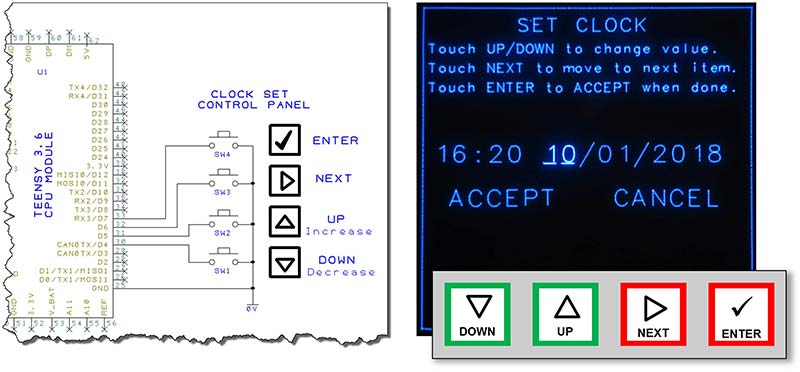
FIGURE 15. CRT clock control panel and SET CLOCK display.
While in the CLOCK mode, just touch any button to enter SET CLOCK mode. Use the UP (↑), DOWN (↓), and NEXT (→) buttons to navigate; touch ENTER (✓) to lock-in your settings.
Updates
As time goes on, I expect there could be new demos or other updates for this project. I will post any updates to my Github repository and the N&V downloads package. Stop in at these sites periodically to check for updates.
Room to Play!
This retro-tech CRT clock is a neat way to demonstrate computer graphic principles and show how new-age microcomputers can merge with old-school CRT displays to create a “steam-punk thingy that can tell time.”
You can use the clock demo as-is to get started, but I encourage you to consider some feature upgrades such as a more artful clock face, graceful clock hands, tick-tock sounds, and alarm functions. Get clever and extend CRT phosphor life by using a motion sensor to unblank the CRT only when someone is nearby.
There’s lots of room to play, only bounded by your imagination! Of course, this project can also be a platform for education, instrumentation, computer games, or other projects that can leverage vector graphics technology.
Best of luck and happy plotting! NV
I’d like to thank Greg Kovacs for introducing me to the TEENSY CPU and his challenge to port the XYscope concept to the TEENSY CPU. I also want to extend my appreciation to Bill Esposito for his Hershey font code and other technical feedback.

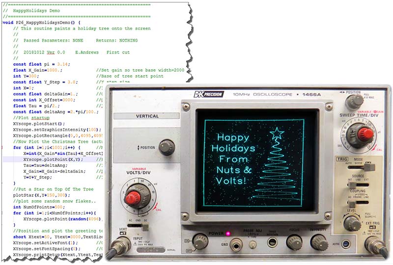
A. Here, we see that a damped sine wave equation can drive the XYscope.plotPoint(X,Y) routine to make a Christmas tree. Random numbers were used to plot “500 snowflakes” for a background.
B. In addition to the “Oscilloscope Clock” application, the CRT_SCOPE_CLOCK.ino example code includes many demonstrations to illustrate how the XYscope plotting library works. Here, we see how a recursive routine that plots a treebranch can call itself to make a whole tree.
REFERENCES
“The Arduino DUE Graphics Interface”
February & March 2018, Edward Andrews
https://www.nutsvolts.com/magazine/article/the-arduino-graphics-interface-part-1
https://www.nutsvolts.com/magazine/article/the-arduino-graphics-interface-part-2
Design Spark - Free PCB layout software
https://www.rs-online.com/designspark/pcb-software
Arduino IDE, Arduino libraries, and useful guides & references
https://www.arduino.cc
TEENSY 3.6 purchase, tech details, libraries, and lots of programming guidelines
https://www.pjrc.com/store/teensy36.html
AGI hardware details, software library, and sample programs
https://github.com/Ed-EE-Eng/XYscope
Downloads
What’s in the zip?
Source Code
Examples
Gerber Files