In the US, the DC volt is legally defined by the Josephson array — a super conducting quantum device with a highly repeatable output voltage. (The DC Volt, Nuts & Volts, Jan. ’97.) Banks of standard cells and temperature-stabilized zener diode references are used by the National Institute of Science and Technology (NIST) to calibrate DC meters for scientific and industrial customers. So how is the AC volt defined?
As it turns out, there is no “standard” AC volt in the same way there is a standard DC volt. Instead, the AC volt is defined by conversion to DC and comparison with a DC voltage standard.
The evolution of this conversion is another fascinating story in the quest for ever higher measurement accuracy. And, along the way, I’ll give you some pointers on building low-cost AC calibration equipment for your own shop or lab.
PRECISION RECTIFIERS
Although not as accurate as the thermal converters we’ll look at shortly, precision rectifiers are widely used. The circuits are in-expensive and quite good enough for “everyday” measurements. Many commercial AC meters are of this type.
The circuit in Figure 1 has been around for many years, but it can be made to perform very well.
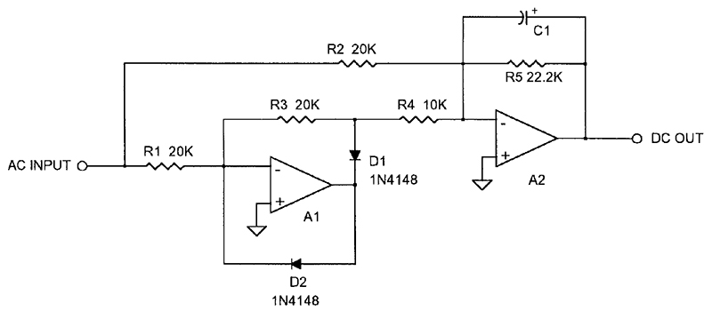
FIGURE 1. Precision rectifier. Typical resistor values shown aren’t critical, but should be closely matched for best accuracy (0.1% or better).
So how does it work? For positive input signals, diode D2 is off and D1 conducts. Thus, A1 is just a unity gain inverter. This signal is summed with the original input by A2, but because R4 is only 10K ohms, the A1 output is amplified by twice as much as the original input. When the input is negative, D1 is off and D2 conducts. This holds the inverting input of A1 at virtual ground and effectively removes A1 from the circuit. So A2 is an inverter producing a positive output of the same voltage as during the positive half-cycle input. R5 is chosen so that one volt RMS at the input gives a one volt DC output. And this brings up the interesting subject of average, root mean square (RMS), and peak value measurements.
Figure 2 illustrates these relationships; the peak and peak-to-peak values are easy to see and understand.
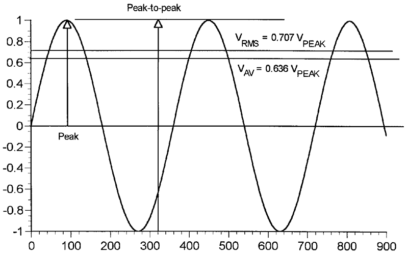
FIGURE 2. Sinewave relationship between peak, peak-to-peak, average, and RMS.
If all the instantaneous values are averaged over a half-cycle, the result is the average voltage. For a sinewave, VAV = 0.636 VPEAK. With R5 in Figure 1 equal to 20K ohms, the DC output would be the average value. But we usually find the RMS value to be more useful because it is a measure of the energy in the signal. Virtually all AC voltmeters read RMS volts although many are actually average responding (those that use rectifiers).
An AC RMS ampere flowing through a resistance produces the same amount of heat as a DC ampere, so this becomes the basis for defining an RMS volt. VRMS = 0.707 Vpeak. By taking the ratio of VRMS/VAV = 0.707/0.636 = 1.1116, we get a value of 22.2K ohms for R5 to make the Figure 1 circuit RMS responding (for sinewaves).
Crest factor is the ratio of peak-to-RMS values. This is 1.414 for sinewave inputs (1/0.707), but can be as high as five or more for random noise. Average responding voltmeters are calibrated for sine-wave inputs, but loose accuracy when used for other input wave forms (including distorted sinewaves).
There are many other precision rectifier circuits; some use opamps only and no diodes. One or two new designs or variations are published each year, and this is an indication of just how useful and widespread this function has become. Good places to look for new circuits are the “Design Ideas” section in EDN magazine and “Ideas for Design” in Electronic Design.
RMS CONVERTERS
An ideal RMS converter computes the average of the squared input over some averaging time interval and then takes the square root. That is:
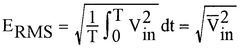
This looks worse than it really is because we can perform this operation electronically in a number of ways.
Many years ago, Ballantine Laboratories designed their model 320 True RMS Voltmeter. It used a series of biased diodes to approximate the “square” relationship between average and RMS. This worked well, but meter calibration was probably too labor-intensive for today’s market, so it has been replaced by other techniques. (There is an excellent discussion of how to approximate functions with diodes, including examples, in Nonlinear Circuits Handbook, published by Analog Devices.)
Now that multiplier ICs are common and fairly inexpensive, we can literally square, average, and then take the square root as shown in Figure 3. Analog Devices and Maxim Integrated Products have taken this approach one step further. Both companies make ICs that contain the whole RMS-to-DC converter, except for the averaging low-pass filter.
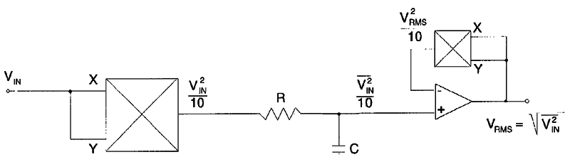
FIGURE 3. RMS-to-DC conversion with two analog multipliers. The multiplier in the amplifier’s feedback loop takes the square root. The line over a voltage denotes the average value.
Figure 4 shows a complete RMS voltmeter using an AD536A (or MX536A) and an off-the-shelf digital panel meter (DPM) for display. The AD536A needs only +5 volts for operation, but the DPM I used needed a floating nine-volt supply, so I had to use two nine-volt batteries. The low-pass filtering (averaging) is done by C2 and C4.
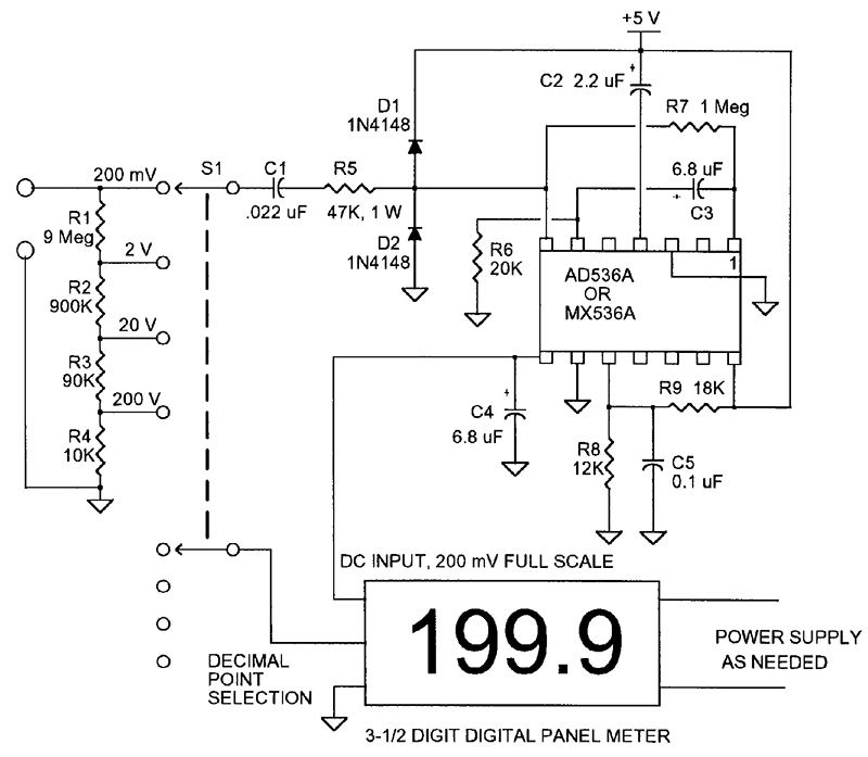
FIGURE 4. RMS voltmeter uses one integrated circuit and 3-1/2 digit DPM for display. All resistors except R5 are 1/4W, 1% metal film.
With the values shown, the DC error will be less than 1% of the reading down to about 10 Hz. The high-frequency response is set by the IC itself. The -3 dB bandwidth is 2 MHz for an input of one-volt RMS or larger, and 450 KHz at an input of 100 millivolts. For more details, ask the manufacturers for a complete spec sheet. You will also find a wealth of information, including this voltmeter circuit, in the Analog Devices booklet RMS-to-DC Conversion Application Guide. (The AD536A is available from Jameco Electronic Components.)
THERMAL CONVERTERS
A thermal converter consists of a resistance heater in contact with a thermocouple enclosed in an evacuated glass bulb (for thermal insulation). A photo of a typical unit from Best Technology, Inc., is shown in Figure 5.
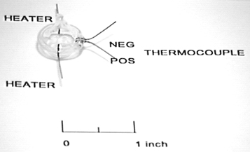
FIGURE 5. Model U.1 vacuum thermal converter from Best Technologies, Inc.; 5 mA through the 90-ohm heater generates a thermocouple output of about 7 mV.
Passing a current through the heater produces a voltage difference between the thermocouple leads. For this model, the output voltage is about seven millivolts for a five-milliampere heater current.
NIST uses thermal converters as “transfer” standards to calibrate AC voltage and current. In simplified terms, a known DC voltage is applied to a thermal converter’s heater and the thermocouple voltage is read. Then, an AC voltage is connected to the heater and adjusted for the same thermocouple voltage. Thus, the RMS value of the AC voltage is equal to the original (calibrating) DC voltage. In a sense, the DC voltage is transferred to the AC voltage.
Of course, in practice, there are many pitfalls and NIST is continually studying the various uncertainties and new converter designs. For ex-ample, the thermocouple voltage changes slightly when switched between DC and AC current. Also, the direction of the DC current can produce a small voltage difference. But these uncertainties amount to no more than 0.00005% (0.5 ppm) and are only of concern in maintaining the National AC standards.
Other uncertainties include Peltier effect errors and radio frequency pickup from other lab equipment or commercial broadcast stations. About one microwatt of heater power can produce 0.1% of rated output voltage in a typical five-milliampere thermal converter. They are rather sensitive to electromagnetic interference (EMI), especially at FM and TV frequencies. Short leads and short printed circuit traces will help minimize EMI pickup. Figure 6 graphs the AC-DC calibration uncertainty vs. frequency as posted on the NIST Web site at www.nist.gov.
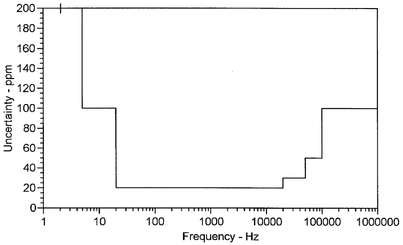
FIGURE 6. NIST AC-DC Calibration Uncertainty for voltages less than or equal to 100 volts, 1ppm = 0.00001%.
Even at relatively low frequencies — 50 KHz and up — shunt capacitance can cause measurable error. NIST has found that coaxial mounts for thermal converters and series voltage-dropping resistors are stable and predictable although perfect compensation is possible at only one frequency. Accurate voltage measurement becomes very challenging as the frequency increases to 40 or 50 MHz. Instead, power is measured using a thermal converter whose impedance is matched to the trans-mission line. If needed, the voltage can be calculated from the power and impedance.
Instrument manufacturers also use thermal converters in their RMS voltmeters. A typical circuit is shown in Figure 7.

FIGURE 7. Simplified diagram of thermal AC-to-DC converter. This circuit was used in the Hewlett-Packard Model 3403C True RMS Voltmeter.
Hewlett-Packard used this basic design in their model 3403C with the converters and associated amplifiers and filters in a heavy cast aluminum enclosure. Although no longer in production, the 3403C is noteworthy because it has a frequency response from DC to 100 MHz, and it will measure the RMS value of a combined AC, DC signal. The accuracy can be off as much as 10% of reading between 50 and 100 MHz, but it is 1% or better from DC to 1 MHz.
Let’s look at how this circuit works. The input signal voltage heats the thermocouple in TC1 producing a voltage at the non-inverting A2 input. A2, connected as a difference amplifier, zeros the voltage difference between its input pins by delivering just enough current to TC2 to null the output of TC1. In this application, the thermal converters must be a matched pair so they track with each other over the zero-to-full scale range of the meter. The aluminum housing provides thermal stability (long thermal time constant) and EMI shielding.
Figure 8 shows an AC-DC transfer calibrator you can build for home or lab use. It is based on a moderate-cost pair of matched thermal converters from Best Technology, Inc. Let’s take a look at how it works.
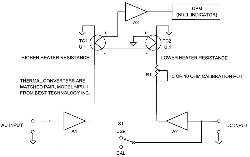
FIGURE 8. iiagram of AC-DC transfer calibrator you can build at home. Amplifier details are shown in FIgure 9.
With S1 in the CAL position, the input DC reference voltage is applied to both thermal con-verters through amplifiers A1 and A2, and R1 is adjusted for a null (zero voltage) on the DPM. The thermal converters are matched for equal output voltages for a five-milliampere heater current, but the heater resistance can vary 10% from its 90-ohm nominal value. I measured a pair at 87.8 and 91.9 ohms for a 4.1 ohm difference. R1 is a five-ohm pot in series with the thermal converter with the lower heater resistance. (You may need a 10-ohm pot depending on the heater resistance difference.)
Now S1 is flipped to the USE position and the AC voltage to be measured is connected to the AC input terminals. Vary the AC voltage until the DPM again reads zero. The RMS value of the AC voltage now equals the DC calibration voltage to within ±0.1% or better. (Overall accuracy depends on your DC reference.) This is an audio frequency instrument and should be precise up to 10 KHz or so, depending on your circuit layout.
A1 and A2 are identical composite amplifiers as shown in Figure 9.
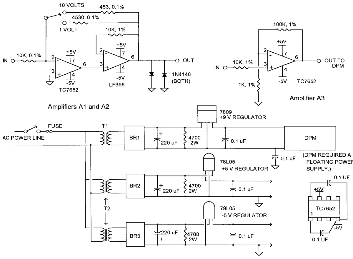
FIGURE 9. Amplifier and power supply detail for AC-DC transfer calibrator shown in Figure 8.
The input opamp is chopper-stabilized for low DC offset and good drift performance, but it won’t deliver five milliamperes to drive the thermal converter. Including a higher output current opamp in the feedback loop gives us the best of both worlds. A3 is also a chopper-stabilized opamp to give good null resolution on the ±200 millivolt scale of the 3-1/2 digit DPM.
This is a straightforward circuit, but I need to mention some precautions. A printed circuit board is essential; we’re dealing with microvolt differences from the thermal converters. For the same reason, solder the ICs and don’t use sockets. Each chopper opamp needs a pair of external capacitors to store the offset voltage correction. These should be good quality metalized polyester or polypropylene units. One side of each cap goes to the negative supply voltage and the printed circuit traces should go directly to pin 4. Chopper opamps are subject to lockup, but this won’t be a problem if you turn on the power supplies before applying a signal to either input. The diodes to common at the A1 and A2 outputs protect the thermal converters by limiting the heater voltage to about ±0.7 volt peak. The voltage-range switch should be a make-before-break type, and the A1 and A2 gain set resistors should be 0.1% or better. (Mouser Electronics stocks 0.1% metal film resistors with a temp-erature coefficient of 25 ppm at about a buck apiece in small quantities. And I’ve included a couple of precision resistor manufacturers in the Resources list.)
AN AC CALIBRATION SOURCE
If the AC-DC transfer calibrator is more than you need, you can still build a pretty simple AC voltage calibration source. The SWR300 is a precision sinewave reference IC from Thaler Corporation. It has an output of 7.071 volts RMS (±0.1%) over a programmable frequency range of 10 Hz to 100 KHz.
This output voltage is perhaps not too useful for meter calibration, but adding one opamp and a few precision resistors will give you 10 volts RMS which is a whole lot better. The frequency is set with two floating capacitors, so a four-pole switch is needed to change frequency. Also, below 1500 Hz, two external AGC (automatic gain control) capacitors are required which change value along with the frequency control caps.
For these reasons, I chose to build a fixed frequency reference (about 1000 Hz). The circuit is shown in Figure 10.
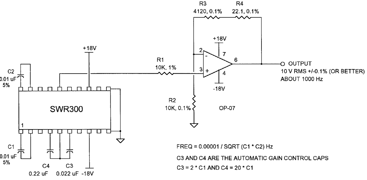
FIGURE 10. AC voltage reference using Thaler Corp. SWR300. Gain set resistors (R2, R3, R4) should be 0.1% or better with low temperature co-efficient.
The OP-07 opamp has a very low DC offset and a low enough output impedance to drive a 10K ohm Varley-Kelvin voltage divider. I measured the output total harmonic distortion (THD) as 0.35% which is important for calibrating average responding voltmeters. Note that a ±18 volt power supply is needed for a 10-volt RMS output (28.28 volts peak-to-peak). Both the SWR300 and OP-07 are rated for operation at this voltage.
I checked all my AC voltmeters with this calibrator and found everything within specs except one ... so it looks like I’ve got a repair job ahead! NV
RESOURCES
Precision Rectifier Circuits
EDN Magazine, 275 Washington St., Newton, MA 02158; Phone 617-964-3030.
Electronic Design Magazine, 611 Route 46 West, Hasbrouck Heights, NJ 07604; Reprints Phone 216-696-7000.
RMS-to-DC Converter ICs
Analog Devices, Inc., P.O. Box 9106, Norwood, MA 02062; Phone 800-262-5643.
Maxim Integrated Products, Inc., 120 San Gabriel Dr., Sunnyvale, CA 94086; Phone 408-737-7600.
Jameco Electronic Components, 1355 Shoreway Rd, Belmont, CA 94002; 800-831-5252.
Thermal Converters
Best Technology, Inc., 400 Boren Ave. N., Seattle, WA 98109; Phone 206-623-6135.
Precision Resistors
Mouser Electronics, 958 N. Main St., Mansfield, TX 76063; Phone 800-346-6873.
General Resistance, P.O. Box 185, North Branford, CT 06471; Phone 203-481-8937.
JBM Electronics, Inc., 1 Commerce Dr., Bedford, NH 03111; Phone 603-623-0446.
Micro-Ohm Corp., 1088 Hamilton Rd., Duarte, CA 91010; Phone 800-845-5167.
SWR300 AC Reference IC
Thaler Corporation, 2015 N. Forbes Blvd., Tucson, AZ 85745; Phone 520-882-4000.