How many times each day do you pick up a probe to measure a DC voltage? You probably don’t keep count and neither do I, but DC voltage is one of the most common measurements we make.
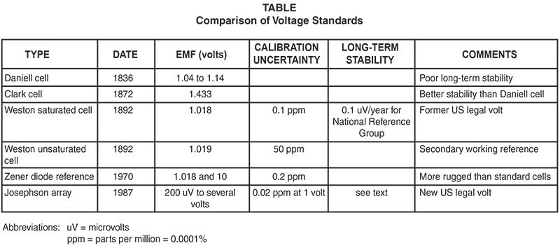
The meter reads, say 4.65 volts, and we usually accept it without question. But just what is a volt and how is it maintained? That’s the subject of this article and it’s a fascinating look at the search for increasingly more accurate methods of building a “standard volt.” This progression is summarized in the Comparison Table. There is a lot of math connected with this subject and I’m going to mostly leave it out as it’s not necessary to your practical understanding.
In 1881, it was agreed internationally at a Paris (France) meeting to define electrical units in terms of the basic mechanical units of length, mass, and time. The intention was to provide a consistent base for measurements in all branches of science and engineering but, unfortunately, it has proven to be a most difficult task — more on this as we go along.
In the United States, this effort is the responsibility of the National Institute of Science and Technology (NIST) and they do an outstanding job. (Prior to August 1988, NIST was the National Bureau of Standards (NBS) so many reports, monographs, and books bear the NBS name and publication number.)
THE CURRENT BALANCE
The current balance, shown in Figure 1, is a basic apparatus for defining the ampere. The current is adjusted so the position of the movable coil is balanced between the attraction of the fixed coil and the pull of gravity. The mutual inductance between the coils, the coil dimensions, the movable coil’s mass, and the acceleration of gravity relate the current to length, mass, and time. The current is also made to flow through a standard resistor, and so, by Ohm’s law, we have a “standard volt.” (We will ignore how we got the standard resistor, but it too is defined by the basic mechanical units.)
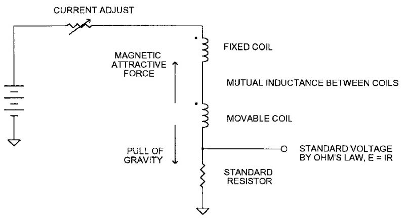
FIGURE 1. Current balance defines current (and voltage) in basic units of length, mass, and time.
Although simple in concept, the mechanical and electrical properties of the coils are very difficult to measure to the required precision. Winding strain and impurities in the wire introduce still more uncertainty. So, as the “maintained” volt has improved (see Table), NIST scientists have been hard pressed to keep up with the mass, length, and time verification. But let’s not get ahead of our story.
A current balance can define the standard volt, but it’s not a very convenient way to calibrate voltmeters. Some sort of battery with a fixed electromotive force (EMF) and excellent long term stability would be a lot easier to use.
STANDARD CELLS
Between 1879 and 1906, the volt was maintained in the US by a group of seven Clark cells, a battery using a zinc sulfate electrolyte. During these 27 years, the cell was improved by several workers, but it had limitations — such as electrode gassing — that couldn’t be overcome. Although not perfect by any means, Weston cells didn’t have the gassing problem and also had an EMF temperature coefficient that was 30 times better than the Clark cell. So by 1908, the Clark cells had been phased out in favor of the more stable Weston cells. In 1965, the National Reference Group of Standard Cells consisted of 44 saturated Weston cells in a temperature controlled oil bath. The temperature was maintained at 28° C within 0.01° C.
A cell is removed from the reference group if its EMF drifts by more than 10 microvolts from its previously steady value. When a cell is removed, the average (or mean) EMF for the group is recalculated starting from the date the removed cell was added to the group. Obviously, this calls for very good recordkeeping. But since the cell group is kept fairly large, the average EMF change caused by a cell removal is usually less than one microvolt.
By 1974, cell groups were kept in enclosures with a temperature instability of less than 20 microdegrees over several days. As often happens, the cell’s temperature coefficient became less important as temperature control technology improved. Ambient temperature changes now have a negligible effect on the cell EMF.
The sketch in Figure 2 shows a Weston standard cell, the only kind currently in use. “Saturated” refers to the cadmium sulfate solution; no additional cadmium sulfate will dissolve. Unsaturated cells are also used as secondary standards — more on this later.
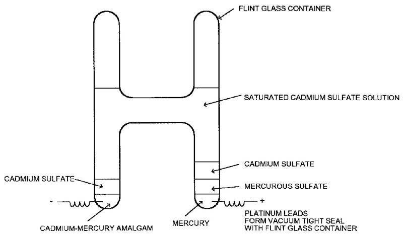
FIGURE 2. Sketch of Weston saturated standard cell. Average height is about 3-2/3” or 92 mm.
NIST goes to incredible lengths to insure the purity of each cell “ingredient” and the result is excellent stability with a long useful life. But saturated cells are finicky. They don’t like to be moved and if they are, they need a “rest period” at the new location for the EMF to settle down.
Also, they are not current sources. A discharge current of even one microampere for a few seconds changes the EMF for several minutes after the load is disconnected. A current as large as a milliampere can completely destroy the cell’s usefulness.
So how can we use them to make practical voltage measurements?
THE POTENTIOMETER
The answer is an instrument which draws only a very brief, minute current from the cell: a laboratory potentiometer. I have diagrammed a simplified potentiometer in Figure 3 to show you how they work. The working battery is typically a two- to four-volt storage battery. The voltage isn’t critical as its only job is to supply a stable working current. R3, a compensation adjustment, is first set to the EMF printed on the standard cell’s label. With S1 in the “std. cell” position (as drawn in Figure 3), switch S2 is tapped and R1 is adjusted for no deflection on the galvanometer. In most potentiometers, this sets full scale to 1.6 volts (voltage drop between points one and three) because the voltage drop from point one to point two exactly balances the standard cell’s EMF.
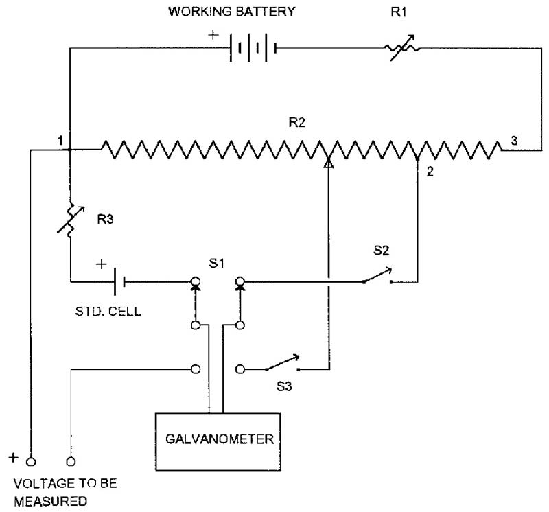
FIGURE 3. Simplified potentiometer. Working current is adjusted so voltage drop from 1 to 2 equals the standard cell emf.
To measure an unknown voltage, S1 is placed in the “down” position and switch S3 is tapped as the main dial (R2) is adjusted. R2 is a range switch in series with a long slidewire mechanically arranged in a spiral. Because of this length, any voltage between zero and 1.6 volts can be measured with a resolution of 10 microvolts. Higher voltages are handled with an accurate voltage divider called a “volt box.”
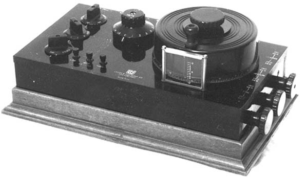
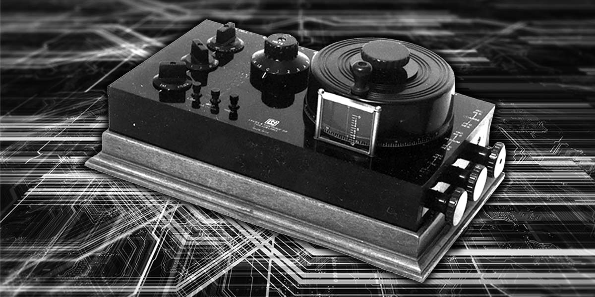
FIGURE 4. Leeds and Northrup Model 7552 is a typical potentiometer. Input and output binding posts are on rear panel (not visible). Large “drum” with crank handle is the spiral slidewire.
Manufactured by companies such as Leeds and Northrup (L&N), Julie Research Laboratories, and Weston Instruments, and traditionally housed in a well crafted wooden box with a highly polished bakelite control panel, a potentiometer is a precision instrument and must be treated accordingly. In this day of many-digit digital voltmeters (DVMs), manual-balance potentiometers can appear on used-equipment dealer’s shelves at bargain prices. A photo (Figure 4) of the author’s L&N model 7552 is typical of the breed.
TRANSFER STANDARDS
Saturated reference cell groups in their constant temperature enclosures are difficult and expensive to move between laboratories for intercomparison. It was done for many years simply because there was no alternative. But starting about 1970, solid-state voltage references were introduced for this use, that is, as transfer standards. They are much more rugged than cells and are easier and less expensive to ship.
The solid-state units use several zener diode voltage reference modules in a constant temperature enclosure. Batteries supply power to the reference modules and temperature control during transportation.
The zener diode modules often supply 10 volts (which is preferred for calibrating digital voltmeters), as well as 1.018 volts which is compatible with existing potentiometers.
As an added advantage, some zener units can supply some output current with no loss of accuracy or need for a recovery period.
Unsaturated Weston cells are not quite as accurate, stable, or long-lived as saturated cells. But they are less expensive and can be economically shipped by common carrier. They find use as secondary standards at schools and calibration laboratories.
Standard cells have been in use for over a hundred years, but the search goes on for an even more accurate standard. In 1987, work began at NIST to maintain the US (legal) volt with a Josephson array.
THE JOSEPHSON ARRAY
In the 1960s, British physicist Brian Josephson predicted that a radio-frequency (RF) signal directed through a “sandwich” consisting of a superconductor, an insulator, and a superconductor, would produce a specific, repeatable voltage. This sandwich is now known as a Josephson junction. This is a quantum device with a junction voltage given by:
Vn = nfh2e
f is the frequency of the RF excitation signal, e is the charge of an electron, and h is Planck’s constant. Both e and h are fundamental constants, but this isn’t sufficient to tie this volt definition to length, mass, and time.
Primarily because of the physical size of practical Josephson junctions, the RF frequency is 94 to 96 GHz. Substituting into the above equation (for n = 1) gives a junction voltage of about 200 microvolts. The integer “n” varies with the DC bias current and RF excitation power. Still, many junctions in series, that is a Josephson array, are needed for a practical standard. NIST has built various size arrays to over 2,000 junctions with larger ones planned.
Individual junctions are quite small and are getting smaller as research continues on superconducting materials. NIST researchers hope to eventually produce a chip with one million junctions in one square centimeter.
There are several reasons for wanting smaller arrays. The cooling system can be smaller, there will be a lower temperature gradient across the array, and equally important, a small size makes it easier to equalize the microwave power into each junction. Equal power into each junction is needed to keep n (in the above equation) the same for the whole array.
A Josephson array standard is diagrammed in Figure 5 and you can see that it’s not an instrument you could easily build at home!
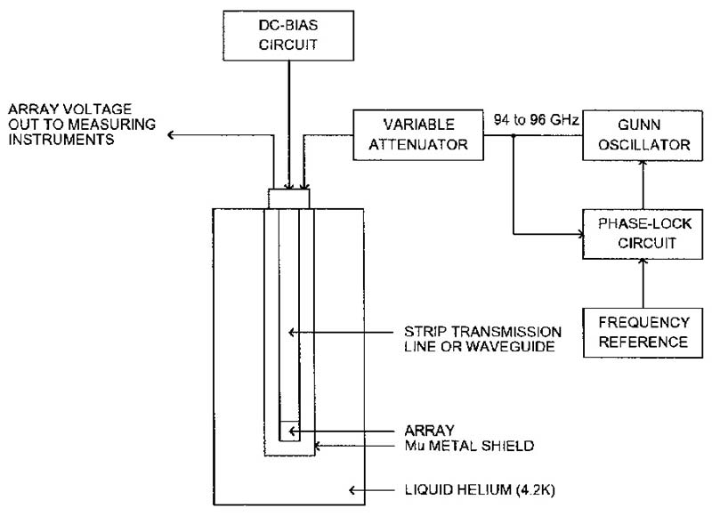
FIGURE 5. Josephson array DC voltage standard.
In April 1996, NIST announced a transportable 10-volt Josephson calibration system. Its weight and size are considerably smaller than previous models, yet it holds enough liquid helium to operate for six to eight weeks. The final version of this system is designed to be cooled with a refrigeration unit.
Although it is constructed as a physical instrument, the Josephson effect is fundamentally different from a standard cell or a zener reference. Some Josephson arrays can “go bad” for, as yet, unexplainable reasons, but new arrays can be built. For these reasons, the long term EMF stability is “perfect” (at our current level of understanding the process). Why then are we concerned with verifying this volt definition in terms of the basic mechanical units?
The problem lies in our imperfect knowledge of e and h, the electron charge, and Planck’s constant. The volt defined by the Josephson effect has excellent long-term stability, but is this volt the right “size?” An independent measurement will either confirm the size of the volt or let us adjust e or h to bring the measurements into agreement.
A very sophisticated superconducting current balance has been built to determine the “absolute ampere.” Also, work is continuing on a liquid electrometer for a direct absolute volt determination. In this apparatus, the vertical displacement caused by electrostatic attraction between a fixed plate and the surface of a mercury pool is measured by a laser interferometer.
But the difficulties in making these verification measurements are illustrated by several experiments with the above instruments, in which the residual uncertainties are about the same size as the Josephson volt uncertainty. That is, the results are inconclusive.
And so this interesting and challenging work goes on!
A VOLTAGE REFEENCE YOU CAN BUILD
If you want your own secondary voltage reference, here’s a suggestion for one that’s pretty good and easy to build.
Several companies are now producing zener diode references with a laser-trimmed buffer amplifier in an easy-to-use integrated circuit with a precise output voltage. I have evaluated many of these devices, and the best ones I’ve found are manufactured by Thaler Corporation (see Resources). Their VRE305A has a five-volt output with an initial error of not more than 500 microvolts (±0.01%) and a maximum temperature coefficient of 0.6 ppm per degree C — in an eight-pin DIP.
The circuit in Figure 6 will give you outputs of 1.018 and 10 volts. The specified 10,000 ohm resistors can be matched to 0.01% (1 ohm) with a 4-1/2 digit (or better) digital multimeter. (The actual resistance isn’t important, just the match.) The chopper-stabilized opamps will each contribute no more than five microvolts uncertainty to the output voltage.
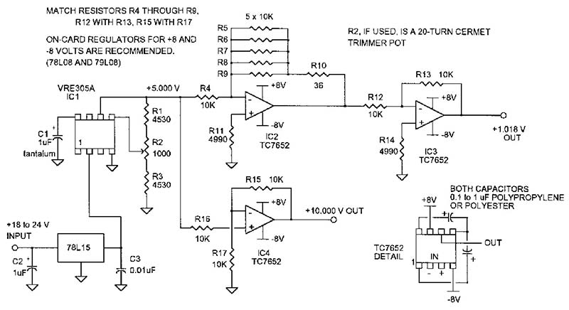
FIGURE 6. Suggested circuit for a voltage reference using a VRE305A and three chopper-stabilized opamps. All resistors are 1% metal film and some of the 10K resistors are matched to 1 ohm, as indicated above.
If you build several of these circuits and put them in a temperature-controlled box, you’ll get improved long-term stability. You will also be able to intercompare their EMFs to get an idea about their drift rates. The output drift of the different units should be uncorrelated (that is, independent) so the mean EMF for the group will tend to remain constant. Adding a sealed lead-acid battery pack and a charging power supply would give you power line independence and portability. It just depends on what you need or want.
Here are a few construction suggestions.
Use a PC board and then support the board by its wire leads to minimize strain-produced stray EMFs. If this is a mechanical problem, design the enclosure so the board slides into sidewall slots or use some support that puts no tension or compression on the board.
Carefully solder the ICs to the board; don’t use sockets. Don’t leave out the +15 volt regulator (78L15). This preregulation virtually eliminates supply voltage variation in the VRE305 output and helps insure uncorrelated outputs if you plan to use multiple reference boards.
Use one percent or better metal film resistors with the lowest temperature coefficient you can find, even if you are going to use a temperature-controlled box. Stand the resistors up off the board’s surface so you can use a copper alligator clip as a heatsink during soldering.
This is a DC circuit, so a bit more stray capacitance isn’t going to matter. The trim components (R1, R2, and R3) are optional. Using these resistors will give you about one millivolt of adjustment, but the five volts will be within 500 microvolts without them. Un-less you have a good DVM, you may be better off without the trim. This is a basic “building-block” circuit and I’ve had very good results with it. NV
Editor's Note - While this article was first published in Nuts & Volts back in 1997, the principles are still the same even though battery technology may have changed. If any readers have insight or experience to share that would update the information, feel free to share in the comments.
RESOURCES
A good source of information on standard cells is NBS Monograph 84, Standard Cells: Their Construction, Maintenance, and Characteristics. A photocopy can be ordered from National Technical Information Service, 5285 Port Royal Road, Springfield, VA 22161 as publication number COM7210513/LL.
Many NIST papers on DC voltage standards and calibration have been published in the IEEE Transactions on Instrumentation and Measurements. You should be able to find a complete set of back issues at any large library, especially college and university libraries.
To keep up with what is going on at NIST, in general, you can get a free E-Mail subscription to the NIST email newsletter by subscribing at www.nist.gov.
The VRE305A voltage reference is available from the Thaler Corporation, 2015 N. Forbes Blvd., Tucson, AZ 85745. (520) 882-4000.
The TelCom TC7652 chopper-stabilized opamp can be found at Digi-Key Corporation, 701 Brooks Ave. South, Thief River Falls, MN 56701, (800) 344-4539.