You should hear what you’ve been missing!!
The most unbiased source of international news today is shortwave radio. The propaganda style of the cold war is mostly gone. Stations such as the British Broadcasting Company, Radio Canada, Radio Netherlands, Deutch Welle (Germany), and The Voice of America are supported by governments instead of corporations. The countries are often surprisingly honest about themselves and about the state of the world. For instance, Radio Netherlands frequently talks about legalized prostitution in that country.
Many shortwave stations can be heard on the Internet using Real Audio software, but a fast connection is needed for uninterrupted streaming of audio. News programs are usually offered in five-minute segments which must be selected one at a time. An Internet connection and possibly a phone line has to be tied up while listening. This is a different experience than listening to shortwave radio.
An English language shortwave broadcast can be found almost anytime during the day or night. There are many good shortwave receivers at reasonable prices on the market. The GlobeSpan radio presented here can be home-constructed, it requires little alignment, and its performance is impressive. The radio can receive AM (amplitude modulation), CW (code), and SSB (single sideband) and could be tuned to amateur radio bands with different tuning coils.
History
The original vacuum tube regenerative radio (a representative schematic is shown in Figure 1) was patented in 1914 by Edwin Armstrong.

FIGURE 1. Traditional tube-based regenerative receiver.
This was the primary design used in the early 1920s for broadcast radios. Because regenerative radios radiated a signal from the antenna that would give away the location of the receiver, they were not practical for military uses. Interference with other receivers also led to the design being supplanted by the tuned radio frequency (TRF) radios in the 1920s. Shortly after inventing the regenerative receiver, Armstrong started working on the superheterodyne receiver which replaced the TRF radios for broadcast receivers around 1930.
The main advantage of the regenerative radio is that a complete receiver could be implemented with a single vacuum tube (using headphones and battery power). The regenerative circuit remained a favorite design for home-constructed shortwave broadcast radios and amateur receivers throughout the 1930s. From the 1940s on, regenerative radios (mostly tube based) have been offered in commercial kits and have been the subject of numerous magazine construction articles. There have been no commercially-constructed versions, probably because of the difficulty of obtaining FCC-type approval on a receiver that is expected to radiate spurious signals.
The superheterodyne receiver has undergone years of research and virtually every receiver today uses this principle. In contrast, the regenerative radio has seen little development and contemporary designs are not much different than the original Armstrong design (similar to Figure 1). The author's regenerative radio presented in the March 1994 issue of Popular Electronics, broke with tradition and offered many improvements over the old design. The GlobeSpan radio presented here has additional technical and cosmetic improvements over the 1994 version. A list of improvements is given below in Table 1.
| 1. In traditional regenerative receivers, the antenna was connected directly to the tuning circuit through an antenna trimmer capacitor (see Figure 1). Oscillations from the receiver would be radiated from the antenna. Antenna isolation in the GlobeSpan greatly reduces radiation. |
| 2. Because of the antenna connection mentioned above, when the antenna trimmer setting was changed or a different antenna was attached to the receiver, stations would shift to different locations on the dial. Providing a dial calibrated in frequency would have been impossible. A 0 to 100 log dial was provided and this had limited usefulness. In the GlobeSpan, the location of a given station on the dial will remain the same regardless of antenna characteristics. The GlobeSpan dial can be calibrated in frequency, if desired. |
| 3. Traditional regen receivers were general coverage and tuned 1.7 to 30 MHz with three or four plug-in coils. The GlobeSpan covers only one shortwave broadcast band (about 500 KHz) with each coil. Tuning is much easier and regeneration is stable over the shorter tuning range. |
| 4. In the GlobeSpan, a Colpitts circuit is substituted for the tickler coil oscillator. This allows the use of simple two terminal tuning inductors. Bandswitching is accomplished with a simple one pole switch. |
| 5. In the 1994 version of this receiver, commercial "off-the-shelf," two-terminal inductors were used. The GlobeSpan uses hand-wound powdered iron and ferrite toroidal inductors that provide more selectivity, a more uniform Q factor over the band, and a more constant regeneration setting over the band. |
| 6. Regeneration is controlled by changing the transconductance of a transistor. With this method, the frequency of the tuned circuit is independent of the regeneration setting. The technique of changing the transconductance of a pentode tube was known in the 1930s, but it was rarely used in regenerative receivers. |
| 7. Most traditional regen receivers had no independent volume control. Output level was controlled by the regeneration control which also affected the receiver bandwidth. In the GlobeSpan receiver, regeneration and volume are controlled by separate potentiometers. |
| 8. The GlobeSpan has an output for a frequency counter so that digital readout of frequency is possible. |
| 9. The GlobeSpan input impedance to the antenna is high. A short antenna will function like an active antenna. |
| 10. Traditional regen receivers had no RF gain control. The RF gain of the wideband amplifier of the GlobeSpan is switchable between 40 dB, 60 dB, and 80 dB. |
| 11. All GlobeSpan controls including main tuning, are DC operated. The bandswitch is located on the circuit board. All signals stay on the circuit board from the antenna input to the speaker wire. |
TABLE 1. GlobeSpan Receiver Improvements
Appearance
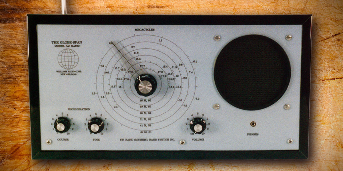
The GlobeSpan was originally conceived as a vacuum tube radio. Vacuum tube designs are costly and finding suitable parts is often difficult. A transistor design was subsequently chosen, but cosmetic factors were manipulated to give the radio an old fashioned appearance. The "breadboard" type construction popular in the 1920s was used. The name "GlobeSpan" was chosen to sound like but not duplicate any of the commercial radio names of the past (Transoceanic, Ocean Hopper, Space Spanner, etc.). The physical appearance of the radio is shown in Figures 2, 3, and 4.
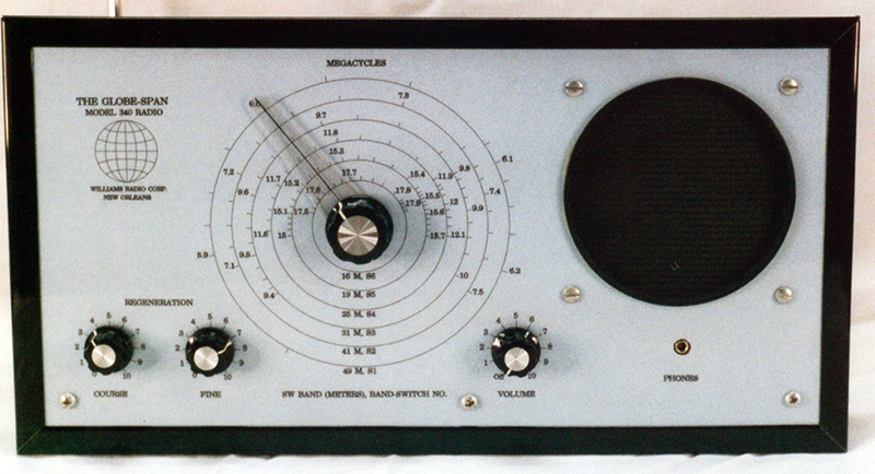
FIGURE 2.
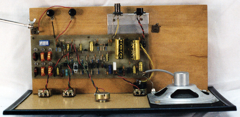
FIGURE 3.
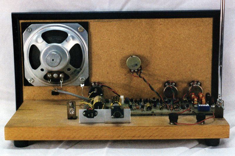
FIGURE 4.
Tuning and Performance
The regenerative radio is tuned by means of a single L-C circuit. Positive feedback (regeneration) is used to raise the quality factor (Q) of the L-C circuit to a value of 1,000 or more. This greatly increases the gain and narrows the bandwidth of the receiver.
The shape factor of the tuned circuit cannot be controlled as in the intermediate frequency (IF) stage of a superhet. Thus, it can be difficult with a regen to receive a medium level signal that is close in frequency to a very strong signal. A variable attenuator on the antenna can help with this situation. The GlobeSpan receiver does nicely in separating equally strong signals that are only 5 KHz apart.
Since the regen does not use frequency conversion, it cannot have the image frequencies characteristic of superhets. As the regen circuit is more sensitive to weak stations than to strong stations, it has an inherent function somewhat like the automatic gain control (AGC) built into most superhets. Using a four-inch speaker, the GlobeSpan provides a surprisingly good audio.
Circuit Description
The block diagram of the GlobeSpan receiver is shown in Figure 5.
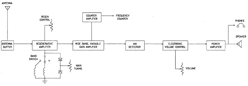
FIGURE 5. Block diagram of the GlobeSpan Receiver.
The schematic diagram is shown in Figure 6.

FIGURE 6. Schematic diagram of the GlobeSpan Receiver.
A regenerative receiver can be constructed using a single transistor. The extra transistors and ICs allow for speaker operation and for other improvements in performance.
The input is an antenna buffer that presents a high impedance to the antenna and results in a short wire acting like an active antenna. Following the antenna buffer is a high pass filter that attenuates medium wave stations and prevents overload by them. The signal then goes into gate 2 of transistor Q2. Thus, the antenna is doubly isolated from the tuned circuit.
The regenerative amplifier (Q2) tunes in the desired shortwave station. The traditional circuit shown in Figure 1 was originally called a "tickler coil oscillator" and later called a "tuned grid oscillator." A Colpitts oscillator was used in the GlobeSpan because it employs simpler inductors. Varactor diodes and a potentiometer were used for main tuning instead of a variable capacitor because mechanical variable capacitors are becoming expensive and difficult to find.
A secondary benefit of varactor and variable resistor control is that radio frequency (RF) currents are kept on the circuit board. The frequency controlling potentiometer carries only direct current (DC). A log potentiometer was used for the tuning control to compensate for the exponential characteristic of the varactors. The regeneration controls affect the gain and bandwidth of the amplifier. The course control is set so that regeneration occurs near the middle of the fine control's range. For AM stations, the control is set just below the oscillation point of the amplifier. The shortwave band is changed by switching between single two terminal inductors. The output of the regenerative amplifier stage is radio frequency (RF).
The output of the regenerative amplifier stage (Q2) is followed by four single transistor wide bandwidth RF amplifiers (Q3-Q6). By switching two of these amplifiers for either unity gain or 20 dB gain, the total gain can be changed from 40 dB to 60 dB to 80 dB; 60 dB is the most commonly used gain selection. The simple four transistor amplifier was much more stable than several variable gain IC amplifiers that were tried.
A frequency counter buffer and the AM detector follows the wide bandwidth amplifiers. A frequency counter allows for precise measurement of the received signal or of the frequency of oscillation of the regenerative amplifier stage. This is useful for making a frequency dial for the receiver and for setting the frequency limits of the shortwave bands by use of the trimmer capacitors C1-C6.
The AM detector is based on the infinite impedance design and it presents a fairly high input impedance to the final RF amplifier. The output impedance is low enough to drive the electronic volume control that follows. A silicon diode can be used in this circuit instead of the usual germanium diode which is becoming hard to find. The input source does not have to be referenced to ground as with other diode detectors. Otherwise, the performance of this detector is the same as other single diode types.
The electronic volume control keeps the audio signal on the circuit board. This enhances the stability of the receiver. The voltage across the volume control potentiometer is direct current.
The LM386 power amplifier IC is widely available. This IC is about 25 years old and it has been used on spacecraft. Although it is a class B power amplifier, it is capable of high-quality audio within its 300 milliwatt power range. A miniature headphone jack disconnects the speaker when phones are plugged in and allows mono sound to be heard on stereo headphones.
Construction
The printed circuit board layout is shown in Figure 7 and the parts placement diagram is shown in Figure 8.
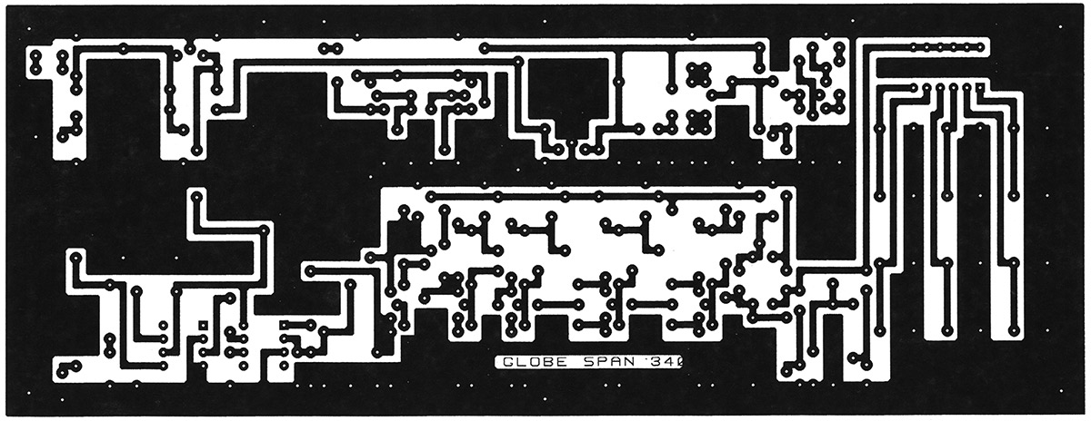
FIGURE 7. Printed Circuit Board Layout.
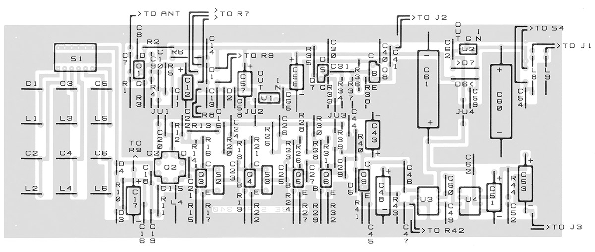
FIGURE 8. Printed Circuit Board Parts Placement Diagram.
If a printed circuit board is used, construction is straightforward. Watch the polarity of diodes and electrolytic capacitors when inserting them into the board. A prototype of the receiver was built on vector board and that version works well. A front panel mounted rotary bandswitch can be substituted for the board mounted dip switch, if desired. More than six bands can be received if some of the inductors are mounted off the board and a switch with more poles is used.
The winding instructions for the toroidal inductors for all the shortwave bands are given in Table 2 and can each be wound in a few minutes. Six of the inductors have to be chosen for the six bands desired. The author chose the coils for 49, 41, 31, 25, 17, and 15 meters. Coils could be designed for the amateur bands or other parts of the shortwave spectrum. Although the radio draws only about 70 mA current from the power supply, using a small DC adapter has resulted in instability. An adapter capable of 500 mA of current is preferable.
| Toroidal Winding Instructions for Inductors L1 through L6 for the 13 International Bands and for Chokes L7 through L9. |
| Band |
Official Frequencies |
Approx. Induct. |
Approximate Toroidal Winding Instructions |
| 120M |
2.3-2.495 MHz |
36 mH |
86 Turns of No. 32 Wire on a T-50-2 Core, or
23 Turns of No. 22 Wire on a FT-50-61 Core |
| 90M |
3.2-3.4 MHz |
19 mH |
62 Turns of No. 28 Wire on a T-50-2 Core, or
17 Turns of No. 20 Wire on a FT-50-61 Core |
| 75M |
3.9-4 MHz |
13 mH |
52 Turns of No. 28 Wire on a T-50-2 Core, or
14 Turns of No. 18 Wire on a FT-50-61 Core |
| 60M |
4.75-5.06 MHz |
8.6 mH |
41 Turns of No. 26 Wire on a T-50-2 Core |
| 49M |
5.95-6.2 MHz |
5.6 mH |
32 Turns of No. 26 Wire on a T-50-2 Core |
| 41M |
7.1-7.3 MHz |
3.9 mH |
26 Turns of No. 24 Wire on a T-50-2 Core |
| 31M |
9.5-9.9 MHz |
2.2 mH |
21 Turns of No. 22 Wire on a T-50-6 Core |
| 25M |
11.65-12.05 MHz |
1.5 mH |
16 Turns of No. 20 Wire on a T-50-6 Core |
| 21M |
13.6-13.8 MHz |
1.0 mH |
14 Turns of No. 18 Wire on a T-50-6 Core |
| 19M |
15.1-15.6 MHz |
0.82 mH |
13 Turns of No. 18 Wire on a T-50-6 Core |
| 16M |
17.55-17.9 MHz |
0.56 mH |
10 Turns of No. 18 Wire on a T-50-6 Core |
| 13M |
21.45-21.85 MHz |
0.33 mH |
9 Turns of No. 18 Wire on a T-50-6 Core |
| 11M |
25.67-26.1 MHz |
0.18 mH |
7 Turns of No. 18 Wire on a T-50-6 Core |
| L7, L8 & L9 |
RF Choke |
47 mH |
29 Turns of No. 22 Wire on a FT-50-61 Core |
TABLE 2.
The circuit board was mounted on a wooden base. The front panel design is shown in Figure 9. Figures 9 and 10 are available at the downloads link at the end of the article. The file names are GlobePanel.bmp and LogDial.bmp. The files are in bitmap format that is readable by most drawing and word processing programs and the Windows accessory programs Wordpad and Paint. Figure 9 was printed full size on legal paper and the paper was laminated. The laminated paper was then glued to particle board and the excess paper was trimed. Holes for the controls were drilled. Poster board edging was placed around the edges of the particle board and laminated paper panel.
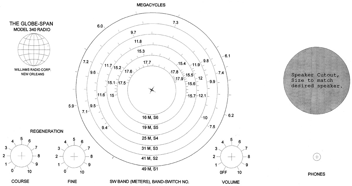
FIGURE 9. Front Panel Layout (shown here at 75%).
An accurate frequency dial can be obtained by tuning the radio to various frequencies and marking the positions on the dial. An RF generator and frequency counter or a marker generator can be used as the signal source.
A log dial that is calibrated in 0 to 100 is the traditional dial for regenerative radios and is not a bad alternative to making a six-section calibrated dial. The word "log" does not mean logarithmic, but refers to providing numbers between 0 and 100 that can be used to "log" station positions in a "log" book. A log dial intended for variable capacitors and one for potentiometers is shown in Figure 10. Since each bandswitch position covers only one international band, one will have a general idea of frequency being received. The position can be logged in order that the same frequency can be found in the future. A third alternative is to use the dial from Figure 9. This dial is attractive, but will not be highly accurate due to variation in varactors, potentiometers, and tuning coils.
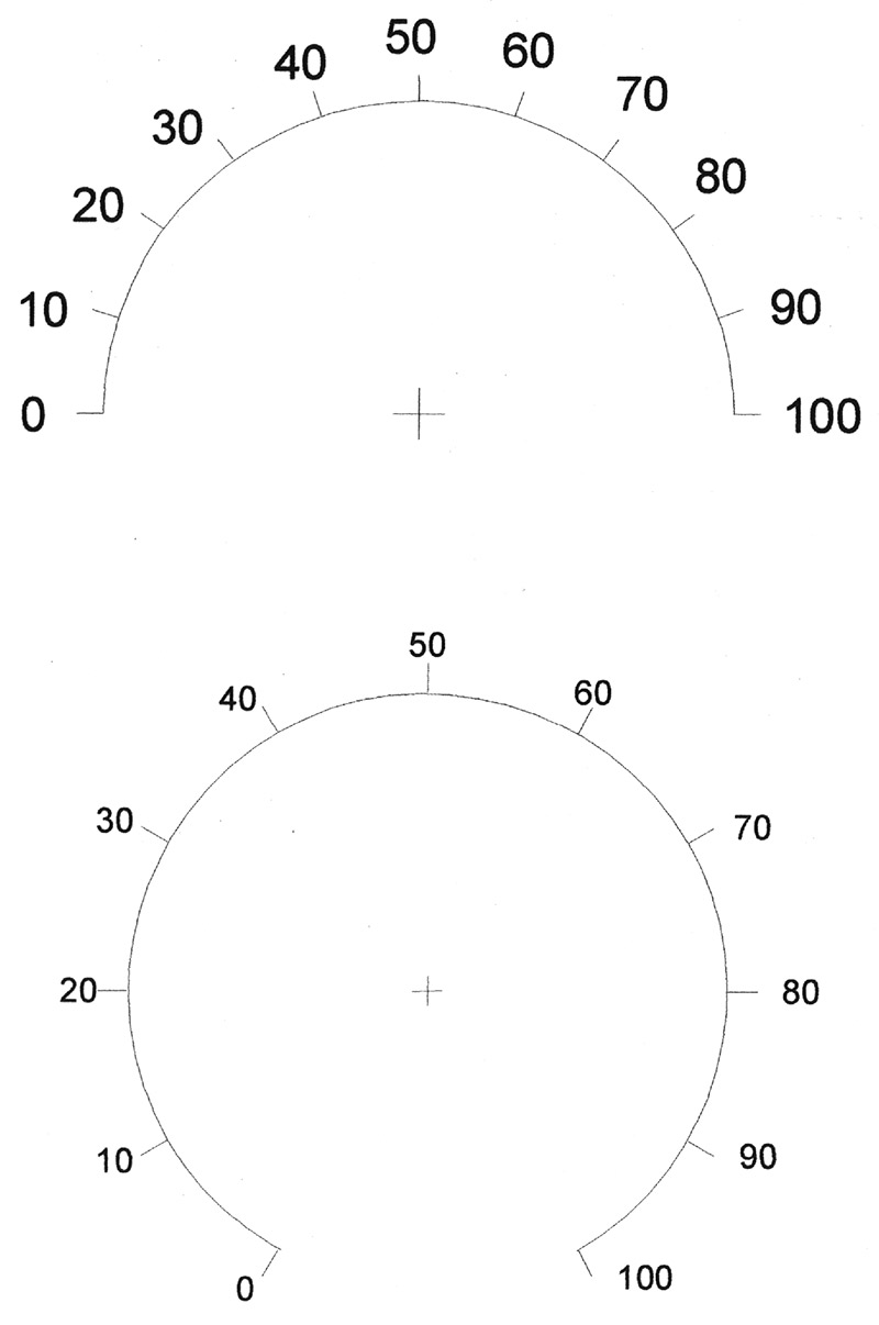
FIGURE 10. A “log” dial provides reference numbers for a received station that can be recorded in a log book so that the station can be located in the future. The two examples here are suitable for variable capacitor tuning (top) and for variable resistor (voltage) tuning (bottom).
Calibration and Operation
The only alignment necessary is adjusting capacitors C1 through C6 so that the radio tunes between the desired frequency limits on each band. The capacitors should have enough range, but if not, a turn can be added or removed from the appropriate toroidal inductor to provide further frequency adjustment. The freedom from tedious calibration procedures is an advantage of this radio over superhet designs. If the Figure 9 tuning dial is being used, C1-C6 can be tuned so that one point near the center of the dial has the correct frequency. The rest of the dial will then indicate approximate frequencies.
A few feet of indoor wire is usually sufficient for an antenna. For many conditions, a short metal whip antenna attached to the wooden base will suffice. An outdoor active antenna is a nice accessory.
The tuning procedure involves setting the regeneration control until the circuit oscillates. When the receiver goes into oscillation, a "thump" will be heard from the speaker. While oscillating, a rushing sound will be heard and when AM stations are passed, a whistle (heterodyne) is heard. The regen control is then backed off until the receiver just stops oscillating. This is the most sensitive setting for the receiver for AM reception. A station is tuned in with the main tuning control and the regeneration control is readjusted for the best performance.
For SSB and code, the regeneration control is adjusted until the receiver is just into oscillation. The receiver then acts as if it had a beat frequency oscillator (BFO) attached. Careful adjustment of the main tuning control and the regeneration control will result in the SSB signal being understandable or the code signal having a pleasant tone.
Although the author owns a number of shortwave receivers from an ancient Collins collossus to a couple of modern Sony digitally-controlled receivers, the GlobeSpan is frequently used. The overall performance of the GlobeSpan falls somewhere between that of a simple superhet and a communications receiver. Considering the simplicity of the regen design, such performance is remarkable. NV
PARTS LIST
SEMICONDUCTORS
D1 — MBD101 hot carrier or 1N34 germanium diode
D2, D5 — 1N914 silicon signal diode
D3, D4 — MV2109 varactor diode
D6, D7 — 1N4001 one-amp silicon diode
Q1, Q7 — 2N5486 junction FET (MPF102 will work)
Q2 — Dual gate MOSFET: MPF121, MPF131, NTE222, or 40673
Q3, Q4, Q5, Q6, Q8, Q9 — 2N3904 general-purpose NPN silicon transistor
U1, U2 — 78L12 voltage regulator, 12 volt
U3 — MC3340P electronic volume control
U4 — LM386 audio power amplifier
RESISTORS
1/4 watt, 5%, carbon, unless otherwise specified.
R1, R10, R33 — 604,000 ohms, metal film
R2 — 180 ohm
R3, R34 — 1,800 ohm, metal film
R4, R5 — 4,700 ohm, metal film
R6 — 15,000 ohm
R7 — 100,000-ohm panel mounted linear potentiometer
R8 — 5,000-ohm panel mounted linear potentiometer
R9 — 10,000-ohm panel mounted audio potentiometer
R11, R17, R22, R27, R32 — 100 ohm, metal film
R12 — 820 ohm
R13, R20, R25, R30, R35, R39 — 1,000 ohm
R14, R18, R23, R28 — 82,000 ohm
R15, R19, R24, R29, R37 — 10,000 ohm
R16, R21, R26, R31, R38 — 1,000 ohm, metal film
R36 — 27,000 ohm
R40 — 10 megohm
R41 — 3,300 ohm
R42, S4 — 50,000-ohm panel mounted linear potentiometer with switch
R43 — 47,000 ohm
R44 — 10 ohm
CAPACITORS
50-volt general-purpose ceramic except where otherwise specified.
C1-C6 — 3.5-20 pF miniature ceramic trimmer
C7, C16, C31, C54, C62 — .001 mF
C8, C11, C13-C15, C20, C22, C24, C26, C28, C30, C44, C55, C58, C47 — .01 mF
C9, C10 — 15 pF silver mica
C12, C17, C43, C57 — 10 mF, 16 volt, electrolytic
C18 — 330 pF silver mica
C19, C42 — 130 pF silver mica
C21, C23, C25, C27, C29 — 10 pF silver mica
C32-C39 — These numbers are not used.
C40, C41, C45, C50, C59 — 0.1 mF
C46 — 0.33 mF polystyrene or Mylar
C48 — 47 mF, 16 volt, electrolytic
C49 — 630 pF
C51 — 100 mF, 16 volt, electrolytic
C52 — 0.047 mF
C53, C56 — 470 mF, 16 volt, electrolytic
C60, C61 — 4,700 mF, 16 volt electrolytic
INDUCTORS
L1-L6 — INDUCTORS that are selected by the builder for the six shortwave bands desired. See Table 2 for winding instructions. Cores depend on the bands chosen. The author used four T-50-6 and two T-50-2 cores.
L7-L9 — 47 mH, self resonate frequency (SRF) greater than 26 MHz (J. W. Miller 9250-473). To hand-wind these inductors, see instructions in Table 2. Three FT-50-61 cores will be required.
MISCELLANEOUS
J1 — 2.1 mm DC power jack (RadioShack 274-1565)
J2 — BNC female chassis mount connector, or other connector suitable for your counter cable.
J3 — 1/8 inch panel mount closed circuit stereo jack (RadioShack 274-246)
BP1, BP2 — Binding post or clips for antenna and ground connection
S1 — Six-pole dip switch
S2, S3 — SPDT miniature slide switch, PC board mountable (RadioShack 275-409)
SPKR — Three-inch speaker RadioShack 40-252, or as desired.
ANT — 30-inch whip antenna Radioshack 270-1401
DC Power Adapter — 15 volts at 500 mA (most unregulated supplies rated at 12 volts actually supply 15 volts and will work). RadioShack RU 11327822.
Miscellaneous — Printed circuit supplies, 6" x 12" x 3/4" wooden base, 7" x 13" x 1/8" particle board front panel, knobs, pointers, bumpers, magnet wire, hook-up wire, and solder.
Downloads
What’s In The Zip?
PCB Patterns
Front Panel Layout