The word ‘optoelectronics’ first came into general use in the 1970s. The word roughly describes the branch of electronics that is concerned with the practical application of light-related optical (opto) phenomena, and with traditional optical devices such as mirrors, prisms, and lenses, and with modern optical devices such as fiber optic cables, LEDs, and lasers.
Most Nuts & Volts readers will have few problems in understanding the purely electronic aspects of optoelectronics, but probably have very limited knowledge of its optical parts. This new four-part series aims to help remedy the latter situation by giving fairly concise descriptions of vital optoelectronics-related ‘opto’ subjects.
This opening episode deals with the basic nature and behavior of light, and with mirrors. Part 2 will deal with prisms and lenses. The final two episodes will deal with fiber optic communication and with LED and laser operating principles.
LIGHT
Light is a form of energy and is transported by electromagnetic radiation. It has an apparent dualistic nature that enables it to be regarded as both a wave phenomenon and as a flux-like flow of sub-atomic particles known as photons, which are released as a consequence of shifts in the energy levels of atoms, such as those caused by heating or various other disturbences.
All active (moving) photons are endowed with parameters such as frequency (f), velocity (v), free-space wavelength (λ), and mass, and thus represent a finite unit of energy (e). In pure physics, the photon’s energy, in joules per second, is usually defined by the formula
e = h x f
in which h is Planck’s constant (= 6.626 x 10⁻³⁴ J s).
In optoelectronics, it is more useful to define the energy in terms of electron-volt (eV) units, and to relate it to the photon’s wavelength (λ) in nanometers (nm) rather than its frequency. In this case, the basic formula transforms into the easily remembered form
eV = 1240/λ
Thus, an LED that generates a red output at a wavelength of 645nm has a bandgap energy value of 1.92 eV. The energy value of an individual photon depends on its actual wavelength, but is very small; an ordinary green LED, for example, generates an output flux flow of about 2,500 million photons per microsecond at a mean light output power level of a mere 1mW.
Figure 1 shows a simple conceptual diagram that illustrates some basic features of light when radiated from a small point source.
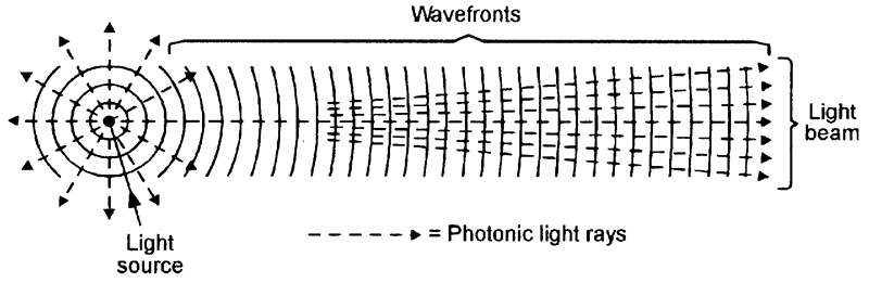
FIGURE 1. Conceptual diagram illustrating some basic features of radiated light.
The light flux (which contains vast numbers of photons) is effectively radiated in the form of a continuous series of spherical photonic waves that become progressively more planar (less sharply curved) as they move further from the source.
The photons move outwards, perpendicular to the wave fronts; a photonic light ray traces the mean path of a photon, a photonic light beam depicts the paths of a collection of rays. A light beam is angular when close to the light source, but becomes progressively more parallel as the distance from the source increases.
In optoelectronics, the term ‘light’ relates to the entire visible light (400nm to 700nm) part of the electromagnetic spectrum, plus most of its invisible infrared (IR) and ultra-violet (UV) ranges, i.e., to the spectrum’s 10nm to 100µm section. Figure 2 shows details of the full electromagnetic spectrum, and Figure 3 shows the so-called ‘visible’ part of the spectrum. All wavelengths are marked in decade multiples and submultiples of the meter.
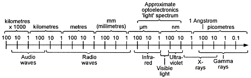
FIGURE 2. The full electromagnetic spectrum (wavelengths are given in decade multiples and submultiples of the meter).
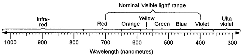
FIGURE 3. The visible light part of the spectrum (wavelengths are in nanometers).
The sun is the most powerful light generator in our solar system. It generates and radiates light energy as a byproduct of its continuously-active nuclear fusion process; 60% of its radiant energy lays in the IR range. Only 0.0005% of the sun’s radiated energy is (after travelling a mean distance of 93 million miles through space in 8 minutes 20 seconds) received by planet Earth, and one third of this reflects directly back into space. The energy contained in the remaining flux delivers a mean power of 4KW per square meter per day to the earth’s surface, and acts as the engine for our planet’s weather systems and (as a consequence of the results of photosynthesis, etc.) sustains all life on our planet.
Light travels through empty space at a velocity of 186,282 miles (299,792 kilometers) per second. Light’s velocity was first estimated with reasonable precision by the Danish astronomer Ole Roemer in about 1690, after he observed unexpected variations in the actual and predicted times of the eclipse of Saturn’s moons.
The velocity of light through the earth’s atmosphere (which is 0.03 percent slower than through empty space) was first measured with reasonable precision (within five percent) by the French amateur scientist Armand Fizeau in Paris in 1849.
Fizeau used an opto-mechanical stroboscopic technique to measure the time (about 57µS) that a beam of light took to cover a two-way, 17km journey and, from the results, estimated the speed of light at 313,300 kilometers per second.
THE VISIBILITY OF LIGHT
A stream of light (photons) racing through empty space can be regarded as a stream of latent energy, and is quite invisible; it only becomes visible when its flux strikes an absorptive material and releases some or all of its latent energy. These effects can be observed by looking up at the moon on a clear night; parts of its surface are illuminated because they are absorbing energy from the rays of the sun, which is out of sight below earth’s horizon; the areas of space through which the sunlight is travelling appear completely dark.
If you go out into the open air on a bright summer’s day, you will be bombarded by a stream of solar-generated IR, UV, and visible light rays that will produce three distinct types of physiological effects on you. The IR rays will produce a sense of warmth wherever they strike exposed areas of your skin, and the UV rays will slowly start to change your skin’s pigmentation in those exposed areas, eventually giving them a deep tan. The visible light rays from the sun span the full color spectrum. When they strike an object that you can see, the object’s visual coloring is dictated by the object’s spectral characteristics.
If the object that is exposed to the sun’s light absorbs all of the spectrum’s light energy, the object appears black. If it absorbs only part of the available energy and reflects the rest, it will appear white if it reflects light equally across the entire spectrum, or red if it reflects mainly the red part of the spectrum, or green if it reflects mainly the green part of the spectrum, and so on. The apparent colors have degrees of purity that depend on the width of the reflected part of the spectrum.
Note that human eyes do not have a linear spectral response (just as our ears do not have a linear aural response) and the response varies between individuals. The graph of Figure 4 shows the spectral response of typical human eyes, which are 10 times more sensitive to yellow-green (560nm wavelength) than they are to mid-blue (470nm) or mid-red (660nm).
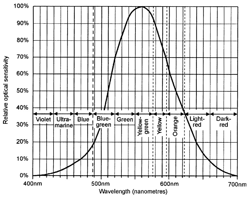
FIGURE 4. Standardized relative spectral response of the human eye.
You can observe these effects by looking at a stained glass window (from within a building) when the window is brightly illuminated by the sun; the window’s glass segments all have roughly similar values of translucence, but the green segments seem far brighter than the mid-red or blue ones. The next section of this article gives more details on this subject.
LIGHT UNITS
When dealing with light and optoelectronic components such as LEDs and lasers, etc., the units most often used in data sheets are those relating to the light’s wavelength and spectral bandwidth, and to the intensity and power levels of its flux. Light wavelength is a measure of the light’s color; visible-light wavelengths fall within the range 400nm to 700nm; UV-light has a wavelength below 400nm; IR-light has a wavelength above 700nm.
The color purity of a light is defined by its spectral bandwidth, which is measured between the points where the radiated power falls to half of its peak value. True white light contains all the colors of the 400nm to 700nm spectrum; it thus has a bandwidth of at least 300nm and is known as chromatic (multi-toned) light.
Red LEDs (operating at about 650nm) have typical spectral bandwidths in the range 15nm to 50nm and are thus also chromatic, since their light outputs span various shades of red.
Laser-generated light usually has an exceptionally narrow bandwidth (often less than 0.01nm), and is known as mono-chromatic (one-toned or pure-toned) or (if all of its emitted photons are in phase) coherent light.
Dealing next with the light units concerned with values of light intensity and power, it is important to note that — since human sight does not have a linear spectral response — these values may be expressed in two different types of unit. Conventionally, photometric units are used if they relate to the physiological (apparent) values of visible light sensed by humans, and radiometric units are used if they relate to genuine (true) values of visible or IR or UV light. The following four basic types of unit (each of which has both photometric and radiometric notations) are widely used in optoelectronics.
TOTAL RADIATED FLUX POWER
Light is radiated energy; the total power of the flux flowing from a light source is measured in watts in radiometric notation, or in lumens in photometric notation. The photometric quantities are related to the corresponding radiometric ones by the internationally-recognized standard ‘human eyeball response’ photopic conversion graph shown in Figure 5, which shows that one watt of light power is equal to 680 photometric lumens at a wavelength of 555nm (yellow-green), or roughly 82 lumens at 475nm (mid-blue), or 65 lumens at 660nm (mid-red), and so on.
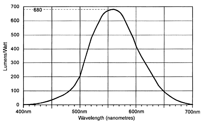
FIGURE 5. Standard ‘human eyeball response’ photopic conversion graph showing the photometric lumens to radiometric watts relationship.
FLUX DENSITY
In most practical optoelectronic applications, only a small fraction of a light source’s total radiated power falls on a targeted light receptor such as a photocell or an eye’s retina and, in such cases, the most relevant parameter is the light’s flux density (brightness) at the actual target point.
In radiometric notation, this parameter is known as the light’s irradiance value and is measured in watts per square meter (W/m2). In photometric notation, the parameter is known as illuminance and is measured in lumens per square meter (lm/m2) or ‘lux.’ The lumen/watt relationship is the same as that shown in Figure 5.
ANGULAR FLUX INTENSITY
Man-made light generators such as LEDs and filament lamps act like crude ‘point’ light sources, but produce directional outputs, i.e., most of their available flux is concentrated into a cone of radiation. To specify flux intensity in such cases, a standard three-dimensional angular unit known as a steradian (symbol sr) is used; in radiometric measurements, angular flux intensity is known as radiant intensity and is specified in units of watts per steradian (W/sr); in photometric measurements, angular flux intensity is known as luminous intensity and is specified in units of candela, in which one candela equals one lumen per steradian (lm/sr).
Figure 6 shows a conceptual diagram that illustrates the basic features of a steradian unit.
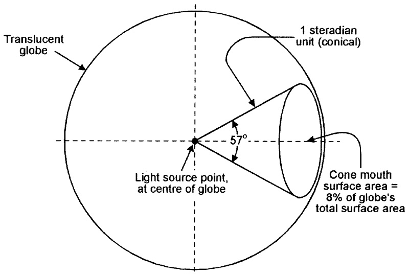
FIGURE 6. Conceptual diagram illustrating the basic features of a steradian unit.
Imagine here that a point source of light is set at the center of a translucent globe. From the point source, form a 57º cone that reaches out to the surface of the globe. This cone is a three-dimensional angular unit known as a steradian; the surface area of its mouth encompasses approximately 8% of the globe’s total surface area.
RADIATED FLUX BRIGHTNESS
The brightness of a light source is proportional to both the radiated flux density and the radiating surface area of the light source. In radiometric notation, this parameter is known as the light source’s radiance value and is measured in watts per steradian per square meter (W/sr x m2) of radiating surface area. In photometric notation, the parameter is known as luminance and is measured in lumens per steradian per square meter (lm/sr x m2) or candela per square meter (cd/m2).
LIGHT-BEAM MANIPULATORS
Visible and IR light beams can readily be reflected, bent, or manipulated in various other geometric ways with the aid of simple optical devices such as mirrors, retroreflectors, prisms, or lenses. This next section — and the whole of our next episode — describes the basic operating principles and optoelectronic applications of such devices.
MIRRORS
The simplest mirror is the ordinary flat totally-reflective silvered-back glass type. If a narrow beam of light is aimed through the glass and onto the reflective (rear) surface of such a mirror, the reflected beam always obeys the basic law of reflection, which is illustrated in Figure 7, and states that the angle of incidence (the angle between the arriving ray and an imaginary line drawn perpendicular to the mirror’s surface) and the angle of reflection (the angle between the reflected ray and the imaginary perpendicular line) are exactly equal.
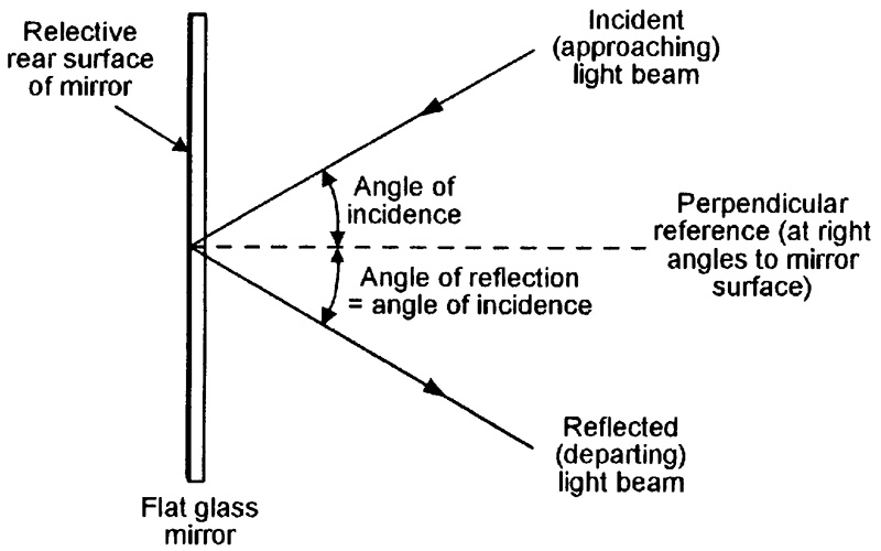
FIGURE 7. Diagram illustrating the basic law of reflection that applies to a flat mirror.
Figure 8 shows two simple ways of using a mirror in optoelectronic security applications. In Figure 8(a), the mirror is used in a corridor protection system, to link a coded Tx IR light beam into an adjacent Rx unit, which activates an alarm if the beam is interrupted.
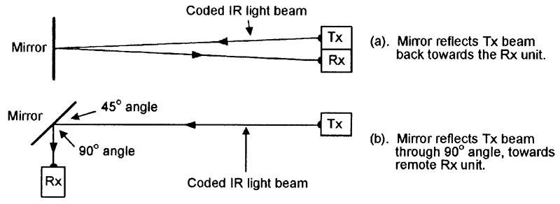
FIGURE 8. Two simple ways of using mirrors in optoelectronic security applications.
In Figure 8(b), the mirror is angled at 45º and projects the Tx beam around a 90º corner and on to a remotely-placed Rx unit; this system can be used to protect an L-shaped corridor or two adjoining outside walls of a building, and is aligned by aiming the Tx beam directly at the mirror’s Rx image.
Note that the image reflected by a simple mirror is reversed, left-to-right, as shown in Figure 9.
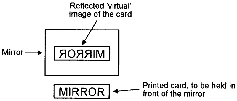
FIGURE 9. The image reflected by a simple mirror is reversed, left-to-right.
If you take Figure 9 and hold it in front of a mirror, you will see that all of its text is reversed in the reflected image, which is thus known as a ‘virtual’ (rather than real) image. While you are standing in front of the mirror, scratch your right ear; you will see that your virtual image is scratching its left ear.
If a mirror’s reflection is viewed in a second mirror, the image that appears in the second mirror becomes real, rather than virtual. Try standing sideways in front of a large mirror, with a small mirror in your left hand; use the small hand mirror to view your image in the large mirror, and scratch your right ear; note that your image also scratches its right ear, but that if you look at your virtual images directly in either mirror, it is the left ear that is being scratched.
One of the most common applications of the above two-mirror technique is in simple periscopes, as illustrated in Figure 10. Figure 10(a) shows the basic construction of a conventional ‘view-above’ type of periscope. Here, the light from the scene that is being viewed strikes the upper mirror, is reflected downwards at an angle of 90º, and strikes the face of the lower mirror, which bends the light through another 90º, where it can be viewed by the eye of the observer. The resulting image is real, rather than virtual, and is seen from a perspective above the viewer’s eye level.
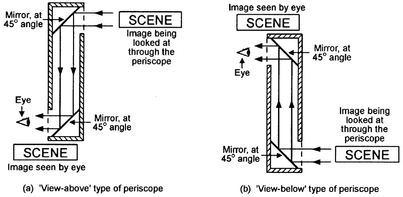
FIGURE 10. A periscope presents a genuine (rather than ‘virtual’) image of a viewed scene.
The ‘view-above’ periscope of Figure 10(a) can be used as a ‘view-below’ type by turning it upside-down, as in Figure 10(b). View-below periscopes are often used in the movie and TV industries to obtain ground-level shots of small animals or of miniature (model) towns or battle scenes, etc., for use in various films/videos.
RETROREFLECTORS
A retroreflector is a passive device that automatically reflects a light’s radiation back towards its source, irrespective of the light’s precise angle of incidence. Devices of this type are widely used in reflective optoelectronic light-beam security alarms and barrier control systems, and do not have to be precisely aligned with the light-beam source.
Figure 11 shows a way of using two small mirrors (or mirror tiles) to make a device known as a cube corner retroreflector.
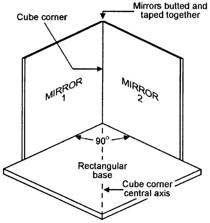
FIGURE 11. Basic construction of a simple ‘cube corner’ retroreflector.
The two mirrors are simply butted and taped together and set at an angle of 90º degrees by pressing them against the edges of a rectangular base (such as a soft-cover book).
If a light beam (or image) is aimed into the cube corner of this device from any point that is at right angles to the cube’s vertical plane, and anywhere within ±35º of its central corner axis on the horizontal plane, the device automatically reflects the light (or image) back towards its source point. Figure 12 illustrates the unit’s operating principle.
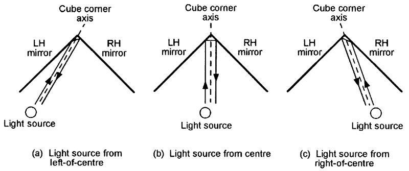
FIGURE 12. Diagram illustrating the functional operation of the cube corner retroreflector.
In Figure 12(a), the light beam is projected from a left-of-center source towards the retroreflector’s corner, hits the LH mirror at an incident angle of (say) 75º, is reflected off again at 75º, hits the RH mirror at an incident angle of 15º, and is reflected off again at an angle of 15º, and heads back towards the source on a parallel path.
The light beam’s total angular change is equal to the sum of the two incident and two reflection angles, and inevitably equals 180º. This same basic action is obtained in Figures 12(b) and (c), except that different incident and reflection angles are involved and that the Figure 12(c) illustration shows the beam bouncing from the RH mirror on to the LH one.
Note in Figure 12 that an imaginary line drawn centrally between the transmitted and returning parallel beams always hits the cube corner, and that the two beams thus lay symmetrically about this line. This action enables the cube corner retroreflector to produce some unusual visual effects when viewed in frontal elevation, as illustrated in Figure 13.
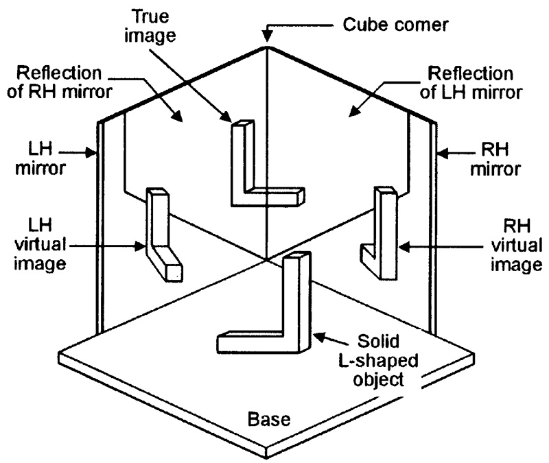
FIGURE 13. When viewed in frontal elevation, this retroreflector produces three images of an object.
In Figure 13, a three-dimensional, solid L-shaped model is turned around so that it is facing the retroreflector and is placed in front of its cube corner. Note that the LH mirror reflects the RH mirror, and vice versa, producing a ‘mirror cube’ reflection. The retroreflector produces virtual images of the object in both the LH and RH mirrors, and produces a true image of the object in the mirror cube.
The cube corner unit gives only one-dimensional (horizontal plane) retroreflection. An alternative design is the trihedral unit, which gives two-dimensional (vertical and horizontal planes) retroreflection of light beams.
Figure 14 shows the basic construction of this unit, which uses three diamond-shaped mirrors set at 120º to each other; the unit’s action is such that a light beam entering its front is reflected through 180º in two dimensions by the mirror surfaces and then returns towards the source point on a parallel path.
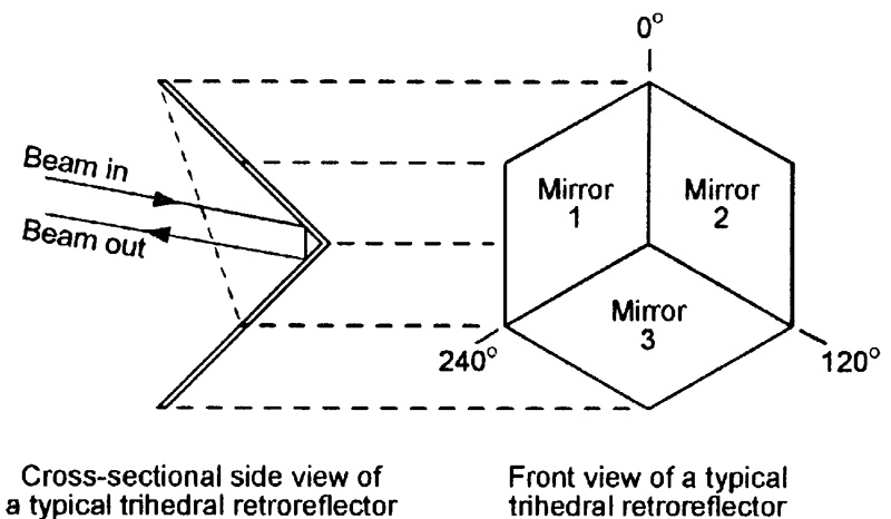
FIGURE 14. Basic construction of a trihedral retroreflector.
Often, hundreds of miniature retroreflectors of this basic type are used in road-side signs, making them glow brilliantly in the headlights of passing vehicles.
Our next episode of this series will describe the action and applications of prisms and lenses. NV