The first two episodes of this mini-series described the basic nature and behavior of light and light-beam manipulators such as mirrors, prisms, and lenses, with particular regard to their use in modern optoelectronic systems.
This part continues the ‘light-beam manipulator’ theme by describing the basic nature and behavior of modern fiber optic cables and systems.
FIBER OPTICS
INTRODUCTION
A fiber optic cable can, in very simple terms, be regarded as a hair-thin flexible light pipe or optical waveguide that can efficiently carry modulated or unmodulated light signals from one point to another (even if the journey involves bends and loops) with complete immunity from electromagnetic interference.
In most practical applications, the cable must be linked to the light source and destination points via special connectors, to minimize signal losses.
Figure 1 shows the basic elements of a simple one-channel, one-way fiber optic communication system, in which the output of the optogenerator LED is pulse-modulated and is coupled to the input of optosensor Q1 and its pulse-detecting unit via a length of sheathed fiber optic cable.
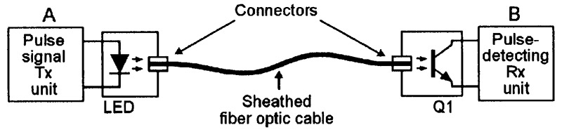
FIGURE 1. Simple single-channel one-way fiber optic communication system.
The Figure 1 circuit can send data from point A to point B, but not the other way around. Figure 2 shows a two-way (bidirectional) version of the above circuit. Here, signals can be sent from A to B via Tx unit 1, cable 1, and Rx unit 1, and from point B to point A via Tx unit 2, cable 2, and Rx unit 2. In practice, special two-core ‘duplex’ fiber optic cables are available for use in this type of application.
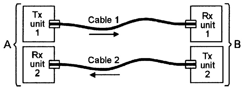
FIGURE 2. Simple single-channel two-way fiber optic communication system.
The Figure 1 and 2 circuits are designed for use in applications in which each fiber optic cable carries only a single data channel. If multi-channel operation is needed, the channels can be electronically multiplexed, or each channel can be superimposed in a high-frequency carrier wave in the manner of a normal radio or TV channel.
When the commercial possibilities of fiber optic cables were first postulated in the early 1960s, there was much speculation regarding the probable performance capabilities of such cables.
Visible light has, for example, a frequency spectrum ranging from 430,000MHz (700nm wavelength) to 750,000MHz (400nm wavelength), and it was presumed that fiber optic cables would have bandwidths that would easily cover this 320,000MHz spectrum, thus enabling them to handle up to 64,000 5MHz data channels.
In practice, modern fiber optic cables fall well short of this imagined ideal; many have real-life bandwidths of only a few hundred MHz, and can handle only a few dozen 5MHz data channels.
In spite of their limitations, fiber optic communication systems outperform conventional wire-connected systems in many important respects. They are immune to electromagnetic interference, are electrically fully isolated, are low in weight, offer high security, and (unlike copper wires) are made from a cheap and very abundant raw material (silica).
FIBER OPTIC PRINCIPLES
An optical fiber is a wire-like strand of high-purity glass or plastic in which the refractive index of the outer layer is lower than that of the inner core, thus endowing the fiber with the optical phenomenon of total internal reflection (as described in Part 2 of this series).
Figure 3 illustrates some elementary fiber optic operating principles and helps explain some basic fiber optic jargon. The main (a) part of the diagram shows a simple glass rod or ‘light pipe’ in which the glass has a refractive index of 1.5; light rays travel through this glass at a speed of 200 meters/µS.
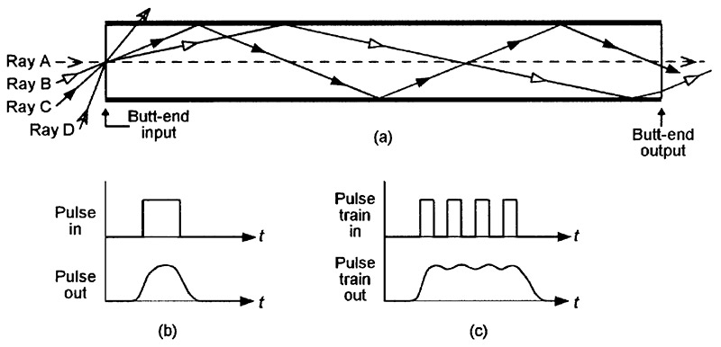
FIGURE 3. Diagram illustrating basic ‘step index’ fiber optic operating principles.
Imagine in Figure 3 that a series of light-beam pulses are fed into the butt-end input of the glass rod via a focusing lens. The beam is made up of a vast number of photonic rays, which enter the butt-end input at a variety of angles of incidence. The diagram depicts the paths of four such rays, which travel in the following individual ways.
Ray A strikes the butt-end input of the glass rod at an angle of incidence of zero degrees, passes cleanly through the glass rod via the shortest possible route, and emerges from the rod’s butt-end output after traveling through the rod at a mean speed of 200 meters/µS.
Ray B strikes the butt-end input at a moderately sharp angle of incidence, is refracted to an angle of 12° on entering the glass and, after traveling a fairly short distance, strikes the rod’s upper glass-to-air boundary, where (because it arrives at a fairly shallow angle) it is subjected to the phenomena of total internal reflection (see Part 2 of this series), which reflects the ray downwards at an identical angle until it strikes the rod’s lower glass-to-air boundary, from which it is reflected upwards again, and so on as the ray propagates its way along the rod until it eventually leaves its butt-end output.
The ray thus follows the repeatedly-reflected zig-zag course shown in the diagram; this beam travels a greater distance than ray A in its journey through the glass rod, actually traveling through it at a mean horizontal speed of 195 meters/µS.
Ray C, on entering the rod, is refracted to an angle of 22° on entering the glass and then propagates its way along the tube in the same basic way as ray B, but does so at sharper reflective angles and thus takes even longer than ray B to complete its journey through the glass rod, actually traveling through it at a mean speed of 185 meters/µS.
Ray D strikes the butt-end input at a very sharp angle of incidence, is refracted to an angle of about 60° on entering the glass and, after traveling a short distance, strikes the rod’s upper glass-to-air boundary, where (because it arrives at an angle greater than the critical angle of the boundary) it simply passes through the boundary and is dissipated into the air. This ray thus fails to propagate along the glass rod.
Note that Figure 3 depicts the fiber optic rod’s operation in a simplified two-dimensional style, in which the rays simply bounce off of the internal top and bottom faces of the rod. In reality, rays travel three-dimensionally, bouncing off of the rod’s top, side, and bottom faces, and thus tend to spin or skew as they travel along the rod.
FIBER OPTIC JARGON
Various ‘jargon’ words and phrases are widely used in fiber optics and have meanings that can be explained with the aid of Figure 3, as follows.
Step Index.
Fiber optic cable operation depends on the total internal reflection phenomenon that can occur at the points where a transparent material meets a material or substance with a refractive index lower than its own. In the Figure 3 example, the glass rod has a refractive index of 1.5, and the surrounding air has a refractive index of 1.0, and reflection can occur at the precise point where the ray meets the abrupt or step reduction of the refractive index. Cables of this type are called step index fiber optic cables. Graded index cables are also available, and are described later in this article.
Maximum Acceptance Angle and Numerical Aperture.
Light rays will only propagate through a fiber optic cable if the input ray applied to the cable’s butt-end input falls within a certain angular range.
In Figure 3, for example, rays A (arrival angle = 0°), B (24°), and C (45°) all propagate, but ray D (75°) does not propagate. The maximum input angle at which propagation will occur is called the cable’s maximum acceptance angle, and is denoted by the symbol αM. This basic parameter is often expressed in sine form, in which case, it is called the cable’s numerical aperture (NA), and equals sin αM. Thus, a cable with a maximum acceptance angle of 32° has a numerical aperture of 0.53.
Operating mode.
In Figure 3, light rays can propagate along the glass rod at a variety of angles or ‘operating modes.’ Rays that propagate at steep reflective angles travel in high-order mode, and ones that propagate at shallow angles travel in low-order mode. Since the rays can travel in a variety of modes in this particular fiber optic rod, it is called a multi-mode or MM device. Some fiber optic cables can operate in only a single mode, and are called single mode (SM) or monomode devices.
Modal Dispersion.
When light rays propagate through a step index multi-mode fiber optic cable or rod, their speed of linear travel depends on their angular operating mode. High-order mode rays travel at lower linear speeds than low-order ones. In the Figure 3 diagram, for example, ray A travels at a linear speed of 200 meters/µS and takes 5nS to travel one-meter; the slowest (highest-order) ray that can propagate through this particular rod travels at 141 meters/µS and takes 7.1nS to travel one-meter.
Consequently, if a very fast sharp-edged light pulse is fed to the input of the Figure 3 fiber optic rod, the individual photonic rays representing its leading or trailing edge at the rod’s output are spread over a 2.1nS time spread in a one-meter rod, or 21nS in a 10-meter rod, and so on.
This ‘spreading’ is called modal dispersion and produces a degraded (blurred) output pulse, as shown in Figure 3(b). Similarly, if a train of ultra-fast pulses are fed through the rod, modal dispersion may degrade them into the form of a single pulse, as shown in Figure 3(c).
Modal dispersion is the major factor that limits the maximum pulse-operating rates (frequencies) of fiber optic cable, and is determined both by the design and the length of the cable. Cables with low modal dispersion figures offer higher maximum pulse operating rates than ones with high modal dispersion figures.
Material Dispersion.
The speed at which light travels through a fiber optic material depends upon the material’s refractive index, and this varies with the light’s wavelength. All real-life light sources have finite spectral bandwidths, and their different component wavelengths thus travel through the material at different speeds; such light thus undergoes spectral dispersion (spreading) as it travels through the fiber.
This phenomenon is known as material dispersion, and — like modal dispersion — limits the maximum pulse-operating rates of fiber optic cable. Its degrading effects are directly proportional to the light source’s spectral bandwidth, but are normally small compared to those caused by modal dispersion. Material dispersion can typically be reduced by a factor of about 200 by using a laser diode, rather than a normal LED, as the light source that feeds signals into the fiber optic cable.
Attenuation.
When light passes through any translucent glass or plastic material, its power is inevitably attenuated in the process. The amount of attenuation is directly proportional to the thickness (or length) of the material, and is measured in terms of dB/meter or dB/km.
The high-quality glass used in spectacle lenses has a typical attenuation value of 6dB/meter (6,000 dB/km). By contrast, the ultra-pure silica (silicon dioxide) glass used in glass fiber optic cables has a typical attenuation value of less than 0.0013dB/meter (1.3dB/km) when used under optimum conditions.
Four basic mechanisms are primary causes of light attenuation in glass. Three of these (electron absorption, Rayleigh scattering, and material absorption) are intrinsic absorption mechanisms inherent in the basic nature of glass; the fourth mechanism (impurity absorption) is an extrinsic absorption mechanism caused by contamination (impurity) within the manufactured glass.
In ordinary glass, the extrinsic (impurity) absorption is the dominant mechanism in the basic attenuation process. In modern fiber optic cables, the impurities in the silica glass are reduced to the lowest commercially-viable levels, and this results in the type of attenuation graph shown in Figure 6 which, in turn, is derived by combining the intrinsic and extrinsic absorption graphs shown in Figures 4 and 5. Note that these particular graphs are based on typical cable of the late 1980s to early 1990s era, and that most modern cables give attenuation figures that are somewhat lower than those shown.
The Figure 4 graph shows the typical attenuation that occurs as a result of the intrinsic absorption mechanisms inherent in the basic nature of silica glass. Here, electron absorption occurs when photons are absorbed by individual atoms in the silica glass, raising the atom’s electrons to a high energy (excited) state in the process. Electron absorption causes heavy ultra-violet absorption that peaks at 140nm, but extends well beyond 400nm wavelengths.
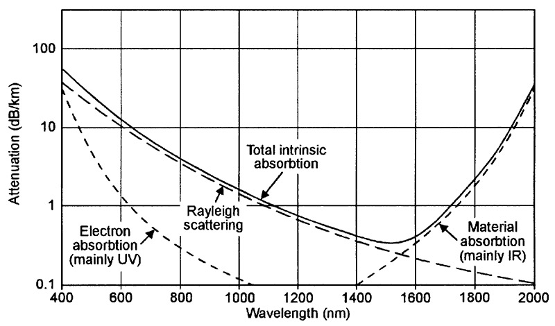
FIGURE 4. Graph showing typical attenuation due to intrinsic optical absorption in high-grade silica fiber optic glass cables of the late 1980s to early 1990s era.
The Rayleigh scattering shown in Figure 4 occurs when photons meet molecule-sized density irregularities in the glass and undergo shifts in their refraction angles. The consequent attenuation effects are severe when the photon’s wavelength is similar to the dimension of the irregularity, but decline steadily as wavelength increases above 400nm.
The material absorption shown in Figure 4 occurs when photon energy is absorbed by the atomic/molecular bonds associated with the basic glass material, and causes heavy attenuation of infrared at wavelengths greater than 2000nm. The net result of the effects of the three intrinsic absorption mechanisms is that the optical attenuation of the glass is high (70dB/km) at 400nm, falls smoothly to a minimum value of about 0.4dB/km at 1500nm, and then rises rapidly again (because of material absorption) at longer wavelengths.
The Figure 5 graph shows the basic form of the attenuation that occurs as a result of extrinsic absorption mechanisms in most high-grade normal-quality silica fiber optic glass. These losses are caused primarily by the presence of hydroxyl (OH) ions in the glass, which result in three large peaks of absorption within the 400nm to 2000nm spectrum. The largest peak occurs at 1370nm, and the other two occur at 950nm and 725nm; a very minor additional peak occurs at 1230nm.
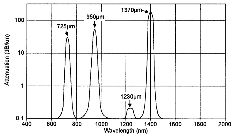
FIGURE 5. Graph showing typical attenuation due to extrinsic optical absorption in high-grade silica fiber optic glass cables of the late 1980s to early 1990s era.
The Figure 6 graph shows the typical attenuation that occurs as a result of all intrinsic and extrinsic absorption mechanisms in high-grade normal-quality silica fiber optic glass.
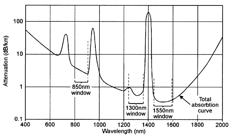
FIGURE 6. Graph showing typical attenuation due to all forms of optical absorbtion in high-grade silica fiber optic glass cables of the late 1980s to early 1990s era.
Important points to note from this particular graph are that attenuation is very high (greater than 10dB/km) over most of the visible-light (400nm to 700nm) spectrum and in various other areas, and that there are three ‘window’ areas in the infrared range (at 850nm, 1300nm, and 1550nm) at which attenuation figures attain local ‘low’ values. Practical glass fiber optic communication systems are nearly always operated within one or the other of these ‘window’ ranges.
Polymer Cable.
The most widely used type of fiber optic cable is made from silica glass and can only be correctly cut with a special tool. This type of cable is meant for use with IR light, primarily in medium- to long-haul (greater than 250 meters) communication and data-transfer systems. There is, however, an alternative and cheaper type of fiber optic cable; it is made from plastic polymer and can easily be cleanly cut with a sharp blade, and is best suited to use with visible red (rather than IR) light, in very-short-haul (up to 50 meters maximum) applications.
Figure 7 shows the typical attenuation graph of a modern polymer fiber optic cable.
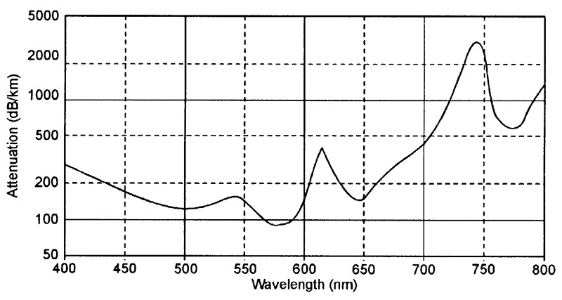
FIGURE 7. Graph showing typical attenuation due to all forms of optical absorption in modern plastic polymer fiber optic cable.
This particular cable gives a mean attenuation of about 200 dB/km (0.2dB/meter) when averaged over the full visible light spectrum, but about 1500 dB/km (1.5dB/meter) when used in the low infrared ranges.
PRACTICAL FIBER OPTIC CABLE TYPES
The simple glass type of fiber optic rod or cable shown in Figure 3 is too crude to be of real practical value, since its internally-reflective glass-to-air junction is highly susceptible to external damage from scratches and contamination, and the very large differences between the refractive index values of its two media (about 1.5 for glass, 1.0 for air) give excessively large modal dispersion values.
All practical, modern, fiber optic cables are designed to give low values of modal dispersion, and use either a multi-mode or single-mode step-index form of construction, or a graded-index (GRIN) form of construction, as shown in Figures 8 to 10, which also show the basic refractive index (n) profiles and typical dimensions of their ‘glass type’ fibers.
Each of these fibers has a solid core that is surrounded by a solid cladding with a refractive index value lower than that of the core; this cladding makes the cable’s modal dispersion value immune to the effects of external surface scratches, etc. The outer core is further enclosed in an opaque primary outer sheath that provides further physical protection and immunity to optical interference.
Descriptions of the three basic cable types are given below; when reading these descriptions, remember that a human hair has a typical thickness of about 50µm, and note that fiber optic cable basic dimensions are conventionally notated in an ‘a/b/c’ or ‘a/b’ form, in which ‘a’ is the outside diameter of the fiber core in µm, ‘b’ is the outside diameter of the fiber cladding in µm, and ‘c’ is the outside diameter of the cable’s primary outer sheath in µm. Thus, a 50/125/250µm cable uses a 50/125µm fiber that is protected by a 250µm-diameter primary sheath.
MULTI-MODE STEP-INDEX CABLES
Figure 8 shows basic details of this type of fiber optic cable, in which a relatively thick core (typically 50µm or 62.5µm in glass fibers) is covered by a layer of cladding with a refractive index value that is only a few percent lower than that of the core, thus giving the fiber’s butt-end input a fairly narrow (typically 11° to 24° maximum) acceptance angle and thus endowing the fiber with fairly low values of modal dispersion.
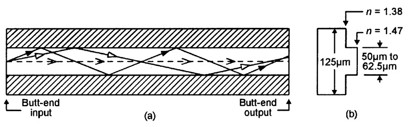
FIGURE 8. Basic details (a), plus refractive index profile and typical dimensions (b), of the glass fiber used in a modern multi-mode step-index fiber optic cable.
These characteristics and dimensions make it easy to couple optical signals into and out of this type of cable. The most popular ‘glass’ versions of this cable have basic fiber dimensions of 50/125µm or 62.5/125µm. Typical bandwidth/length product values vary from 1MHz/km for plastic cables to 33MHz/km for glass types; these cables are thus used mainly in short- to medium-haul low-data-rate applications.
SINGLE-MODE STEP-INDEX CABLES
Figure 9 shows basic details of a typical single-mode step-index fiber optic cable, in which a very thin (typically 5 to 8µm) glass core is covered by a relatively thick layer of cladding with a refractive index value that is only slightly lower than that of the core, thus giving the fiber’s butt-end input a very narrow (less than 6° maximum) acceptance angle and endowing the fiber with a very low modal dispersion value.
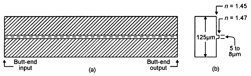
FIGURE 9. Basic details (a), plus refractive index profile and typical dimensions (b), of the glass fiber used in a modern single-mode step-index fiber optic cable.
These characteristics and dimensions make it difficult to couple optical signals into and out of the cable, which requires great precision in cutting and coupling. Nevertheless, the great bandwidth/length product values of this type of cable (usually between 1GHz/km and 10GHz/km) make it the most widely used type in long-haul high-data-rate applications.
GRADED-INDEX (GRIN) CABLES
Figure 10 shows basic details of a ‘GRIN’ type of fiber optic cable. Here, the core has a refractive index value of about 1.47 along its central axis, but the value gradually diminishes (in ‘graded’ form) as the distance away from the central axis increases, until it falls to a minimum value of (say) 1.38.
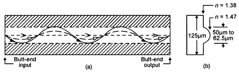
FIGURE 10. Basic details (a), plus refractive index profile and typical dimensions (b), of the glass fiber used in a modern graded-index (GRIN) fiber optic cable.
Photonic rays that arrive at the cable’s butt-end input at fairly sharp angles of incidence are progressively refracted downwards and speeded up as they pass through successively-lower refractive index values, until they eventually arrive at a point where their angle of incidence is so shallow that total internal reflection occurs and the ray starts to travel back downwards again at ever increasing refractive angles and decreasing speeds, thus following the waveform pattern of a sinewave. This process continuously repeats as the ray propagates through the length of the cable.
The big point to note about the type of photonic wave-travel action described above is that it makes all photons travel through the cable at virtually identical mean linear speeds, irrespective of their angles of incidence at the cable’s butt-end input. Thus, GRIN cable offers a very low modal dispersion value (typically 0.5nS/km), combined with fairly wide butt-end input acceptance angles and great ease of use.
The most popular version of the cable is known by its trade name of ‘Widoshi’ cable and has fiber dimensions of 62.5/125µm. Typical bandwidth/length product values are 500MHz/km and 1GHz/km; attenuation values of less than 0.22dB/km are attainable under optimum operating conditions. GRIN cables are now widely used in short- to medium-haul high-data-rate commercial applications.
FIBER OPTIC CABLE SUMMARY
The table shown in Figure 11 summarizes all of the above data. Note that polymer ‘light pipe’ cables are relatively ‘big’ multi-mode step-index devices that are quite easy to use and are thus popular with amateurs, experimenters, and occasional users of fiber optic cables, but have very severe operational (bandwidth and attenuation) limitations.
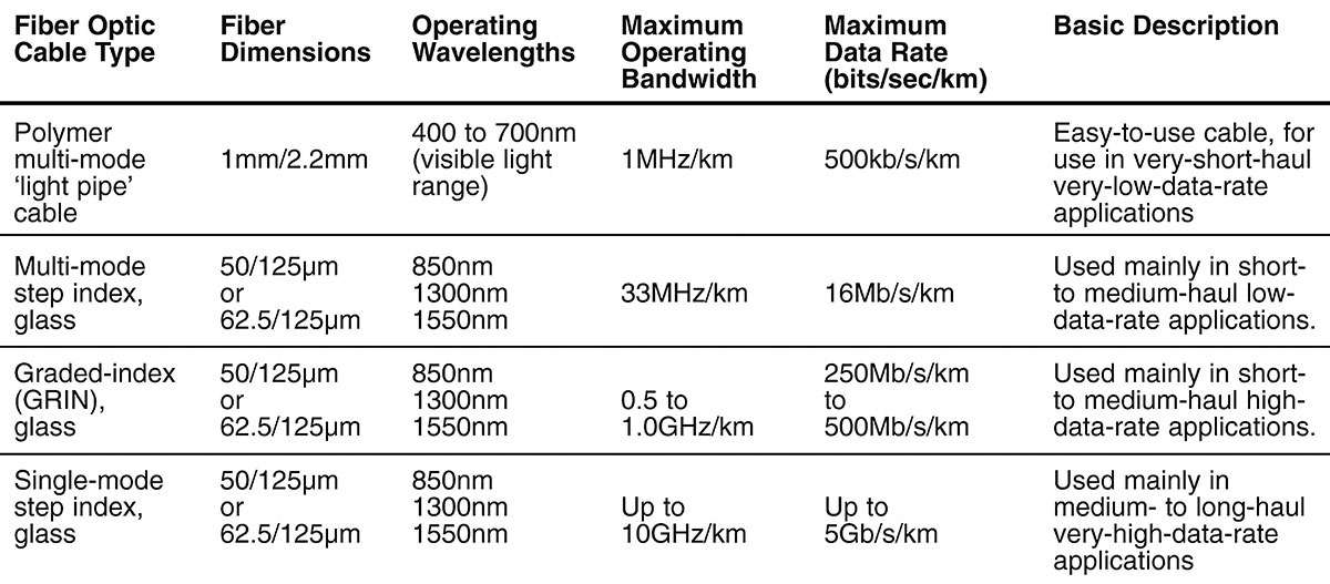
FIGURE 11. Table listing the main features of the four major types of fiber optic cable.
For most high-performance professional uses, glass multi-mode step-index or graded-index (GRIN) cables should be used. Single-mode step-index glass cables are very specialized devices, intended mainly for use in commercial very-high-performance medium- to long-haul applications.
USING FIBER OPTIC CABLE
Figure 12 shows the basic elements that are used in a simple one-way fiber optic communication system. The transmitter (Tx) unit houses a pulse-driven light generator such as a LED or laser diode, which has its output fed into the butt-end input of the cable via a dedicated low-loss coupler.

FIGURE 12. Basic elements of a simple one-way fiber optic communication system.
At the other end of the cable, another low-loss coupler feeds the optical signal into a receiver (Rx) unit that houses a light sensor such as a PIN diode or phototransistor, plus appropriate signal conditioning circuitry.
It is important to note that the fiber optic communication system will only work efficiently if its cable ends are accurately cut and polished, to minimize attenuation losses, and if special low-loss signal couplers are used. Polymer cable is fairly easy to use, and can be cut reasonably well with a very sharp blade.
Glass cable must be cut and polished with the aid of special (and fairly expensive) equipment. A well made coupling gives an attenuation loss of less than 0.5dB; a badly made coupling may give very high attenuation or a complete failure to pass optical signals.
Figure 13 shows a long and more complex one-way fiber optic system that uses splice joints and signal repeaters. Splice joints are used to cleanly join individual cables together, either in the initial cable-laying stages or after making a cable repair, and give a typical coupling loss of about 0.5dB per joint.
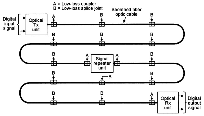
FIGURE 13. Basic elements of a long one-way fiber optic communication system using splice joints and signal repeaters.
Fiber optic cables are supplied on reels; polymer cables have reel lengths of 20 meters; glass multi-mode step-index and GRIN cables have reel lengths of 100 or 500 meters. Thus, a 5km length of GRIN cable typically uses two input/output couplers plus nine splice joints, which give a combined total attenuation loss of 10.5dB, plus that of the actual cable.
Optical signal repeaters are DC-powered and contain an optical Rx input stage, a signal conditioner, and an optical Tx output stage. When inserted into a fiber optic cable system, they can boost a weak and degraded input signal and convert it into a fully-restored strong and clean output signal. Signal repeaters can be used purely as signal boosters, or as signal data-rate (or frequency bandwidth) expanders.
Most fiber optic cable systems are driven by LED or laser diode inputs at power levels in the typical range 0.5mW to 5mW, and when repeaters are used purely as signal boosters in such systems they should be spaced at source-to-repeater ‘attenuation’ intervals of 30dB maximum. In the case of a GRIN system made from 500 meter lengths of cable with an attenuation value of 1.5dB/km, for example, repeaters should be placed at maximum intervals of 10km (25.5dB attenuation) to 12km (30.5dB attenuation).
Note in the above example that if the GRIN cable has a maximum operating data rate of 250 Mbits/sec/km, it will be able to operate at a maximum data rate of 500 Mbits/sec in a 0.5km cable, but at only 25 Mbits/sec in a 10km cable, and so on.
This length-related loss of data rate (and signal bandwidth) can be minimized with the aid of signal repeaters. If these are spaced at 1km intervals along the cable, the data rate will (in this example) not fall below 250 Mbits/sec.
Finally, note that the types of fiber optic cable used in most modern commercial long-haul bi-directional telephone systems are armored and accommodate up to 35 fiber pairs. Each digitized telephonic speech channel operates at a 70-80 kbits/sec data rate, and a cable with a total bit-rate capacity (divided amongst a number of fiber pairs) of 650 Mbits/sec can thus accommodate a total of 8,000 individual speech channels.
Our next (and last) installment of this series will describe the basic operating principles of LEDs and low-power lasers. NV
