This article will show you how to build your very own electronic analog neuron, named the “Perceptron.” Creating a single neuron may not seem earth shattering in the grand scheme of things, considering that your brain has over 1010 of them!
However, a neuron is the fundamental building block of intelligence.
The Perceptron circuit provides a hands-on way to demonstrate the principles of neuron operation, and also allows you to explore basic Boolean logic functions. Last but not least, it is a cool gadget to have sitting on your desk to impress your hacker and/or nerdy friends.
Whether biological, electronic, or software, the basic operation of a neuron is fairly simple at a high level. Of course, a biological neuron is quite a bit more complicated than the others. But relatively speaking, whether we are talking about a brain or neural network program, the basic concept is that the processor is simple by itself, but when combined with many others they collectively perform a complex computation. Compare this to the computer on your desk — how many processors does it have? Essentially one, not counting some special processors in the video card and other peripherals.
Ready, Aim ... Fire!
A neuron receives one or more input signals and produces an output signal (Figure 1).
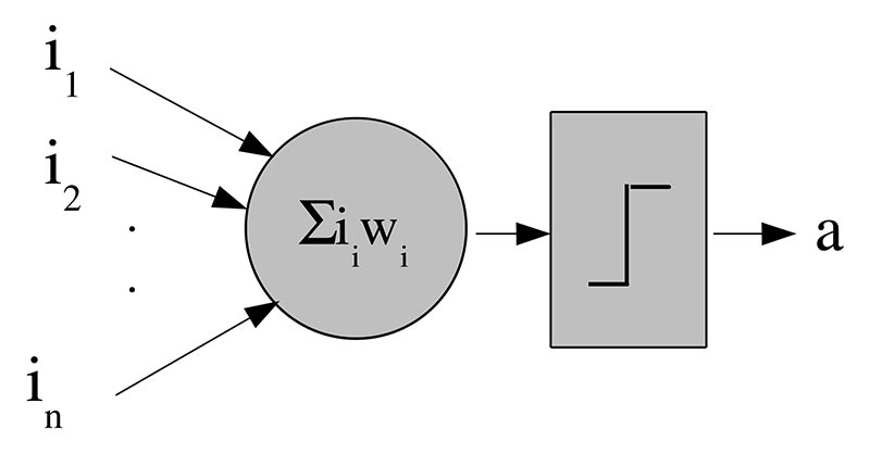
FIGURE 1. Neuron model.
What happens in between comprises the fundamental properties of a neuron — Neuron Property #1 and Neuron Property #2.
Neuron Property #1: A neuron computes a weighted sum of its inputs.
Neuron Property #2: A neuron performs an activation function on the weighted sum.
The activation function, which is also called a “squashing” function in neural network jargon, is usually nonlinear and also serves as a limiting operation to keep the output signal in a bounded range.
Mathematically, the neuron’s operation is represented as:
a = squash(∑(iiwi))
where:
- ii is input i to the Perceptron
- wi is the weight for input i
- a is the activation (output)
- and:
squash(x) = 1; if x > threshold
= 0; otherwise
In English, the weighted sum is computed by multiplying each input by a weighting factor (simply called a weight), which dictates the importance of that input to the neuron’s computation. A small weight means that input is not as important as an input that has a larger weight. The weight may also be negative, which means that the input tends to inhibit the output of the neuron. By summing all of these individual multiplications, we get an output that depends on how big the inputs are and how important each input is (as dictated by its weight).
The second operation is to perform a squashing function on the sum that was calculated in the first step. Neural network researchers experiment with different types of squashing functions, but they generally do two things.
First, they limit the range of the output value, and second, jump suddenly between states. A simple but useful type of squashing function is a simple threshold. If the sum is above a certain value — the threshold — the function jumps to the maximum value, otherwise it jumps to the minimum value.
Decades ago it was realized that in order to perform interesting computations in a neural network, the neuron needed to exhibit this nonlinear behavior.
Our electronic Perceptron is designed to perform this two-step computation of weighted sum plus threshold operation. We will see how this can implement simple, but interesting, functions including simple Boolean logic.
From the outside, the Perceptron consists of two inputs each of which is controlled by a switch and a potentiometer knob. The output is indicated by a single dual-color LED. Inside, an analog amplifier chip and a handful of other components perform the computation. A single 9V battery is used to supply power.
Circuit Operation
The schematic for the Perceptron is shown in Figure 2.
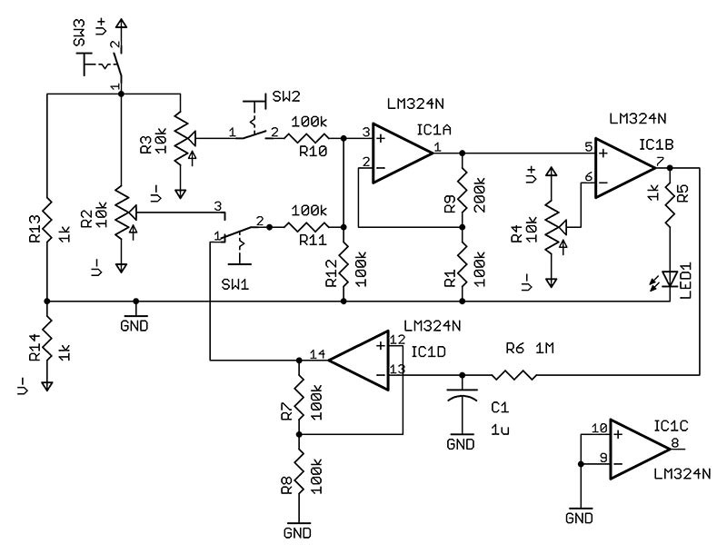
FIGURE 2. Perceptron schematic.
The circuit is based on an LM324 quad op-amp (IC1), which was chosen for its tolerance to supply voltage used. A basic design goal was to have the Perceptron run off a single 9V battery. However, the circuit needs both positive and negative voltages to represent positive and negative weights. Therefore, a single-supply divider consisting of R13 and R14 is used to create a virtual ground and simulate positive and negative voltages.
This is a common op-amp technique, but it is normally advocated for AC signals only. However, by carefully referencing all appropriate signals to the virtual ground, the technique works fine for DC signals.
The first part of the circuit handles the inputs and weights. Since our input signals — as represented by the two toggle switches — are binary (either on or off), we can use a simplifying trick to simulate the weighting operation.
To represent each input weight, potentiometers R2 and R3 are connected across the full supply range. If the pot is turned toward the positive supply rail it represents a positive weight, and a negative weight when turned toward the negative supply. When the pot is in the center of its range, it represents a zero weight. Each toggle switch is used to simply indicate whether an input is active (binary 1) or not (binary 0) by connecting/disconnecting its corresponding pot.
The first op-amp IC1A is configured as a non-inverting summing circuit, to sum the voltages from the two inputs. Resistor R12 is used to tie the summing point to ground in case of no inputs. That takes care of Neuron Property #1. In order to implement Neuron Property #2, we need the squashing function. To realize this, the output of summer IC1A is fed into op-amp IC1B, which is configured as a comparator. The third pot R4 on the negative input sets the threshold of the neuron. Since the amp operates in open loop mode, the high gain will drive the output of the amp to the positive supply if the positive input is above the threshold voltage, and toward the negative supply voltage if it is below. In this mode, it acts mostly as a hard step function, although there is some “play” around the zero voltage point. The LED — with its limiting resistor at the output — indicates whether the output is high or low. The bidirectional LED given in the Parts List results in a green or red signal, which is more interesting than a single-color LED.
This is all that is needed to implement the basic neuron operation. To make things a little more interesting, a third op-amp IC1D from the LM324 is configured as an analog inverter and can be used to feed back the inverted output as an input to the neuron. This can be used to realize a simple oscillator, which will be covered later in the article.
Construction
A printed circuit board pattern is provided in the downloads below if you want to create a PCB along with the parts layout. But you don’t have to take this approach — the circuit can be constructed using simple perfboard and soldered wires. If you are not very good at soldering, you should consider using a 14-pin socket and place the chip in after you are done soldering. If you use a socket, it is easier to solder this in first — otherwise you can save soldering the IC for later in order to minimize the risk of heat damage.
Next, solder the resistors and capacitor to the board, followed by the 9V battery clip. You don’t have to be paranoid about too much when soldering but as always, you should try to make good solder connections. The rest of the components — switches, pots, and LED — will be soldered using insulated wire. I like to use hookup wire scavenged from a ribbon cable. The wires are thin and flexible and I can peel off as many conductors as I want for the particular component I am connecting. However, feel free to use single insulated wires or multiconductor hookup wire.
It is always good to double-check the supply and ground connections on the chip and battery connections, especially if you are using perfboard.
The Parts List includes a case with a battery compartment that the circuit can be built into.
Parts List
| SEMICONDUCTORS |
| IC1 |
LM324N quad op-amp |
| LED1 |
T1 3/4 dual color red/green, two-lead LED |
| RESISTORS (all 1/4W, 5%) |
| R1, R7, R8, R10-R12 |
100K |
| R5 |
470Ω |
| R6 |
1M |
| R9 |
220K |
| R13, R14 |
1K |
| R2-R4 |
10K linear pot |
| CAPACITORS |
| C1 |
1 µF 16V ceramic or other nonpolarized |
| ADDITIONAL PARTS AND MATERIALS |
| SW1 |
SPDT center off submini toggle switch |
| SW2-3 |
SPST submini toggle switch |
| Knobs (to fit potentiometers), case (PacTec HM-9VB 4” x 2 1/2” x 1” or similar), LED holder, 9V battery connector, PCB or perf board, 14-pin socket, ribbon cable or other hookup wire, 9V battery |
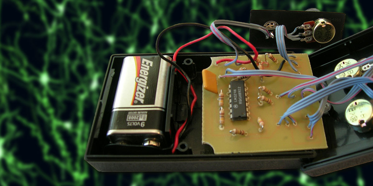
Figure 3 shows the completed circuit board inside its enclosure.
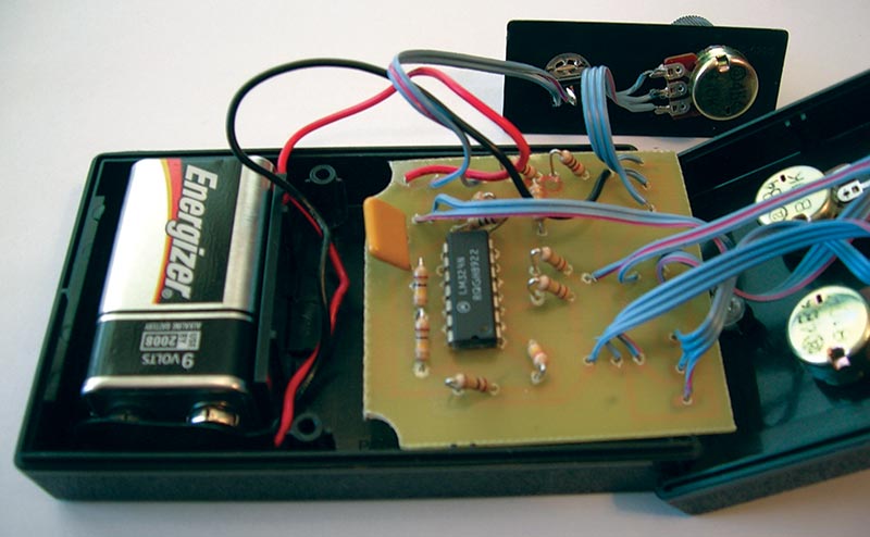
FIGURE 3. Circuit board in enclosure.
For the case listed in the Parts List, it was necessary to remove some material from two of the corners of the PCB. Figure 4 shows the completed Perceptron.
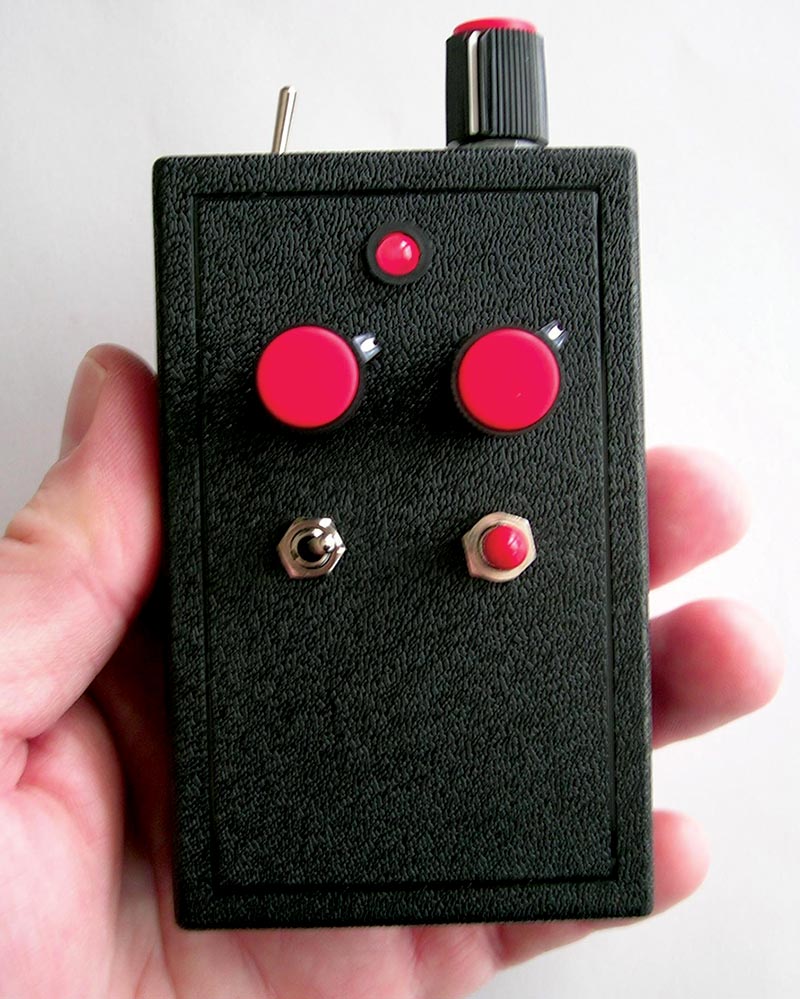
FIGURE 4. Finished unit.
Testing and Using the Perceptron
The inputs of the Perceptron are controlled by a switch and a potentiometer (knob). Each knob controls the weight on its corresponding input. Clockwise is intended to be positive and counterclockwise is negative, with the middle of the range being approximately zero or “no weight.” The switches are used to indicate if the input is “on” or not. You may have to experiment with the switches to get them in the right polarity.
There is also an important note on the switch for input 1. You probably noticed that it is a different type of switch. This switch actually has three positions: the center is “off” and when you move the toggle either way, it selects one of two inputs. The first input is the normal input and the second is a feedback signal from the output, which we will talk about later. The third knob is the threshold knob, which — amazingly — sets the threshold of the neuron.
You will want to make sure your potentiometers are connected in the right polarity. You want full counterclockwise to connect the center lead to the negative supply voltage and clockwise to connect to the positive supply. If you have a multimeter, you can easily verify this by varying the knob and checking the voltage on the center lead. Without using a meter, you will have to experiment a bit.
First (since we are using a dual color LED), if the power switch is on and all battery and power connections are good, the LED should show some color. Next, as a simple test, put all knobs in the middle of the range. Now vary the threshold knob back and forth — it should cause the LED to change between green and red.
Now, set the threshold knob in the middle of its range. Set input switch SW1 to its middle position. Now vary the input 2 knob. If nothing changes, then the input switch SW1 is off. Switch it the other way and vary the knob. If you do not see a change now, then you should go back and check your wiring. Next, tTurn the input 2 switch back off and try the same thing with input 1. Another thing to check is the polarity of the LED — a positive output is intended to show as green.
The Perceptron can be used to emulate simple Boolean logic gates. First we will try an OR gate, which has a truth table as shown in Figure 5.
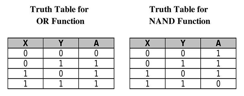
FIGURE 5. Boolean logic tables.
In Perceptron terms, the output will be on (green) if either input is on. To configure the Perceptron for this operation, set the threshold knob to a little over halfway and each weight knob well over halfway. Now try the switches in different combinations. With either switch on, you should see a strong green light. Now try a NAND gate configuration. For this function, set the threshold knob most of the way counterclockwise and set the weight knobs a little more clockwise than the threshold.
The idea is that the threshold is strongly negative and each weight is somewhat negative. In this way, there will be a positive output unless both inputs are on and combine to drive the sum below the threshold.
A Neural Oscillator
Now, let’s talk about the third setting of switch SW1. Our Perceptron is a highly idealized model of a real biological neuron, and it would take some complex electronics to model all of its functions. However, the Perceptron does include one additional behavior, which brings us to an interesting fact — Neuron Property #3.
Neuron Property #3: A neuron has a built-in time delay.
A neuron’s operation is a complex function of time, but for our purposes we will consider a simple time delay. As with all real world devices, a neuron cannot instantaneously produce an output and, in fact, operates quite slowly (on the order of milliseconds) compared to electronic circuits (nanoseconds). But as we will see shortly, time delays are actually useful in the same way that clocking functions are critical to digital circuit operation.
One of the extra amps on the LM324 chip has been used to create a second neuron. This neuron only has a single input which is the output of the first neuron. But it also has a time delay, which is implemented by the combination of C1 and R6. When switch SW1 is moved to its third position, it connects an inverted version of the first neuron’s output back as an input to itself. However, because of the delay circuit, this doesn’t happen until after about a second. Since the signal is inverted, it causes the first neuron to change its state, and then keep switching back and forth about once a second. The result is a simple oscillator that has been created using only neurons.
Wrapping Up
If you are new to the concept of neurons and neural networks, the Perceptron offers a practical hands-on introduction to a neuron’s operation. If you are a seasoned pro, I think you will find it to be an entertaining diversion that is simple to build, and makes a fun accessory for your desk. NV
About the Author
Christopher McCarley is currently a software architect at Viziqor Solutions. He has done postgraduate research in VLSI analog neural network design and has over 20 years experience developing a variety of technologies including middleware, robotics, and laser systems.
Downloads
The Perceptron Circuit.zip
What’s in the zip?
Parts Layout and PCB pattern files