A triac is a controllable medium- to high-power semi-latching solid-state AC power switch. This two-part article explains its basic operation and shows various ways of using it. Most of the practical circuits show two sets of component values for use with normal domestic/commercial 50Hz or 60Hz AC voltage supplies with nominal values of either 240V (as used in most of Europe) or (in parenthesis) 120V (as used in most of the USA). In each design, the user must use a triac with ratings to suit his or her own particular application.
Triac Basics
A triac is a three-terminal (MT1, gate, and MT2) solid-state thyristor that uses the alternative symbols in Figure 1 and acts like a pair of SCRs wired in inverse parallel and controlled via a single gate terminal.
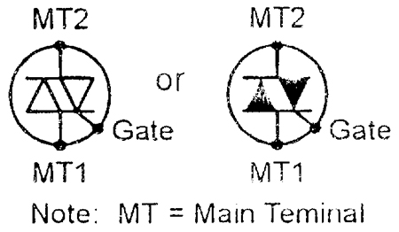
FIGURE 1. Triac symbols.
It can conduct current in either direction between its MT1 and MT2 terminals and can thus be used to directly control AC power. It can be triggered by either positive or negative gate currents, irrespective of the polarity of the MT2 current, and it thus has four possible triggering modes or 'quadrants,' signified as follows:
I+ Mode = MT2 current +ve, gate current +ve
I- Mode = MT2 current +ve, gate current -ve
III+ Mode = MT2 current -ve, gate current +ve
III+ Mode = MT2 current -ve, gate current -ve
The trigger current sensitivity is greatest when the MT2 and gate currents are both of the same polarity (either both positive or both negative), and is usually about half as great when they are of opposite polarity.
Figure 2 shows a triac used as a simple AC power switch, driving a resistive lamp load; assume that SW2 is closed.
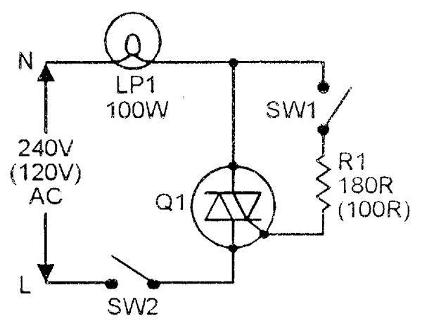
FIGURE 2. Simple AC power switch with resistive (lamp) load.
When SW1 is open, the triac acts as an open switch and the lamp passes zero current. When SW1 is closed, the triac is gated on via R1 and self-latches shortly after the start of each half-cycle, thus switching full power to the lamp load. The triac automatically unlatches at the end of each AC half-cycle as the instantaneous supply voltage (and thus the load current) briefly falls to zero.
In Figure 2, the task of R1 is that of limiting the peak instantaneous switch-on gate current of the triac to a safe value; its resistance (combined with that of the load) must be greater than the peak supply voltage (roughly 350V in a 240V AC circuit, 175V in a 120V circuit) divided by the triac's peak gate current rating (which is usually given in the triac manufacturer's extended data sheets).
Note in Figure 2 (and in most other triac circuits shown in this mini-series) that — for safety reasons — the load is wired in series with the AC supply's neutral (N) line, and master on/off switch SW2 can isolate the entire circuit from the live (L) line.
Triac Rate Effect
Most triacs, like SCRs, are susceptible to 'rate-effect' problems. Internal capacitances inevitably exist between the main terminals and gate of a triac, and if a sharply rising voltage appears on either main terminal it can — if its rate-of-rise exceeds the triac's dV/dt rating — cause enough break-through to the gate to trigger the triac on. This unwanted 'rate-effect' turn-on can be caused by supply line transients; the problem is, however, particularly severe when driving inductive loads such as electric motors, in which load currents and voltages are out of phase, thus making a large voltage suddenly appear on the main terminals each time the triac unlatches as its main terminal current falls to near-zero in each operating half-cycle.
Rate-effect problems can usually be overcome by wiring an R-C 'snubber' network between MT1 and MT2, to limit the voltage rate-of-rise to a safe value, as shown (for example) in the triac power switch circuit in Figure 3, where R2-C1 form the snubber network.
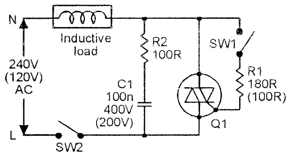
FIGURE 3. Simple AC power switch with inductive load and C1-R2 snubber network to give rate effect suppression.
Some modern triacs have enhanced dV/dt ratings (typically 750V/mS) and are virtually immune to rate-effect problems; these triacs are known as 'snubberless' types.
RFI Suppression
A triac can be used to give variable AC power control by using a 'phase-delayed switching' technique, in which the triac is triggered part-way through each half-cycle. Each time the triac is gated on, its load current switches sharply (in a few microseconds) from zero to a value set by its load resistance and instantaneous supply voltage values. In resistively loaded circuits such as lamp dimmers, this switching action inevitably generates a pulse of RFI, which is least when the triac is triggered close to the 0° and 180° 'zero crossing' points of the supply line waveform (at which the switch-on currents are minimal), and is greatest when the device is triggered 90° after the start of each half cycle (where the switch-on currents are at their greatest).
The RFI pulses occur at twice the supply line frequency, and can be very annoying. In lamp dimmers, RFI can usually be eliminated by fitting the dimmer with a simple L-C filter network as shown in Figure 4.
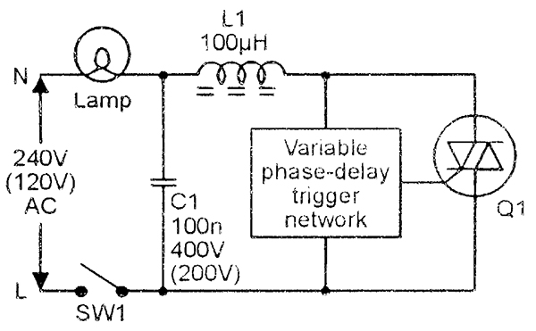
FIGURE 4. Basic AC lamp dimmer with RFI suppression via C1-L1.
The filter is fitted close to the triac, and greatly reduces the rate-of-rise of the AC power line currents.
Diacs and Quadracs
A diac is a two-terminal bidirectional trigger device; it can be used with voltages of either polarity and is usually used in conjunction with a triac; Figure 5 shows its circuit symbol.
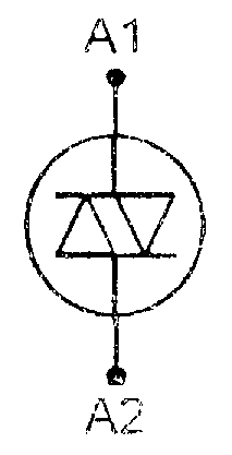
FIGURE 5. Diac symbol.
The diac's basic action is such that, when connected across a voltage source via a current-limiting load resistor, it acts like a high impedance until the applied voltage rises to about 35V, at which point it triggers and acts like a low-impedance 30V zener diode, and 30V is developed across the diac and the remaining 5V appears across the load resistor. The diac remains in this state until its forward current falls below a minimum holding value (this occurs when the supply voltage falls below the 30V 'zener' value), at which point the diac turns off again.
The diac is most often used as a trigger device in phase-triggered triac variable power control applications, as in the basic lamp dimmer circuit of Figure 6.
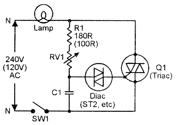
FIGURE 6. Basic diac-type variable phase-delay lamp dimmer circuit.
Here, in each power line half-cycle, the R1-RV1-C1 network applies a variable phase-delayed version of the half-cycle to the triac gate via the diac, and when the C1 voltage rises to 35V, the diac fires and delivers a 5V trigger pulse (from C1) into the triac gate, thus turning the triac on and simultaneously applying power to the lamp load and removing the drive from the R-C network. The mean power to the load (integrated over a full half-cycle period) is thus fully variable from near-zero to maximum via RV1.
In the early development days of the triac, some specialist devices were manufactured with a built-in diac in series with the triac gate; such devices were known as quadracs and used the Figure 7 circuit symbol.
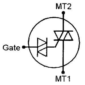
Figure 7 . Quadrac symbol.
Quadracs were not a commercial success, and are now obsolete.
AC Power Switch Variations
The simplest type of triac power switch is that of Figure 2, in which the triac is gated on via R1 when SW1 is closed; only 1V or so is generated across the triac when it is on, so R1 and SW1 consume very little mean power; Figure 3 shows the same circuit fitted with a 'snubber' network. There are many useful variations of these basic circuits. Figure 8, for example, shows a version that can be triggered via an AC-derived DC supply.
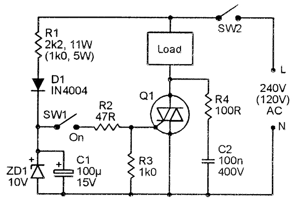
FIGURE 8. AC power switch with AC-derived DC triggering.
C1 charges (via R1-D1) to +10V on each positive AC power line half-cycle, and this charge triggers the triac when SW1 is closed. Note that R1 is subjected to almost the full AC line voltage at all times, and thus needs a fairly high power rating, and that all parts of this circuit are 'live,' making it difficult to interface to external control circuitry.
Figure 9 shows the above circuit modified to give 'isolated' interfacing to external control circuitry.
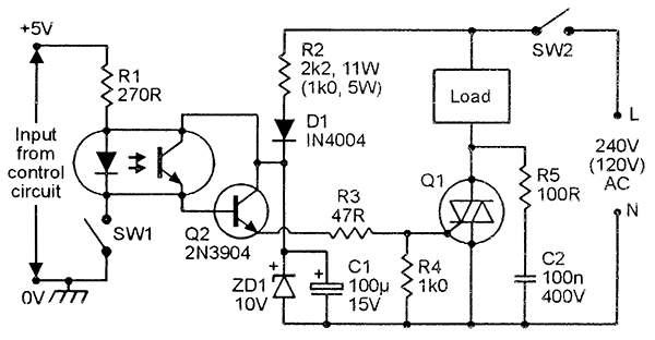
FIGURE 9. Isolated-input (optocoupled) AC power switch, DC triggered.
SW1 is simply replaced by transistor Q2, which is driven from the phototransistor side of an optocoupler. The coupler's LED is driven via an external DC supply via R1, and the triac turns on only when SW1 is closed; SW1 can be replaced by electronic switching circuitry, if desired.
Figure 10 shows a variation in which the triac is AC triggered in each half-cycle via the AC impedance of C1-R1 and via back-to-back zeners ZD1-ZD2, and C1 dissipates near-zero power.
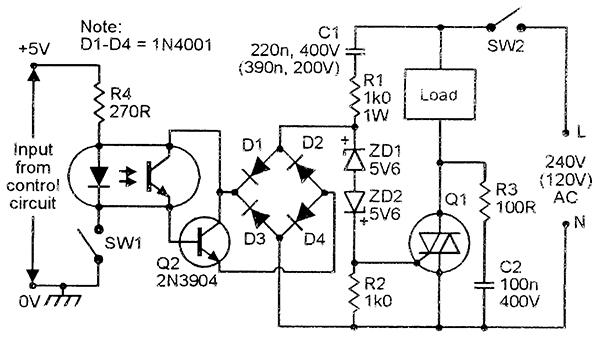
FIGURE 10. Isolated-input AC power switch, AC triggered.
Bridge rectifier D1-D4 is wired across the ZD1-ZD2-R2 network and is loaded by Q2. When Q2 is off, the bridge is effectively open and the triac is gated on in each half-cycle, but when Q2 is on, a near-short appears across ZD1-ZD2-R2, and the triac is off. Q2 is driven via the optocoupler from the isolated external circuit, and the triac is on when SW1 is open and off when SW1 is closed.
Figures 11 and 12 show variations in which the triac is triggered via a transformer-derived DC supply and a transistor-aided switch. In Figure 11, Q2 and the triac are both driven on when SW1 is closed, and are off when SW1 is open.
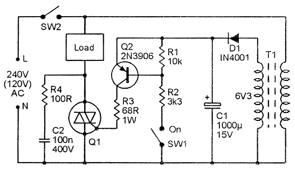
FIGURE 11. AC power switch with transistor aided DC triggering.
In practice, SW1 can be replaced by electronic circuitry, enabling the triac to be activated via heat, light, sound, time, etc. Note, however, that the whole of this circuit is 'live.' Figure 12 shows the circuit modified for optocoupler operation, enabling it to be activated via fully-isolated external circuitry.
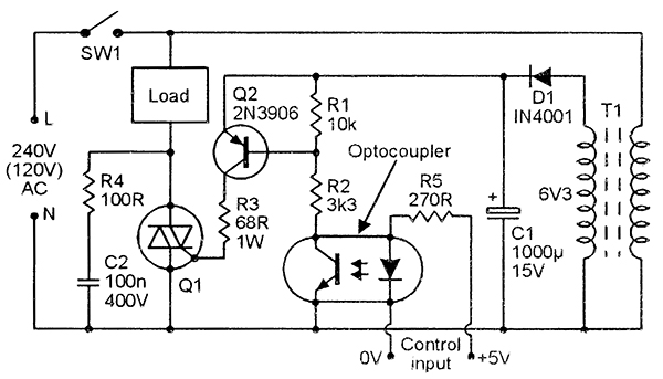
FIGURE 12. Isolated-input AC power switch with DC triggering.
UJT Triggering
Another way to obtain fully-isolated triac switching is via the UJT circuits in Figures 13 and 14, in which the UJT is an old 2N2646 type or a modern near-equivalent. In these circuits, the triggering action is obtained via UJT oscillator Q2, which operates at several kHz and feeds output pulses to the triac gate via pulse transformer T1, which provides the desired 'isolation.' Because of its fairly high oscillating frequency, the UJT triggers the triac within a few degrees of the start of each AC power-line half-cycle when the oscillator is active.
In Figure 13, Q3 is in series with the UJT's main timing resistor, so the UJT and triac turn on only when SW1 is closed.
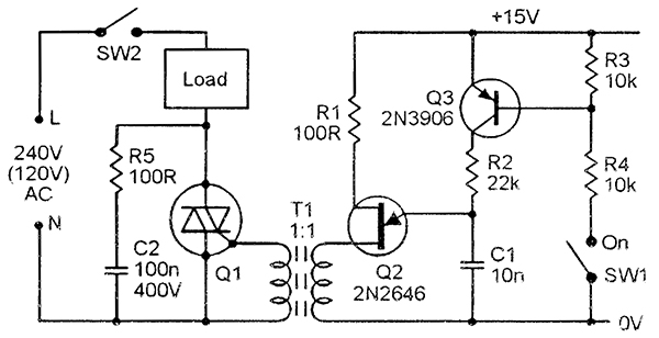
FIGURE 13. Isolated-input (transformer-coupled) AC power switch.
In Figure 14, Q3 is wired in parallel with the UJT's main timing capacitor, so the UJT and triac turn on only when SW1 is open.
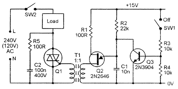
FIGURE 14. Isolated-input AC power switch.
Optocoupled Triacs
The gate junctions of a 'naked' triac are inherently photosensitive, and an optocoupled triac can thus be made by mounting a 'naked' triac and LED close together in a single package. Figure 15 shows the outline and lists the characteristics of a typical six-pin DIL version of such a device, in which the LED has a maximum current rating of 50mA, the triac has maximum ratings of 400V and 100mA RMS (and a surge current rating of 1.2A for 10mS), and the entire package has an isolating voltage rating of 1.5kV and a typical input current trigger sensitivity of 5mA.

FIGURE 15. Typical optocoupled triac outline and operating characteristics.
Optocoupled triacs are easy to use and provide excellent electrical isolation between input and output. The input is used like a normal LED, and the output like a low-power triac. Figure 16 shows the device used to activate an AC line-powered filament lamp, which must have an RMS rating below 100mA and a peak inrush current rating below 1.2A.
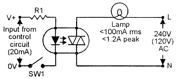
Figure 16. Low-power lamp control via an optocoupled triac.
Figure 17 shows an optocoupled triac used to activate a slave triac, thereby driving a load of any desired power rating.

FIGURE 17. High-power control via a triac slave.
This circuit is suitable for use only with non-inductive loads such as lamps and heating elements. It can be modified for use with inductive loads such as electric motors by using the connections in Figure 18.
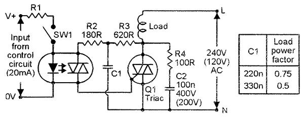
FIGURE 18. Driving an inductive load.
Here, the R2-C1-R3 network provides a degree of phase-shift to the triac gate-drive network, to ensure correct triac triggering action, and R4-C2 form a snubber network to suppress rate effects.
Synchronous 'Zero-Voltage' Power Switching
A synchronous 'zero-voltage' (or 'integral cycle') power switch is one in which the triac invariably turns on just after the start of each power half-cycle (i.e., near the waveform's zero-voltage point) and then turns off again automatically at the end of it, thus generating minimal RFI. In most power switching circuits shown so far in this article, the triac turns on at an arbitrary point in its initial switch-on half-cycle, thus producing a potentially high initial burst of RFI, but then gives a synchronous zero-voltage switching action on all subsequent half-cycles.
A truly synchronous zero-voltage circuit uses the switching system in Figure 19, in which the triac can only be gated on near the start or 'zero-voltage' point of each half-cycle, and thus produces minimal RFI.
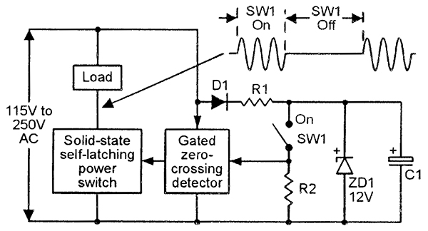
FIGURE 19. Synchronous zero-voltage AC power switching system.
This system is widely used to give on/off control of high-current loads such as electric heaters, etc.
Figure 20 shows a practical synchronous zero-voltage AC power switch; 10V DC is AC-derived via R7-D1-ZD1 and C2 and is switched to the triac gate via Q2, which is controlled via SW1 and 'zero-voltage' detector Q3-Q4-Q5 and can supply gate current only when SW1 is closed and Q3 is off.

FIGURE 20. Synchronous AC power switch.
In the zero-voltage detector, Q4 or Q5 are driven on whenever the AC line voltage is more than a few volts (set by RV1) above or below zero, thereby driving Q3 on via R5 and inhibiting Q2. Thus, gate current can only be fed to the triac when SW1 is closed and the instantaneous AC line voltage is within a few volts of zero; this circuit thus generates minimal switching RFI.
Figure 21 shows the circuit modified so that the triac can only turn on when SW1 is open.
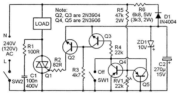
FIGURE. 21 Alternative version of the synchronous AC power switch.
Note in both cases that only a narrow pulse of gate current is fed to the triac, and the mean gate current is thus only 1mA or so. SW1 can be replaced by an electronic switch or optocoupler, if desired, thus enabling the load to be activated by light or temperature levels or by time, etc.
In practice, the simplest way of making a really efficient synchronous 'zero-voltage' triac-driving circuit is with the aid of a special-purpose IC that functions as an optocoupled low-power synchronous 'zero-voltage' triac that can easily be used as a slave for synchronously driving a normal high-power triac.
The next, and final, episode will give practical details of such circuits, together with other triac-related circuits and information. NV