Our first episode of this two-part feature explained triac basics, looked at various practical triac power switching circuits, introduced optocoupled triacs, and explained basic synchronous 'zero-voltage' power switching principles. Part 1 concluded by pointing out that the simplest way of making a really efficient synchronous 'zero-voltage' triac-driving circuit is with the aid of a special-purpose IC that functions as an optocoupled low-power synchronous 'zero-voltage' triac that can easily be used as a slave for synchronously driving a normal high-power triac. This final episode gives practical details of such circuits, together with other triac-related circuits and information.
Optocoupled synchronous power switching
Synchronous 'zero-voltage' triac-driving circuits are widely used in modern electric heating and filament-lamp lighting control systems. Until fairly recently, several companies produced special synchronous 'zero-voltage' triac-gating ICs for use in such applications; the best known of these ICs were the CA3059 (from RCA) and the TDA1024 (from Signetics), which each had built-in AC-derived DC power supply circuitry, a zero-crossing detector, triac gate drive circuitry, and a high-gain differential amplifier/gating network.
In the mid-1990s, however, all of these ICs were made obsolete by the introduction of a new and modestly-priced type of IC that functions as an optocoupled low-power synchronous 'zero-voltage' triac that can easily be used as a slave for synchronously driving normal high-power triacs.
Several companies (including Isocom, Motorola, Sharp, Siemens, and Toshiba) manufacture optocoupled synchronous zero-voltage triacs. Most of these devices take the form of a six-pin DIL IC, as shown in Figure 1, and house a simulated triac that has its gate drive controlled via an integral photosensitive zero-crossing detector (ZCD), which can be remotely energized via an integral LED.
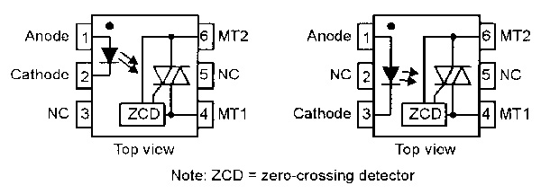
FIGURE 1. Typical optocoupled synchronous 'zero-voltage' triac outlines and pin notations.
Typically, this type of optocoupled triac has maximum AC ratings of 400V peak and 100mA RMS (with a surge rating of 1.2A for 10mS), will only trigger when the instantaneous AC voltage is below a fixed zero-cross inhibit voltage (VIH) value of ±15V nominal (±25V maximum), has a maximum LED forward current rating of 60mA, has a typical input current trigger sensitivity of 8mA or less, and the entire package has an isolating voltage rating of several kV.
Optocoupled synchronous zero-voltage triacs are easy to use and provide excellent electrical isolation between input and output. The input is used like a normal LED, and the output like a low-powered triac. In most practical applications, the optocoupled triac is used to activate the gate of a 'slave' triac, thereby driving a resistive AC load of any desired power rating. Figure 2 shows a practical circuit of this type, which can be manually or automatically switched on or off via a DC input current. Note in Figure 2 that R1 is used to limit the peak switch-on current of the optocoupled triac (and thus the peak gate current of Q1) at IC1's absolute maximum VIH value minus 2V, i.e., typically at 23V; with the R1 value shown, the peak switch-on current is limited to 280mA.
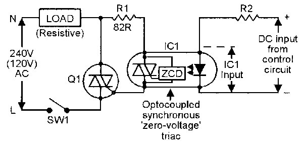
FIGURE 2. Basic power switching circuit using an optocoupled synchronous 'zero-voltage' triac.
R2 is used to limit the LED input current of IC1 to a sensible working value.
Figure 3 shows one way of incorporating the above circuit in a complete electric power switching system.
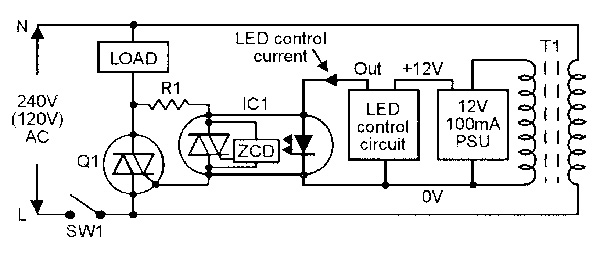
FIGURE 3. Basic power switching system using an optocoupled synchronous 'zero-voltage' triac.
Here, when SW1 is closed, the AC power line is connected to both the load/Q1 circuitry and to the primary of low-power transformer T1, which has its output converted into a 12V DC supply that powers IC1's LED control circuit, which is electrically fully isolated from the AC supply. The LED control circuit can take any of a variety of forms; some simple examples are shown in Figures 4 to 7. The simplest LED control circuit that can be used in the Figure 3 system consists of an on/off toggle switch that — when closed — connects the IC1 LED to the 12V DC supply via a 680R resistor that limits the LED 'on' current to about 15mA, thereby switching the electric load fully on.
Figure 4 shows a dual push-button LED control system, in which the LED and load turn on when S1 is briefly closed, and off when S2 is briefly closed. Here, CMOS NOR gates IC1a-IC1b are wired as a manually triggered bistable multivibrator that has its output buffered by emitter follower Q1 and latches into the 'output high' state when S1 is briefly closed, thereby energizing the circuit's red LED via R3 and feeding a 15mA control current to the LED input of the optocoupled triac. The bistable latches into the 'output low' state when S2 is briefly closed, thereby killing the DC power feeds to the red LED and the triac.
The Figure 4 circuit gives purely manual on/off LED control of an electrical power load such as a heater.
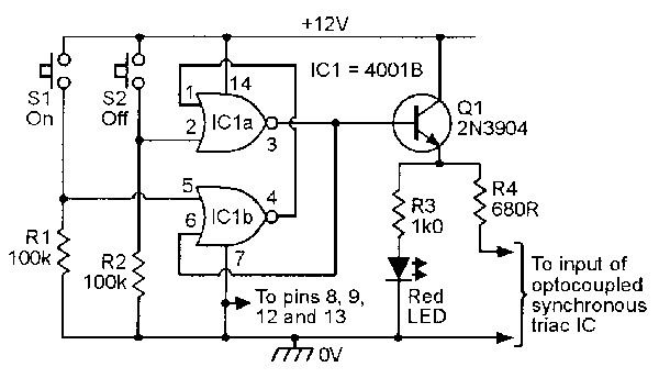
FIGURE 4. Dual push-button LED control circuit for use in the Figure 3 system.
Figure 5 shows a simple circuit that also provides the option of automatic control via an adjustable thermostat switch that is normally closed but opens when its temperature exceeds a selected value.
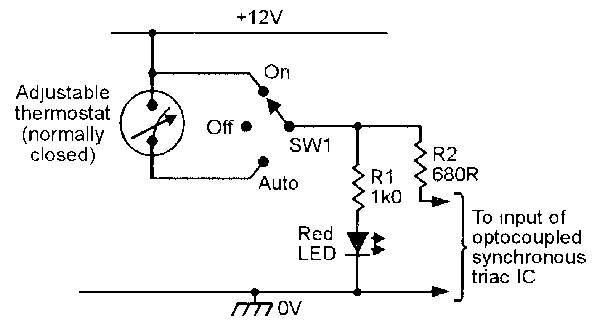
FIGURE 5. 'Thermostat' LED control circuit for use in the Figure 3 system.
Here, the red LED and the electric heater are off when SW1 is in the 'off' position or in the 'auto' position when the thermostat is open, but are on when SW1 is in the 'on' position or in the 'auto' position when the thermostat is closed.
Figures 6 and 7 show high-precision versions of the basic Figure 5 circuit, with the thermostat replaced by a temperature-sensitive electronic switching circuit. The Figure 6 circuit uses an ordinary silicon diode (D1) as a thermal sensing element. Here, zener diode ZD1 is wired in series with R1 so that a constant 5.6V is developed across the two potential dividers formed by R2-R3-RV1-RV2, and R4-D1, and a near-constant current thus flows through each of these dividers. A constant reference voltage is thus developed (via RV1) between the R1-ZD1 junction and pin 2 of the 741 op-amp, and a temperature-dependent voltage with a coefficient of -2mV/°C is developed between the R1-ZD1 junction and pin 3 of the op-amp. Thus, a differential voltage with a coefficient of -2mV/°C appears between pin 2 and pin 3 of the op-amp, which is wired as a high-gain (open loop) voltage comparator with slight hysteresis applied via R6.
In Figure 6, RV1 is a linear rotary pot that is used to manually adjust the heater system's operating temperature over a ±10°C (nominal) range, and RV2 is a multiturn preset that is used to set the circuit's nominal (with RV1 at mid-scale setting) trip temperature.
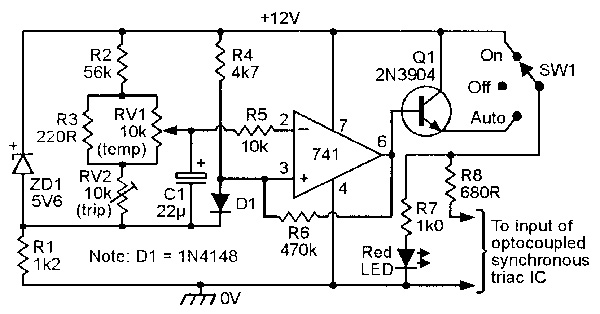
FIGURE 6. Automatic LED control circuit, using a silicon diode as a temperature-sensing element, for use in the Figure 3 system.
To initially set up the circuit, set RV1 to mid-scale, adjust the temperature of D1 to the desired mid-scale trip value, then trim RV2 so that the red LED is on, but goes off again if the D1 temperature is increased slightly (by briefly applying finger heat to D1). In practice, the circuit has a typical switching sensitivity of about 0.5°C. The Figure 7 circuit uses an inexpensive NTC (negative temperature coefficient) bead or disc thermistor, with a nominal resistance of 4k7 at 25°C, as its thermal sensing element.
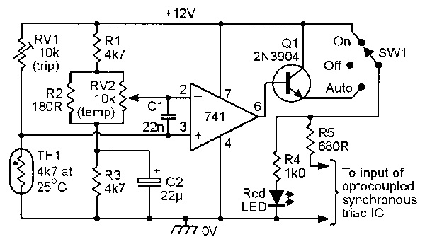
FIGURE 7. Automatic LED control circuit, using a NTC thermistor as a temperature-sensing element, for use in the Figure 3 system.
Here, potential divider RV1-TH1 applies a temperature-sensitive voltage to pin 3 of the 741 op-amp, and potential divider R1-R2-RV2-R3 applies a preset reference voltage to pin 2 of the op-amp. The two potential dividers are actually wired in the form of a Wheatstone bridge, and the op-amp is used as a high-gain bridge balance detector; the bridge balance point is unaffected by variations on supply voltage. Capacitors C1 and C2 help to ensure circuit stability.
The action of the Figure 7 circuit is such that (when SW1 is in the Auto position) the output of SW1 is normally low but switches high and activates the red LED and the external triac when the TH1 temperature is below a value pre-set via RV1 and RV2.
RV2 is a linear rotary pot that is used to manually adjust the heater system's operating temperature over a limited range, and RV1 is a multiturn preset that is used to set the circuit's nominal (with RV2 at mid-scale setting) trip temperature. To initially set up the circuit, set RV2 to mid-scale, raise the temperature of TH1 to the desired mid-scale trip value, then trim RV1 so that the red LED is on, but goes off if the TH1 temperature is increased slightly.
Note that the Figure 7 circuit has a typical switching sensitivity similar to that of the Figure 6 design (about 0.5°C), but that its thermistor has a far longer thermal time constant than the sensing diode of the Figure 6 circuit; the Figure 7 circuit is thus slower-acting than the Figure 6 circuit. Also note (in Figure 7) that the thermal 'span' range of RV2 can be increased (or reduced) by increasing (or reducing) the value of resistor R2.
Finally, note that — in all cases where an 'automatic' heater-control circuit is used to regulate the temperature of a room — the actual thermal sensor device (thermostat, thermistor, or sensing diode) must be sited roughly one meter above floor level, in a position where it can directly and safely sense the temperature of normally-circulating air; this position must be free of drafts or direct radiation from the heater, and must not be obstructed by furniture, etc.
'Burst fire' AC power control principles
There are three basic ways of controlling the AC power feed to resistive loads such as filament lamps or electric heaters via a triac. One of these is the variable phase-delay-switching system, which gives fully-variable power control and is often used in lamp dimmers, but generates substantial RFI and is thus unsuitable for driving high-power (greater than about 200W) loads. The second is the synchronous zero-voltage power switching system (see last month's Figure 19), which generates minimal RFI but gives only a simple on/off — rather than fully-variable — type of power control.
The third method of AC power control is the burst-fire integral-cycle system shown in Figure 8, in which bursts of complete half-cycles are fed to the load at regular line-frequency-related intervals.
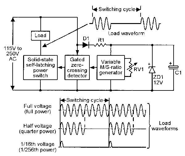
FIGURE 8. Burst-fire (integral cycle) AC power controller.
Thus, if bursts are repeated at eight-cycle intervals, the mean load voltage equals the full supply line value if the bursts are of eight-cycle duration, or half voltage (equals quarter power) at four-cycle duration, or one-sixteenth voltage (equals 1/256th power) at one half-cycle duration, etc. The burst-fire system thus gives variable power control and generates minimal RFI, and is often used to control the thermal output of electric heaters. Note that the burst-fire integral-cycle control system operates on the synchronous 'zero-voltage' triac switching principle, and practical circuits of this type can thus be made by using suitable control circuitry in conjunction with the basic power switching system of Figure 3. Two suitable circuits are shown in the next section of this article.
'Burst-fire' heater control circuits
The optocoupled synchronous circuits shown in Figures 2 to 7 all — when powering a heater load — give a simple form of control in which the heater is either fully off or is operating at maximum power. Figures 9 and 10 show circuits that drive the heater in the synchronous burst-fire mode, thus enabling the heater's thermal output to be varied over a wide range. The Figure 9 circuit enables the heater's thermal output to be varied manually, via RV1.
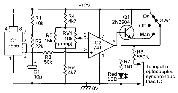
FIGURE 9. Manually variable 'burst-fire' LED control circuit for use in the Figure 3 system.
The Figure 10 circuit varies the heater's output automatically, to maintain a room's temperature at a precise pre-set value.
The operation of the Figure 9 circuit is fairly simple. Here, IC1 (a CMOS version of the 555 'timer' IC) is wired in the astable mode and generates a repeating ramp waveform across C1. This waveform has a period of about 680mS (thus spanning roughly 68 half-cycles of a 50Hz power line waveform or 82 half-cycles of a 60Hz waveform during each period) and is centered on half-supply volts and swings symmetrically between 1/3rd and 2/3rds of supply voltage value. This waveform is fed to pin 3 of op-amp IC2 via R3, and linear rotary pot RV1 feeds a DC reference voltage that is variable from below 1/3rd to above 2/3rds of the supply voltage value to pin 2 of the op-amp, which is configured as a high-gain voltage comparator.
The net effect of the above circuitry is that IC2 converts the 680mS ramp waveform into a switched rectangular output waveform with a mark/space (M/S) ratio that is fully variable from 0:1 (output low for the full 680mS period) to 1:0 (output high for the full 680mS period) via RV1. When SW1 is switched to the Man (manual) position, this output is fed to the input of the Figure 3 optocoupled synchronous electric heater control system, where it enables the mean power input to the heater to be varied (via RV1) from zero to maximum in 68 discrete 'half-cycle' steps in a 50Hz system or 82 steps in a 60Hz system.
Finally, to complete this look at burst-fire heater control circuits, Figure 10 shows a self-regulating synchronous burst-fire heater controller that automatically varies the heater's input power to maintain a room's temperature at a precise pre-set value.
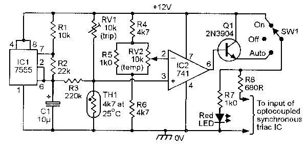
FIGURE 10. Fully automatic 'burst-fire' LED control circuit for use in the Figure 3 heater control system.
Here, the circuit to the right of R3 is almost the same as the Figure 7 thermistor-controlled automatic circuit, but the IC1 circuit to the left of R3 is taken directly from the Figure 9 circuit and superimposes a 680mS ramp waveform (with a peak-to-peak amplitude of about 40mV) on the RV1-TH1 junction and pin 3 of IC2.
The net effect of the above combination is that the external heater is turned fully on (via the optocoupled triac in the Figure 3 system) if the TH1 temperature is more that (say) 1°C below a pre-set value, or fully off if it is more that 1°C above the pre-set value, but is operated in the burst-fire mode — with its M/S ratio automatically adjusted via TH1 — when the TH1 temperature is within ±1°C of the pre-set value. The circuit thus automatically adjusts the heater's thermal output level to meet the room's heating needs; when the temperature reaches the precise pre-set value, the heater does not switch fully off, but generates just enough output power to exactly match the thermal losses of the room. To initially set up the Figure 10 circuit, set RV2 to mid-scale, raise the TH1 temperature to the desired mid-scale trip value, then trim RV1 so that the red LED flashes on and off (at roughly a 1.5Hz rate) but goes fully off if the TH1 temperature is increased slightly. When experimenting with this circuit, note that the thermal 'span' range of RV2 is determined by the R5 value, and the burst-fire thermal operating span is determined by the R3 value.
Finally, note — when using burst-fire systems to control domestic electric heaters with built-in lamps — that the control system must be fed to the heater elements only, and must not be applied to the lamps.
AC lamp dimmer circuits
Triacs can be used to make very efficient lamp dimmers by using the 'phase-delayed switching' technique in which — in each power half-cycle — the triac is gated on at some controlled phase-delayed time after the start of each AC half-cycle, thus controlling the mean power fed to the lamp. All such circuits require the use of a simple L-C filter in the lamp feed line, to minimize RFI problems.
The two most popular ways of obtaining variable phase-delay triac triggering are to use either a diac plus C-R phase delay network, or to use a special-purpose IC as the triac trigger. Figure 11 shows a practical diac-triggered lamp dimmer, in which R1-RV1-C1 provide the variable phase-delay.
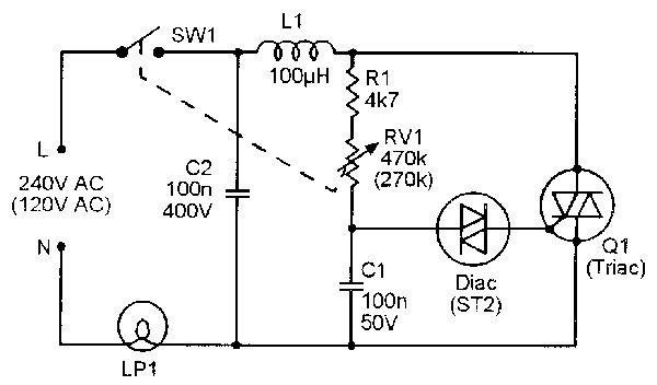
FIGURE 11. Practical circuit of a simple diac-type lamp dimmer with RFI suppression.
This circuit is really a simple variant of the basic lamp dimmer circuit shown in last month's Figure 6, with the addition of the L1-C2 RFI suppressor and with RV1 and SW1 ganged together to easily enable the lamp to be turned fully off.
A weakness of the simple Figure 11 design is that it has considerable control hysteresis or backlash, e.g., if the lamp is dimmed off by increasing the RV1 value to (say) 470k, it will not go on again until RV1 is reduced to about 400k, and then burns at a fairly high brightness level. This backlash is caused by the diac partially discharging C1 each time the triac fires. Backlash can be greatly reduced by using the 'gate slaving' technique in Figure 12, in which the diac is triggered from C2, which 'follows' the C1 phase-delay voltage but protects C1 from discharging when the diac fires.
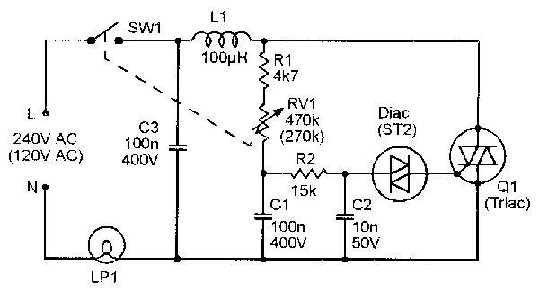
FIGURE 12. Improved diac-type lamp dimmer with gate slaving.
If desired, the backlash can be reduced to virtually zero by wiring a current-limiting resistor in series with the diac, to reduce the magnitude of the C2 discharge voltage, as shown in Figure 13.
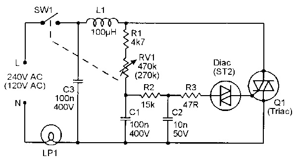
FIGURE 13. Minimum-backlash diac-type lamp dimmer.
A 'smart' lamp dimmer IC Many modern lamp dimmers have their triac driven via a dedicated 'smart' IC that can turn the lamp on or off or control its brilliance, the IC taking its action commands via a touch-sensitive pad or push-button input switch. For many years, Siemens was the leading producer of this type of IC, first with the IC known as the S566B, and then (starting in 1990) with the SLB0586, which remained in full production until 1995 (but was still widely available in early 2000). Today (in 2002), the most popular lamp dimmer IC is a low-cost Holtek product known as the HT7704B 'touch' dimmer.
The HT7704B is an eight-pin DIL IC with the outline and pin notations shown in Figure 14, and provides four levels of brightness plus switch-off control, all sequentially selectable via a simple metal 'touch' pad or plate that is AC coupled to pin 4 of the IC.
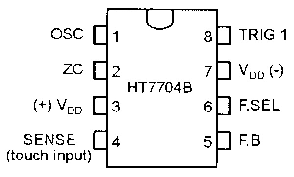
FIGURE 14. HT7704B outline and pin notations.
In use, the first 'touch' turns the lamp on at its lowest brighness level; the next three touches bring the brightness up to maximum level in successive stages; the fifth touch turns the lamp full off, and so on.
Figure 15 shows the basic application circuit of the HT7704B (without fused overload protection or RFI-suppression circuitry), with alternative component values and pin connections shown for use with 50Hz or 60Hz AC supplies with nominal values of 110V or 220V.
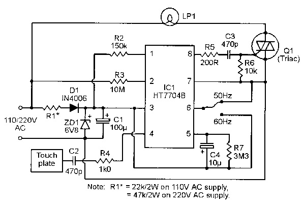
FIGURE 15. Basic HT7704B lamp dimmer application circuit.
Note that R1 is a 2W type and needs a value of 22K on 110V AC supplies or 47K on 220V AC supples, that pin 6 must be tied to pin 7 on 50Hz supplies or pin 3 on 60Hz supplies, and that the ratings of triac Q1 must be chosen to suit the lamp power and supply-voltage rating of the individual system.
Triac protection techniques
In use, triacs must always have an RMS current rating greater than that of the load that they are driving and must always be protected against catastrophic damage from current surges or malfunctions in their loads. Adequate protection can usually be obtained via a suitably-rated quick-blow fuse that is effectively connected (either directly or via a supply-connection plug) in series with the load and the triac's main terminals, but in a few special applications, additional protection may also be needed. Note that the fuse value must always be chosen with great care, and should be of the minimum practicable rating; a fuse with too high a rating provides no useful protection.
When a triac is used in an electric-heater driving circuit, a quick-blow fuse with a current rating greater than that of the heater but less than the maximum current rating of the triac provides adequate protection. When a triac is used in an electric-motor driving circuit, a quick-blow fuse with a current rating greater than the stalled current rating of the motor but less than the maximum current rating of the triac should be used.
In most filament-lamp driving triac circuits, the triac needs a current rating at least three times greater than the normal running current of the lamp, and should be protected by a quick-blow fuse with a rating of 500mA (1A absolute maximum) per 100W of lamp rating in 240V AC systems, or 1A (2A absolute maximum) per 100W of lamp rating in 120V AC systems; in some special filament-lamp driving circuits, however, additional protection may also be needed, as described later in this article. To understand the principles of triac protection in filament-lamp driving circuits, it is necessary to understand certain characteristics of fuses, filament lamps, and triacs as follows.
FUSE BASICS. An ordinary 'quick-blow' fuse consists of a short length of wire, which burns out ('blows') if the current passing through it exceeds a limit determined by the wire's diameter. Most quick-blow fuses use a copper wire, which has a melting temperature of 1083°C and a resistance that — when referenced to 20°C — increases by about 0.4% per °C increase in temperature. Thus, when the current passed through the fuse exceeds roughly 40% of its rating, its resistance and power dissipation and temperature all increase exponentially with further increases in current, until a point is reached where the ability of the fuse to dissipate power is exceeded by the prevailing input power level; under this condition,the fuse eventually blows at its weakest point; when a fuse blows, its wire first melts at the failure point, which is then widened as current briefly arcs across the gap and vaporizes the adjacent metal.
All fuses carry a 'rating' figure (such as 500mA, 1A, 2A, 5A, etc.) which indicates the maximum current that the fuse can safely carry without blowing or suffering a reduction in its working life. The fuse will only blow if its rating figure is exceeded ('overloaded') for a significant period of time; thus, a 2A quick-blow fuse may take absolute maximum times of several days to blow at 2.2A, 2.5 hours at 3A, 1 second at 4A, 40mS at 6A, 8mS at 10A, 2mS at 20A, 500mS at 40A, and so on. All quick-blow fuses can thus safely handle large-amplitude current transients or surges, provided that they do not exceed a certain critical duration.
FILAMENT LAMP BASICS. An ordinary filament lamp consists of a tightly coiled Tungsten wire filament that is supported on insulated struts, has its two ends made externally available, and is enclosed in a sealed glass envelope or bulb. In use, an electric current passed through the resistive filament raises its temperature to a white heat, causing it to emit white light; the glass bulb that encloses it is normally filled by a non-reactive gas such as argon, to stop the filament burning up under this condition.
The Tungsten filament's wire has a melting temperature of 3370°C and a resistance that — when referenced to 20°C — increases by about 0.45% per °C increase in temperature, making the resistance value rise sharply with filament temperature. The resistance of a 240V 100W lamp is typically 40R at 20°C but is 576R under normal 'white heat' running conditions (the lamp thus shows about a 14:1 resistance variation over its full usage range). Note from this data that this 100W lamp consumes a normal RMS running current of 417mA from the 240V AC supply but — if it is initially switched on at a moment when the AC voltage happens to be at the peak point in a half-cycle — may pass an initial switch-on surge current of up to 8.46A, thus generating a 2030W switch-on power surge in the lamp. By comparison, a 120V 100W lamp consumes a normal RMS running current of 833mA and may pass an absolute peak switch-on surge current of 16.5A. In practice, the lamp's initial switch-on power surge makes its filament resistance rise very rapidly (in a few milliseconds) to a value reasonably near to the filament's normal operating value; the lamp-driving triac (and its protective fuse) must be able to handle this surge current without suffering damage.
Tungsten filament lamps have a typical operating life of about 2,000 hours. The outer surfaces of the coiled Tungsten filament slowly 'boil off' with continued use, until the weakened filament eventually blows at its most vulnerable (thinnest) point, in the same basic manner as in a fuse, i.e., the failure point first melts and is then partly vaporized by arcing; usually, the vaporized metal blackens part of the glass bulb's inside surface. Filament lamp failures occur in three basic types, which can be classified as 'simple,' 'recursive,' or 'catastrophic;' these failure types have the following characteristics. Most lamp failures are of the 'simple' type, in which the filament simply burns through and then arcs at its weakest point, vaporizing the local metal; the lamp emits an audible 'ting' as the two halves of the ruined filament spring apart; usually, the arcing debris blackens only the end of the bulb. This type of failure often occurs at the moment of initial switch-on and is usually harmless to triac drivers.
The 'recursive' type of lamp failure can be regarded as a small number of 'simple' failures occurring in quick succession. At the end of the first failure, the broken but still hot and vibrating ends of the filament briefly make contact and weld together, passing a surge of current through the remaining (but shortened) length of filament, which quickly suffers another failure at another weak point, and so on. In this type of failure, the lamp usually flickers on and off a few times before finally dying; the inside of the bulb normally becomes widely blackened as a result of the multiple arcing that occurs in this process. This type of failure may be accompanied by very heavy current surging, which may damage a driving triac that is not adequately rated or fuse-protected.
The 'catastrophic' type of lamp failure is a rare and very savage type of recursive failure, in which the internal arcing is so severe that the entire inner surface of the lamp and the filament's supports becomes coated in conductive vaporized metal, thus shorting out much of the filament and causing a very low resistance to appear across the lamp's terminals. This type of failure sometimes occurs in crude flashing-lamp disco displays in which the triac-driven lamps are switched on and off in response to the filtered amplitudes of the music, often going through thousands of on/off switching sequences (and their associated heavy surge currents) per hour; triacs need special protection in this type of application. In extreme cases of this type of failure, the triac may develop an internal short-circuit, and the fuse may then blow as the lamp filament self-destructs, thus destroying all three components during the 'failure' process.
TRIAC BASICS. From the 'current overload protection' point of view, the two most important parameters of a triac are its basic 'RMS on-state current rating,' IT(RMS), and its non-repetitive peak surge on-state current rating over a period of one full cycle duration, ITSM. Typically, ITSM is 10 times greater than IT(RMS) in 60Hz systems, and eight times greater than IT(RMS) in 50Hz systems. Thus, a 4A triac can typically handle ITSM surge current of up to 32A in a 50Hz system, or 40A in a 60Hz system.
TRIAC PROTECTION CIRCUITS. When all of the above data is put together, it transpires that the simplest on/off-switching or 'dimmer' type of lamp-driving triac circuit should take the basic form shown in Figure 16.
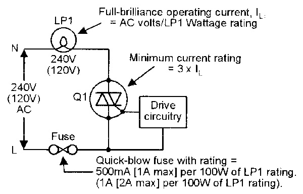
FIGURE 16. Basic triac and fuse selection data for use in simple on/off lamp switching and lamp dimmer types of application.
The lamp's normal 'fully on' running current, IL, equals the AC supply voltage divided by the lamp's power rating, the triac needs a minimum current rating of 3 x IL, and the fuse must be a quick-blow type with a current rating of 500mA (1A absolute maximum) per 100W of lamp rating in 240V AC system, or 1A (2A maximum) per 100W of lamp rating in 120V AC systems. Ideally, all modern lamp-driving 'on-off' types of triac circuit (including those used in flashing-lamp disco displays) should take the basic form shown in Figure 17, in which the main triac is gated via an optocoupled synchronous 'zero-voltage' triac (as described earlier in this article), thus completely eliminating all switch-on surge current problems.

FIGURE 17. Ideally, all on/off-type lamp switching circuits should be gated via an optocoupled synchronous 'zero-voltage' triac, to eliminate all switch-on surge current problems.
In very extreme cases, particularly in flashing-lamp disco displays, the above circuit can be modified to give the main triac additional protection against damage from the 'catastrophic' type of lamp failure by wiring a ballast resistor is series with the load, as shown in Figure 18; this resistor must be a wire-wound type with a resistance equal to at least 5% of the lamp's hot resistance and with a power rating equal to at least the same percentage of the lamp's power rating.
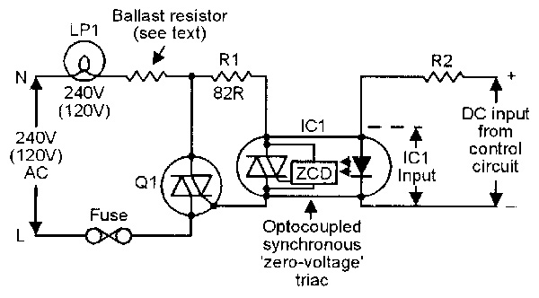
FIGURE 18. In extreme cases, such as in flashing-lamp disco displays, the main triac (Q1) can be protected against damage from a 'catastrophic' lamp failure by a ballast resistor, wired as shown.
If the lamp suffers a near-short-circuit during a catastrophic failure, this ballast resistor limits the surge current to a value that blows the fuse but does not damage the triac; the ballast resistor gives a slight reduction in lamp brilliance under normal running conditions. NV