For many years, I have enjoyed learning about various aspects of our universe such as electricity, computer systems, and physics. I truly believe that there is no better forum for playing with these things than ham radio. In the last couple of decades, I have had the privilege of working with various junior engineers who labored with me and learned many of the things that I once sought to absorb. I have met engineers who “just got it” and others who struggled due to incorrect preconceptions. For me, the most fundamental among these struggles was a real usable understanding of Ohm's Law.
Most (if not all) of us have seen the formulas. They’re relatively simple, and many of us can easily use rudimentary high school algebra to calculate two values from any other two by just manipulating the formulas. For example, if we know voltage and resistance, we can calculate current and power. However, just because we can “work the math” does not mean that we really understand Ohm’s Law well enough to make it work for us.
To get electrical charges to do our bidding, we need to understand when and how to apply and combine the formulas. We may also need to let go of some concepts that we currently have.
Figure 1 is well worn. The values may differ, but the diagram is used frequently to begin work with the Ohm’s Law equations.
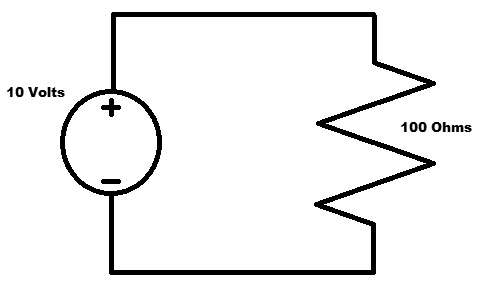
FIGURE 1. A well worn circuit.
We see that we have a voltage source and the voltage is placed across the resistor whose resistance is known. One thing that I have never heard clearly pointed out is that voltage appears (is measured) across things, while current (electrical charge flow) is measured through things. Like power and energy, many people (even some not so novice) confuse voltage and current, and especially what they do.
Voltage is a difference between the electrical potential of two separate places. Science class calls it electrical pressure or electromotive force. There is a fairly extensive analogy to water and pressure and flow that sometimes helps people understand electricity.
With water or air pressure, we can’t talk about the pressure at some place. Pressure must be a difference between two places. Sometimes we see a pressure gauge that simply indicates, for example, PSI (Pounds per Square Inch) pressure. Unless it is labeled with (for example) an extra letter such as PSIA (Pounds per Square Inch Absolute), we are put upon to assume that PSI is with respect to the environment around the meter. There still needs to be a pressure difference to push the needle up.
As with pressure, one can NEVER have a voltage at a point. A question like “What is the voltage at that terminal?” becomes nonsense unless there is an agreed upon “other place.” Frequently, that place is assumed to be ground (like the dirt outside your shack or the body of your car). In those cases, you will hear people talk about voltage at a point. However, it must always be in the back of your head that the voltage is with respect to some other point, and that point MUST be agreed upon by all involved in the conversation.
In Figure 2,
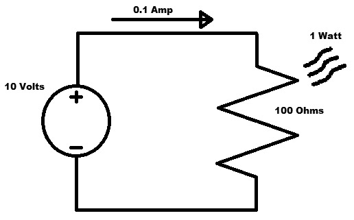
FIGURE 2. Some values determined.
we have used Ohm’s Law to fill in the unknown values:
I = V / R = 10/100 = 0.1 Amp
Power = V x A = 10 x 0.1 = 1 Watt
The current goes through the resistor and then around and back through the voltage source. The resistor — because it has resistance — will have a voltage across its terminals caused by the current that flows through it. The combination of current through the device and voltage across the device causes power to be processed by the device and turned to heat.
Keep these points in mind:
- Voltage is always measured across something.
- Current is always measured through something.
- Resistance is a characteristic of something.
- Power is the result of a voltage across something AND a current through that thing.
It’s important to realize that the wires connecting the resistor to the voltage source have the same current going through them as the resistor. The current goes all the way around this simple loop. However, the wires have very little resistance (in this ideal case, we may assume that they have no resistance). Because the wires have no resistance, they cannot use power from the current going through.
That is how electricity “knows” to heat up the filament in the incandescent light in your lamp but not heat the wires, switch, and connectors. For power to be used, we need both voltage across something and current through that same thing. One or the other doesn’t provide power. That is, voltage without current or current without voltage will not generate power. Open a circuit and no power will be used in what used to be a circuit.
The Trick Question
In Figure 3, we have broken the circuit at the top.
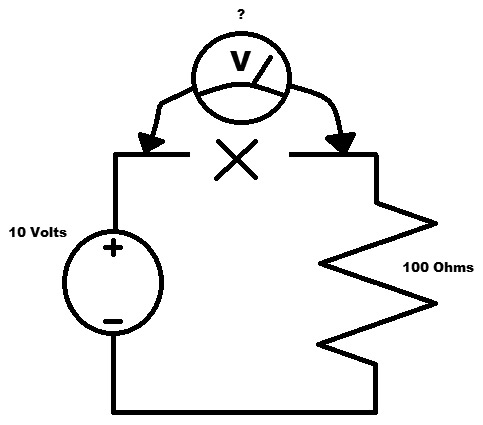
FIGURE 3. The question.
This is where we had 0.1 amps of current just before the break. The trick question is: “With the voltmeter leads across the break, what does the meter read?”
Hint: A good quality voltmeter will have a very high impedance. It will draw very little current when operating to minimize the effect that it has on the voltage being measured. In our case, the voltmeter is perfect and has an infinite impedance. Nary a charge shall pass; that is, current is zero.
Trains of Thought
If you are already sure of the answer, then this article is not for you. Some engineers and technicians will recognize immediately what is going on here. If you’re the least bit unsure, bear with me. This may be of some value.
Train A
“There is no current, so there must be no voltage. The meter would read zero.”
This train doesn’t get you there. This is the most common rationale that I have seen for this presentation. The problem is that its premise is false. We can have voltage with no current. It’s called static electricity. Static electricity is electricity with no charge flow. Although batteries will have a small current flow and eventually self-discharge, you can buy a package of alkaline batteries that are a year old and still use them to provide a power source until they are depleted. Voltage can be present on the batteries without current flow all the time they are in the package.
Train B
“The meter completes the circuit, but I don’t know what the current would be.”
This train doesn’t get you there either. If the meter has an infinite impedance, then it really doesn’t complete the circuit. In this “circuit,” there is zero current flow. It’s essentially not a circuit.
Train C
“The resistor is still in the circuit. It must drop some of the voltage. However, without knowing the meter resistance, we can’t know for sure what it reads.”
Again, this train doesn’t get you there. The meter has an infinite resistance; therefore, the current through it and the resistor is zero.
Train D
“The meter resistance is far higher than the 100 ohm resistor. All the voltage from the voltage source must drop across the meter. I say 10 volts.”
Train D gets you there. We can have voltage without current. The meter has a very high impedance (much higher than the 100 ohm resistor). All the current is blocked by the meter. The voltage across the meter must be 10 volts. The entire supply voltage is dropped across the meter.
Reality
We can get a better feel for why this is right by setting the trick question up as a voltage divider as shown in Figure 4.
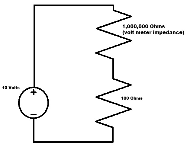
FIGURE 4. A more real circuit.
I also took the liberty of changing the meter impedance from infinite to a more real value. Here, we have a one million ohm resistor where the meter was placed. We can calculate the current that goes through both resistors by calculating the effective resistance. Since the 100 ohm resistor and the one million ohm resistor are in series, we can simply add them to determine what the effective resistance is to the circuit. The same current will flow through both resistors:
1,000,000 + 100 = 1,000,100 ohms
Note that this is still very near one million ohms.
The current would then be:
I = V / R = 10/1,000,100 = 0.000009999 amps
That’s pretty small. It’s a lot smaller than 0.1A we had before the “break.”
Since the same small current flows through both resistors, we can calculate how much voltage drops across each resistor AND how much power will be dissipated by each resistor. Yes, the meter will dissipate power, just hopefully very little:
V100 = I x R = 0.000009999 x 100 = 0.0009999 volts
Power100 = V x I = 0.000000009998 watts
The voltage across the 100 ohm resistor is now 0.0009999 volts. Not going to zap anybody here:
V1000000 = I x R = 9.999 volts
Power1000000 = I x R = 0.00009998 watts
The voltage across the one million ohm resistor is now 9.999 volts. So, because the meter impedance is so high, the voltage across it is essentially the voltage source. We can also see here that a high resistance can result in the higher voltage. Sounds weird but it’s true.
Also note that the total power used by both resistors is far less than that used by the single 100 ohm resistor in the original circuit. Resistance goes up, voltage goes up, but power goes way down. Again, weird but true.
In reality, no voltmeter has an infinite impedance input. However, most of them are pretty high. Even a relatively inexpensive meter (the kind that are sometimes given free by certain stores) may have an input impedance of a million ohms — far higher than most devices in circuits we use every day.
Just in case there are some non-believers, here are some photos of me performing the experiment to show what happens.
In Figure 5, I’ve constructed the circuit placing my cheap (free) multimeter across the break. In this case, I’ve gone to a 1,000 ohm (1K) resistor to prove a point. Even with 1,000 ohms in the circuit, the meter still reads essentially the power supply voltage.
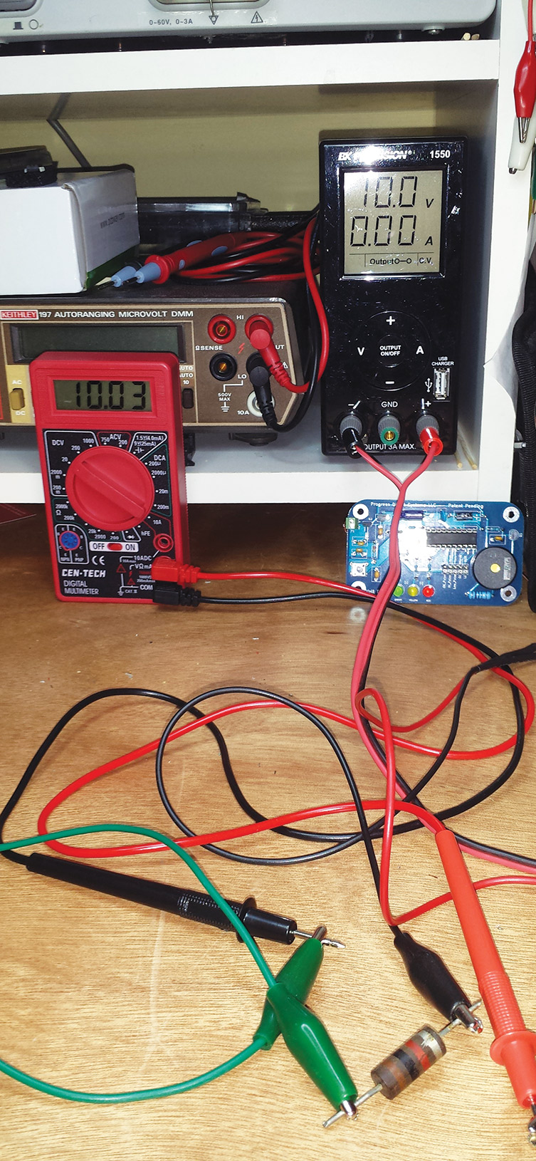
FIGURE 5. Measuring across a break with 1,000 ohms.
In Figure 6, I have replaced the 1,000 ohm resistor with one that is 10 times the value (10,000 ohms or 10K).
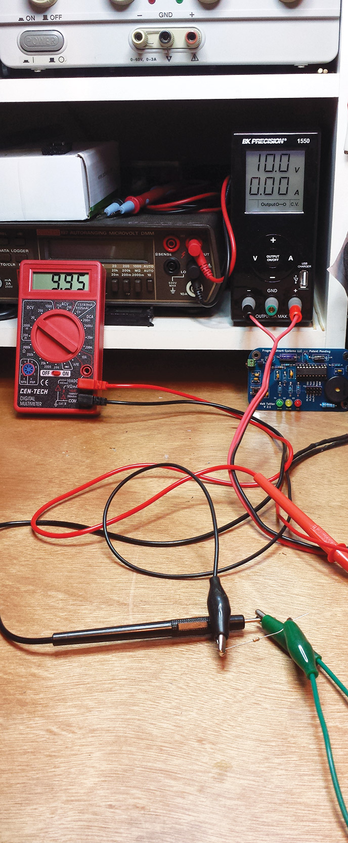
FIGURE 6. Measuring across a break with 10,000 ohms.
Here, we can still see that the bulk of the power supply voltage is dropping across the meter. It is, however, definitely a bit smaller, meaning that some voltage is dropping across the 10K resistor.
How about a million ohms?
At one million ohms (one megohm), we see a considerable drop (Figure 7).
FIGURE 7. Measuring across a break with a million ohms.
The voltage across the meter is now about half of the supply voltage. That means the other half of the voltage MUST be across the resistor.
What is very interesting about this combination is that the same current flows through the meter and through the resistor. They both have about the same voltage drop. This means that the meter must represent the same resistance as the resistor: one million ohms.
We have essentially measured the input impedance of this free digital multimeter. One million ohms is pretty good for most troubleshooting. Some better quality meters will have a 10 million ohm input impedance. Some expensive meters are even higher.
Last Trick
There are many other “trick” questions that I have used to stimulate thinking about Ohm’s Law. It took me a long time to figure these kinds of things out. Hopefully, this will make that transition easier for you. NV
During troubleshooting, if two devices are in series, we can sometimes tell the one that is bad by simply measuring the voltage across them. If the voltage is all across one device, then it must be preventing current and is possibly the bad device.
Incandescent light bulbs frequently go open-circuit when they blow. If the supply voltage is measured across the bulb, it's probably bad.
Got Two, Get Two Free
With Ohm's Law and the Power Equation, we have two formulas that provide an insignt as to what is happening with electrical systems — at least DC electrical systems.
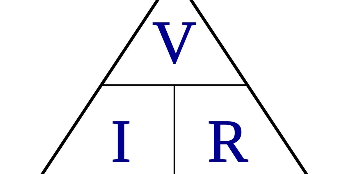
Ohm's Law can be expressed in three ways:
V = I x R, I = V/R, and R = V/I
where V = voltage, R = resistance, and I = current.
If we know any algebra, we can see that each of these equations can give us the other two simply by solving for the value that we do not have.
The Power Equation is:
P = V x I
Wherever there is both voltage and current, there will be power going somewhere.
Using these two equations, we can get any two values given the other two. For example, assume that we know the voltage across and resistance of a device. The device may be anything. Knowing these two values, we can determine the other two:
I = V/R
Placing the voltage value for V and the resistance value for R, we have determined I (the current).
Knowing both the current and voltage, we can determine the power dissipated by the “thing:”
P = V x I, = V x V/R = SQR(V)/R
Learn at least a bit of algebra. Then, these equations become less memorization and better understood.