The Applications are Limitless
This universal relay board will allow you to drive a 12-volt DPDT relay using heat, cold, light, dark, sound, logic-level voltages, and just about any varying resistive output sensor you can think of. In fact, you can use it to switch the relay ON or OFF using any voltage between zero to 12 volts DC or any sensor that has a varying output in this range. This is the ultimate relay board. It could even be made to run on six or 24 volts DC with a few resistor changes and the availability of the appropriate voltage relay.
I set out to design this project with simplicity in mind; I wanted to keep the component count to a minimum and to use the same value components for all configurations available. Size was also a factor — the smaller, the better. There are heaps of similar individual circuits around in kit form, in books, or on the internet, but none that integrates everything and allows the user the flexibility that this circuit does with a minimum of fuss.
First things first: Decide how you will configure the relay (e.g., heat, cold, sound or five-volt logic, light or dark). Then decide if you want to trigger the relay ON or OFF (e.g., hotter — on, hotter — off). See the configuration details below to help you make your choice.
Basically, we need a resistive-type sensor with an opposing fixed resistor to form a varying-input voltage divider or a sensor, etc., that has a varying voltage output.
Some Available Sensors
Thermistor NTC
The negative temperature coefficient (NTC) thermistor I have chosen is the 100K Ω type, which means that at 77 degrees F (25 degrees C) it has a resistance of 100K Ω. The resistance of the NTC type falls as it heats up, and the most common types can be used to measure temperatures from below 32 degrees F (zero degrees C) to just above water’s boiling point at 212 degrees F (100 degrees C), depending on the type of NTC available. They are available with 10 and 47K Ω resistance as most common, but other values are available, as well. There are also positive temperature coefficient (PTC) thermistors manufactured with opposite abilities, though not generally as common.
LDRs
Light dependent resistors (LDR) rely on light to change their resistance. Typical resistances for darkness could be 500K Ω to many megohms that decrease to a few thousand ohms in bright light. Some may even go as low as a few tens or hundreds of ohms, depending on the manufacturer and quality.
Both the thermistors and LDRs have a maximum current rating, and if, for example, a very bright light or hot temperatures are encountered, the resistance of the device may approach zero ohms. In this case, make sure opposing resistors used do not allow the device’s maximum current rating to be exceeded. It is a good idea to try to match the opposing resistor to the device used.
For a 100 kilohm NTC thermistor, use a 100 kilohm resistor, or, if you need to have an LDR sense the difference in very low levels of light, you may like to try a 500 kilohm or a one megohm resistor. This will keep the range you wish to cover in the center position of the VR1 pot. A minimum of one kilohm for an opposing resistor will keep the maximum allowable current to 12 mA. This should be enough to cover any unusual situations. The VR1 pot may be in full lock, though, so try to balance the resistances to a 50/50 ratio within your application.
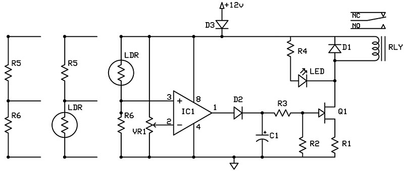
FIGURE 1. For the optional LDR shown to the left, try a 500K Ω resistor (R5).
Circuit Description
The circuit was designed to run on 12 volts DC, but could be made to run on six or 24 volts with a few resistor changes, depending on relay availability. The LM358 low-power, dual-operational amplifier chosen can run from a single supply voltage, as opposed to split supply, e.g., ±12 volts. The LM358 has an output swing of almost full rail to rail; here it is 12 volts positive to zero volts negative. Only half of the LM358 is used here for all configurations.
The op-amp is set up as a non-inverting comparator in any of the configurations. This means that it will toggle the output of the LM358 high whenever the inverting, negative input, Pin 2, is more negative than the voltage at its positive input, Pin 3. Otherwise, it will toggle the output low when vice-versa input voltages are applied. Via VR1, the negative input can be set to sense any voltage from rail to rail and positive to negative (except in the sound-activated configuration which is highly biased toward the negative rail). The transition between high and low output on the LM358 only needs one of the inputs to be around five millivolts higher or lower, which is very sensitive. The output of the microphone is around 100 millivolts at its maximum output.
The output of the LM358 passes through D2 IN4148, then charges up C1 (a 1 µF electrolytic capacitor), which acts as a one second sample and hold. It can’t discharge back through D2, but only through R3 by increasing the value of C1 to about 47 µF. As a result, you will get a very long latching effect, close to one minute in length.
Originally, I thought a junction field-effect transistor (JFET) might be able to drive the relay, but instead I found a much better option, the 2N7000. Therefore, R1 was left onboard. The reason for this is that field-effect transistors (FET) draw very little current to switch fully; they rely mainly on the voltage on their gates to work. Usually, JFETs need a negative voltage on their gates to turn off fully (below the actual zero or negative rail), but the 2N7000 metal-oxide semiconductor field-effect transistors (MOSFET) are much easier to use. Most JFETs don’t have enough drive capability for a relay anyway.
The 2N7000 does not need the negative gate bias. It is actually an N-channel enhancement mode MOSFET. A bi-polar transistor is unsuitable in this circuit (mainly for the microphone version), as it needs too much base input current to operate correctly, but a FET that only needs voltage works fine.
This particular FET can handle up to +30 volts on its gate input, but it can’t have any current driving it. More than a few milliamps will kill these devices very quickly.
The R1 serves several purposes. To save power, it reduces the current drawn by the relay, which may be an advantage if a battery supply is used. Also, it can be used to run the circuit a few volts above the relay voltage if needed. R1 could be replaced with a wire link. The voltage drop across R1 does not affect the relay (it could be replaced with a wire link), while a 200 ohm resistor would be enough to stop the relay from fully energizing.
Other TO-92 Package MOSFET Devices that may work are the following:
- Vishay, TP0610L/VP0610L/BS250, I/DS around 180 mA.
- VN0300L, I/DS around 200 mA.
- Fairchild BS170, I/DS around 500 mA.
Check for correct pinouts before using other devices. These devices can be damaged by static electricity; take care.
If an LM358 op-amp is not available, you could try one of the many dual eight-pin op-amps, as long as it can run on a single supply voltage and has a reasonable O/P voltage swing. Just check the spec sheet on any other device you decide to use, as many of these dual op-amps are pin-for-pin compatible.

FIGURE 2. The mic’s FET needs to be powered via R5, a 22K Ω resistor.
Which Sensor to Use ... Have You Decided Yet?
Electret Microphone
The Electret microphone has a small FET inside it that needs to be powered. This is supplied via R5, a 22 kilohm resistor. When sound is detected by the microphones element (a tiny capacitive-plate-charged disk inside), the built-in FET amplifies the tiny signal and it is modulated against the supply voltage from R5. Capacitor C2 (0.22 µF) picks up this tiny modulated voltage and passes it to the LM358’s non-inverting positive input.
The sound-activated section has very little output swing, so R7 is used to tie the non-inverting input very loosely low to prevent the LM358 from toggling when no input signal is present (but with minimal loading on C2).
Using sound as the triggering source for the op-amp has some drawbacks because it is not very constant. In reality, the positive input detects the audio peaks, which can move in the kHz range and is not good for switching any relay on or off. Hence, C1 is used. Also, because the incoming microphone voltage has a very small swing, R8 (at one megohm) is used to effectively stretch the voltage scale in the window that the negative, inverting input of the LM358 is referencing.
D1 prevents reverse voltage when the relay disengages from destroying the FET. The LED has a 1.2 kilohm current-dropping resistor.
To select the LDR input for decreasing light,,, to toggle "ON"
Or the Thermistor to sense less heat,,,, to toggle "ON" use.
The opposing resistor is tied to high, positive, and the sensor is tied to low, negative. Here on R5, a 100 kilohm resister is used. R6, C2, and R8 are wire links, and the dotted line under C2 is not used here. R7 is omitted.
To select the LDR input for increasing light,,, to toggle "ON"
Or the Thermistor to sense more heat,,,, to toggle "ON" use.
The opposing resistor is tied to Low, -Neg and the Sensor is tied to Hi, +Pos. Here, R5 is a link R6 100K is used or see text and C2 is omitted, R8 is also a wire link and the dotted line under C2 is used here as a wire link, R7 omitted.
The microphone input, R5 (at 22K Ω) and R6, is a wire link. The dotted link under C2 (0.22 µF) is not used, and R8 is one megohm. For R7, 10 megohms is only used here.
To use five-volt logic to turn on the relay, attach a 10 kilohm resistor to -R6 and a 100 kilohm resistor to +R5. The junction of these should produce just over one volt to ground, which will hold the positive input of the IC1 logic low until the five-volt logic arrives. If you need a higher impedance, try a ratio of 100K Ω/1M Ω. To use an inverted logic voltage, just swap the high and low resistors or try R5 = 56K Ω, R6 = 39K Ω. This will hold the LM358 non-inverting, positive input high until the logic low arrives. Now, use a wire link instead of C2 and make (also) the dotted line below it, R8, a wire link. Both input terminals now become the positive input signal. You’ll need a ground point for this input, and there is a spare pad available just below R6. R7 is omitted. Adjust VR1 to set the exact voltage level needed. (Both of the usual input terminals become linked to provide a junction point for R5 and R6.) Both C2 and the dotted line under it need to be wire links here.
Using the Voltage Divider Option as the Input
To activate the relay using any input voltage from zero to 12 volts (user defined), select the input voltage to be just above for ON or just below for OFF. R5 and R6 then hold the positive input of the LM358 slightly higher or lower than the incoming, user-defined input-voltage signal, allowing the relay to toggle on or off when it does. Fine tune this using VR1, which may end up being very offset the closer you get to the positive or negative supply rails.
This table is for R5 and R6 at 12 volts DC.
High Side + Low Side - Voltage = the value at the resistor’s junction to the zero-to-negative rail.
R5 = 10K Ω R6 = 100K Ω Voltage = 10.9 V - 11.0 V & above = ON, 10.8 V & below = OFF
R5 = 15K Ω R6 = 82K Ω Voltage = 10.1 V - 10.2 V & above = ON, 10.0 V & below = OFF
R5 = 22K Ω R6 = 68K Ω Voltage = 9.0 V - 9.1 V & above = ON, 8.9 V & below = OFF
R5 = 33K Ω R6 = 56K Ω Voltage = 7.5 V - 7.6 V & above = ON, 7.4 V & below = OFF
R5 = 39K Ω R6 = 47K Ω Voltage = 6.5 V - 6.6 V & above = ON, 6.4 V & below = OFF
R5 = 47K Ω R6 = 47K Ω Voltage = 6.0 V - 6.1 V & above = ON, 5.9 V & below = OFF
R5 = 56K Ω R6 = 39K Ω Voltage = 4.9 V - 5.0 V & above = ON, 4.8 V & below = OFF
R5 = 68K Ω R6 = 33K Ω Voltage = 3.9 V - 4.0 V & above = ON, 3.8 V & below = OFF
R5 = 82K Ω R6 = 22K Ω Voltage = 2.5 V - 2.6 V & above = ON, 2.4 V & below = OFF
R5 = 100K Ω R6 = 10K Ω Voltage = 1.09 V - 1.19 V & above = ON, 0.99 V & below = OFF
For a higher impedance input, use the same ratio of resistance, but multiply x 10; e.g., for 10.1V R5 = 150K Ω, R6 = 820K Ω.
The higher the overall resistance, the less supply power consumed.
These are only a few of the available voltages; by using the E24 range of resistors, many more are available. Experiment!
Voltage Divider Definition:
Two resistors in series connected across a voltage source. The voltage at the common junction is a fraction of the total applied voltage, determined by the resistor values.
eg: Pos Neg = < side connected to
10K Ω + 10K Ω = 1/2-supply voltage
2K Ω + 8K Ω = 3/4-supply voltage
8K Ω + 2K Ω = 1/4-supply voltage
All are measured between the junction and the Neg/Zero supply rail. You can have more than two resistors. Three resistors, for example will produce a window voltage; eg., 20 volts supply, 10K Ω + 5K Ω + 10K Ω will produce “four volts” across the five kilohm resistor — 2/5 + “1/5” + 2/5 of the total supply. But this voltage has no direct reference to either supply rail, as it is floating somewhere in between.
Voltage Cut Out/In Setup
Here, a zener diode and resistor take the place of R5 and R6. To use the relay as a low-voltage cut out/in for a 12 volt car, NiCad, NmHi, or other battery, you will need a zener diode and a resistor — one to 10 kilohm — as the value isn’t critical. The zener needs to be at least a volt or so lower than the cut out/in voltage you want to use.
Low voltage cut out
Setting: zener to positive, reversed biased, of course, resistor to negative. Drop the total supply to the voltage needed and set VR1 just OFF. Restore full supply voltage, when the supply is reduced to the cut-out voltage, the relay will go OFF.
High voltage cut off
Setting: zener to negative, still reversed biased, resistor to positive. Raise the total supply to the voltage needed; set VR1 just OFF. Lower the supply voltage. When supply is raised to the cut-out voltage, the relay will go OFF. Here, C2 is a link and the dotted line below it, R8, is a link. R7 is omitted, and the input terminals are not used here.
Note this configuration will only work for voltages around ±3 volts at 12 volts and around ±2 volts at six volts, where you will need a six-volt relay. The circuit has to have enough voltage to activate the correct voltage relay, but not so much as to cook the relay. Try bypassing R1 if you’re under the relay voltage or leaving it in place if just over the relay voltage.
Now, because the supply voltage is not constant in both the above instances and the zener is, the zener becomes the only constant in the circuit. The circuit is virtually flipped upside down with the zener becoming the reference and the rest of the circuit becoming the varying input. That’s the easy explanation!
Assembly
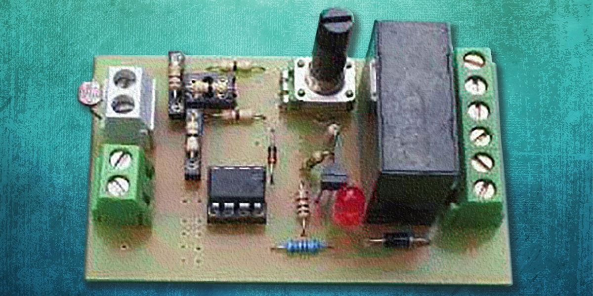
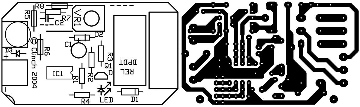
The assembly should be fairly straightforward, as there are not that many components. Take the usual precautions to check component polarity and orientation. A protection diode, D3 1N4004, was added at the last minute; it could be bypassed/bridged, if you like. There are microphone mounting pads beside each input screw terminal pad, but you might like to use fine wire to mount the microphone until you work out the sensitivity you need. If you need maximum sensitivity, mount the mic off the printed circuit board to prevent the relay vibration from false triggering itself. If a nine mm pot is unavailable, use a five mm trimmer pot.
Testing the Sound Activated Section
All testing should be done with C1 (1 µF) omitted; this will make it easier to see what’s going on, as VR1 set to about three-quarter-clockwise position should give maximum sensitivity. Rotating it clockwise a little bit will fully toggle on the LM358 output, while rotating counterclockwise will give a gradual gain reduction due to R8. Without it you would get a drastic gain reduction that would instantly snap OFF.
Once IC1 goes briefly high, C1 holds this voltage for a second or so, preventing the relay from trying to switch at audio frequencies. C1 also helps smooth out any relay chatter that can occur when using an LDR at the transition point; an incandescent light source can cause this.
When setting up the microphone version particularly near the very maximum sensitivity end of the scale, move VR1 slowly and allow a second or so for the circuit to settle for best results. The sound activated relay version was not designed to activate with constant low-level speech, as this would make the circuit unusable in a practical sense (it would be constantly going on or off). The circuit needs a slight audio peak to trigger. The best response is from percussion-type sounds mostly — clicks, pops, thumps, etc. In some cases, the relay clicking on and off may re-trigger itself. Vibration travels fairly well through a circuit board; I have had the relay coil singing to the microphone in a feedback loop. The sensitivity of the circuit may be increased slightly by mounting the microphone off the circuit board.
If you need to have the sensor or microphone some distance away from the circuit board, you should use shielded wire to avoid any noise induced into the cable. The pad below R6 can be used for the shield wire in this case.
Testing the LDR/Thermistor Activated Section
As mentioned earlier, try to get a balanced resistor/sensor resistance. This will give you a better ± rotation (midway) on VR1 for fine-tuning later. As a starting point, you may like to measure the resistance of the LDR or thermistor at the temperature or light level you want the relay to activate at, then pick a resistor that is close to this value.
If you happen to end up with a very low resistance on your sensor, you can cheat a little by adding a oneto 10 kilohm resistor in series with the sensor, but also add an equal value to the fixed resistor. Try some experimenting with resistor values; you can get quite creative and produce very wide or narrow windows for temperature sensitivity, etc. Just remember sensor current ratings, though. Remember to maintain a 50/50 sensor/resistor ratio for better ±VR1 rotation.
Don’t forget to replace C1 after setup.
Some Examples of Thermistor Resistance/Temperature Resistances.
10K Ω Thermistor was used here.
69K Ω = 14ºF or -10ºC
37K Ω = 32ºF or 0.0ºC — Freezing point of water.
21K Ω = 50ºF or 10ºC
13K Ω = 68ºF or 20ºC
10K Ω = 77ºF or 25ºC — Rating (10K Ω NTC) is taken from here at 25 degrees C.
7.8K Ω = 86ºF or 30ºC
5.0K Ω = 104ºF or 40ºC — Try to match the opposing resistor to the sensors
3.3K Ω = 122ºF or 50ºC resistance value at the temperature or light level.
2.2K Ω = 140ºF or 60ºC This gives a better ± pot rotation.
590 Ω = 212ºF or 100ºC — Boiling point of water = 20 mA current flow at 12V.
If you're interested, the relay can be made to self-latch by taking the spare pad between the relay and VR1 and connecting it to one of the relays’ normally open (NO) terminals. Linking pads are provided onboard. The matching “C” common terminal is then taken to the Neg supply rail. By doing this, you effectively bypass the FET Q1 after it has initially engaged the relay. You need to insert a switch in this connection to break the circuit to release the relay and reset it.
The current rating of the left-hand set of relay contacts is only rated at around two amps due to the circuit board track width. The circuit draws just under one mA at 12 volts on standby, 45 mA with the relay and LED on, and about 62 mA if you use the latching option when the FET is bypassed. NV
Note: For best results, use a regulated power supply, with microphone option especially.
The Applications are Limitless, So Get Your Imaginations Into Gear and Have a Go!
Possible uses could include:
- Battery protection for cars, low voltage accessory cutout
- Battery charger (NmHi, NiCad, SLA) cutout/warning, heat monitoring, overvoltage
- Baby monitor using microphone input
- Garden light controller, sunset activation
- Aquarium/incubator heater control or failure warning
- Power failure warning (battery backup supply needed), use voltage divider input
- Fire warning, connected to security system
- Intruder sensor, use LDR/LED beam, etc., in a security system
- Hand clap activated switch, breaking glass sensor in a security system
- Peltier device control, fridge, or incubator
- Garage door opener (LDR in a tube), set to activate with car high beam lights
- Voice-activated switch for an intercom, CB radio, transmitter, etc.
- Computer automation of other devices using logic voltages
- Toxic gas detection using a metal oxide range of gas detection sensors
PARTS LIST
| R1 |
100 Ω, see text |
| R2 |
1M Ω |
| R3 |
33K Ω |
| R4 |
1.2K Ω |
| R5 |
22K Ω mic only or 100K Ω, see text |
| R6 |
100K Ω or link, see text |
| R7 |
10M Ω sound option only |
| R8 |
1M Ω or wire link for thermistor/LDR/voltage |
| VR1 |
100K Ω 9 mm pot or 5 mm trimmer linear |
| Thermistor |
100K Ω NTC or see text |
| LDR |
ORP12 or equiv. |
| C1 |
1 µF electrolytic, see text |
| C2 |
0.22 µF monolithic, mic input only |
| D1 D3 |
1N4004 |
| D2 |
1N4148 |
| Q1 |
2N7000 N-channel MOSFET or equivalent |
| IC1 |
LM358 op-amp |
| LED |
Color, your choice |
| Mic |
Electret microphone, two-wire |
| REL |
DPDT 12V DC relay or 5V, 6V, 24V DC if available |
| Terminals |
PCB mount screw terminals, 1x6 or 2x2 for professional looking job. |
| PCB |
Artwork available in downloads section |
To fit the project in a small box, a low-profile relay is needed; they are available at slightly higher cost. You may also need to do a small amount of filing near the PCB mounting holes to clear the internal lid mounting pillars of the box. The VR1 pot needs a small hole drilled in the lid to protrude through or cut its shaft down slightly, but be careful. You may also want a hole for the LED.
If you’re using an IC socket, please use a machined pin type. Six and 24 volt relays are also available; with a few resistor changes, you could run the board at five, six, or 24 volts DC.
The components are commonly available at the usual electronic suppliers.
Downloads
Parts placement diagram
PCB layout