Invariably, video information must be transferred from one device to another. It could be from a satellite set-top box or DVD player to a television — or it could be from one chip to another inside the satellite set-top box or television. Although it seems simple, there are many different requirements and, therefore, many different ways of doing it.
Until a few years ago, most consumer video equipment supported only analog video. Digital video was confined to professional applications, such as video editing.
The average consumer now uses digital video every day, thanks to continually falling costs. This trend has led to the development of DVD players and recorders, digital set-top boxes, digital television (DTV), portable video players, and the ability to use the Internet for streaming video data.
Video Data
Initially, video contained only Y or grayscale (also called black-and-white) information.
While color broadcasts were being developed, attempts were made to transmit color video using analog RGB (Red, Green, Blue) data. However, this technique occupied 3x more bandwidth than the current grayscale solution, so alternate methods were developed that led to using Y, U, and V data to represent color information. A technique was then developed to transmit this Y, U, and V information using one signal — instead of three separate ones — in the same bandwidth as the original grayscale video signal. The general relationship between YUV and gamma-corrected RGB (R´G´B´) is:
Y = 0.299R´ + 0.587G´ + 0.114B´<br />
U = – 0.147R´ – 0.289G´ + 0.436B´<br />
 = 0.492 (B´ – Y)<br />
V = 0.615R´ – 0.515G´ – 0.100B´<br />
= 0.877(R´ – Y)
R´ = Y + 1.140V<br />
G´ = Y – 0.395U – 0.581V<br />
B´ = Y + 2.032U
In order to transmit the color information so that black-and-white televisions would still display the grayscale image, the color information (U and V) is modulated onto a 3.58 MHz (NTSC) or 4.43 MHz (PAL) subcarrier and added to the grayscale video signal.
composite color video = Y + U sin wt + V cos wt + timing<br />
w = 2pFsc<br />
Fsc = ~3.58 MHz for NTSC; ~4.44 MHz for PAL
The resulting NTSC composite video signal (Figure 1) is what the NTSC, PAL, and SECAM video standards are still based on today.
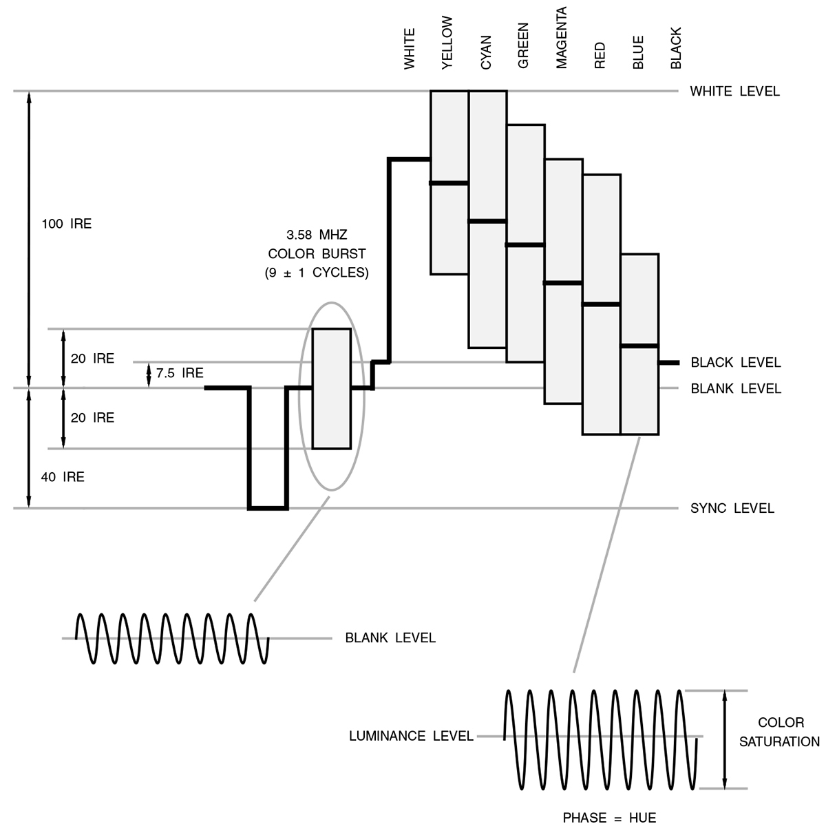
FIGURE 1. NTSC composite video signal for 75% color bars.
S-video was later developed for connecting consumer equipment together (it is not used for broadcast purposes). It is a set of two analog signals — the grayscale (Y) signal (shown in Figure 2) and the chroma (C) signal that carries the U and V color information in a specific format (shown in Figure 3).
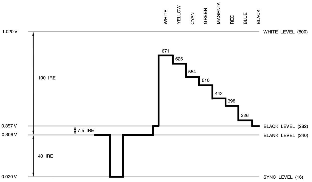
FIGURE 2. NTSC luminance (Y) video signal for 75% color bars. Indicated luminance levels are 10-bit values.
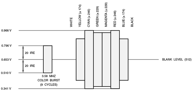
FIGURE 3. (M) NTSC chrominance (C) video signal for 75% color bars. Indicated video levels are 10-bit values.
Note that if Y and C are added together, the result is a composite video signal. Once available only for S-VHS, S-video is now supported on most consumer video products.
Although always used by the professional video market, analog RGB video data has made a temporary come-back for connecting high end consumer equipment together. Like S-video, it is not used for broadcast purposes.
A variation of the analog YUV video signals called YPbPr — illustrated in Figure 4 — is now commonly used for connecting consumer video products together. Its primary advantage is the ability to transfer high definition video between consumer products. Some manufacturers also label these YPbPr connectors as YUV, YCbCr, or Y(B-Y)(R-Y).
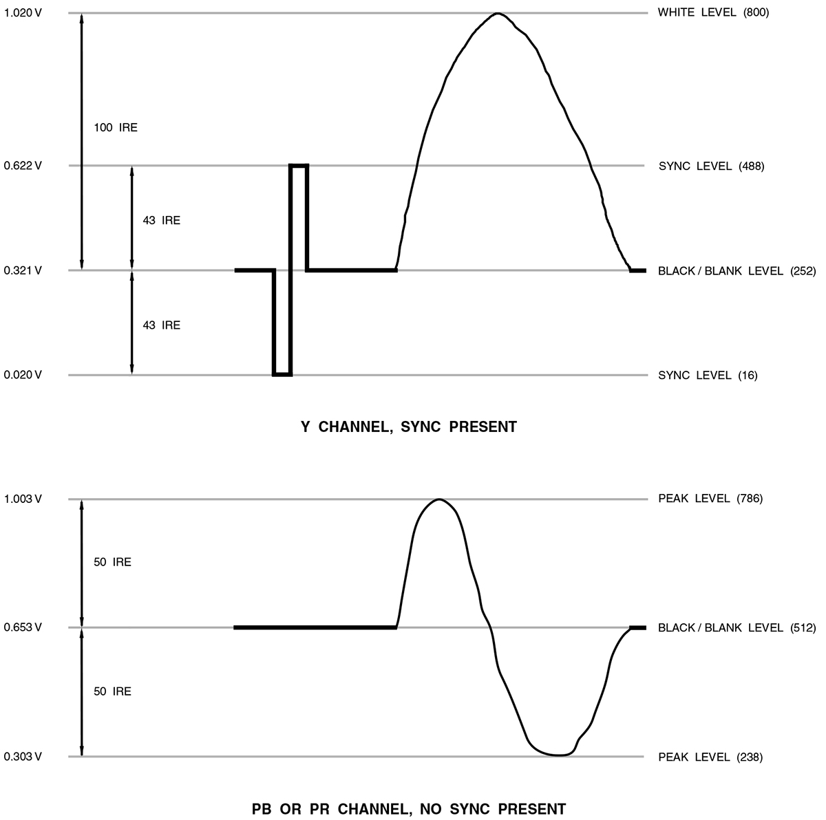
FIGURE 4. HDTV analog YPbPr video signal.
Video Timing
Although it looks like video is in continuous motion, it is actually a series of still images, changing fast enough that it looks like continuous motion, as shown in Figure 5.
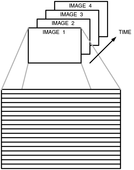
FIGURE 5. Video is composed of a series of still images. Each image is composed of individual lines of data.
This typically occurs 50 or 60 times per second for consumer video and 60–90 times per second for computer displays. Special timing information known as vertical sync is used to indicate when a new image is starting.
Each still image is also composed of scan lines — lines of data that occur sequentially, one after another, down the display, as shown in Figure 6.
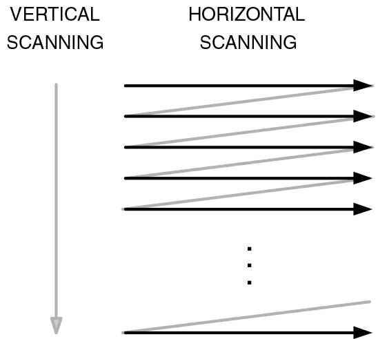
FIGURE 6. Progressive displays “paint” the lines of an image consecutively, one after another.
Additional timing information — horizontal sync — is used to indicate when a new scan line is starting. The vertical and horizontal sync information is usually transferred in one of three ways:
- Separate horizontal and vertical sync signals
- Separate composite sync signal
- Composite sync signal embedded within the video signal
The composite sync signal is a combination of both vertical and horizontal sync. Computer and consumer equipment that uses analog RGB video usually uses technique 1 or 2. Consumer equipment that supports composite video or analog YPbPr video usually uses technique 3. For digital video, either technique 1 is commonly used or timing code words are embedded within the digital video stream.
Interlaced vs. Progressive
Since video is a series of still images, it makes sense to simply display each full image consecutively, one after the another. This is the basic technique of progressive — or non-interlaced — displays. For progressive displays that “paint” an image on the screen (such as a CRT), each image is displayed starting at the top left corner of the display, moving to the right edge of the display. The scanning then moves down one line and repeats scanning left-to-right. This process is repeated until the entire screen is refreshed, as seen in Figure 6.
In the early days of television, a technique called “interlacing” was used to reduce the amount of information sent for each image. By transferring the odd-numbered lines followed by the even-numbered lines (as shown in Figure 7), the amount of information sent for each image was halved.
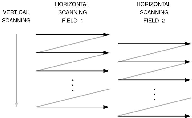
FIGURE 7. Interlaced displays first “paint” one half of the image (odd lines), then the other half (even lines).
Given this advantage of interlacing, why bother to use progressive?
With interlace, each scan line is refreshed half as often as it would be if it were a progressive display. Therefore, to avoid line flicker on sharp edges due to a too-low refresh rate, the line-to-line changes are limited, essentially by vertically lowpass-filtering the image. A progressive display has no limit on the line-to-line changes, so it is capable of providing a higher resolution image (vertically) without flicker.
Today, most broadcasts (including HDTV) are still transmitted as interlaced. Most CRT-based televisions are still interlaced, while LCD, plasma, and computer displays are progressive.
Digital Video
The most common digital video signals used are RGB and YCbCr. RGB is simply the digitized version of the analog RGB video signals. YCbCr is basically the digitized version of the analog YPbPr video signals and is the format used by DVD and the various terrestrial, cable, and satellite digital television standards (ATSC, DVB, and ISDB).
Not too long ago, DVI was introduced to consumer products for transferring digital RGB video between components. In 2004, the trend has shifted to using HDMI, which has the advantage of a smaller connector, the ability to transfer digital audio, and the ability to support both the RGB and YCbCr digital video formats.
Best Connection Method
There is always the question, “What is the best connection method for equipment?” For DVD players and digital cable/satellite/terrestrial set-top boxes, the typical order of decreasing video quality is:
- HDMI (digital YCbCr)
- HDMI/DVI (digital RGB)
- Analog YPbPr
- Analog RGB
- Analog S-video
- Analog Composite
Some may disagree about the order. However, most consumer products do digital video processing in the YCbCr color space. Therefore, using YCbCr as the interconnect for equipment reduces the number of color space conversions required. Color space conversion of digital signals is still preferable to D/A (digital-to-analog) conversion, followed by A/D (analog-to-digital) conversion, hence the positioning of DVI above analog YPbPr.
Video Resolution
Video resolution is one of those “fuzzy” things in life. It is common to see video resolutions of 720 x 480 or 1,920 x 1,080. However, those are just the number of horizontal samples and vertical scan lines and do not necessarily convey the amount of useful information.
For example, an analog video signal can be sampled at 13.5 MHz to generate 720 samples per line. Sampling the same signal at 27 MHz would generate 1,440 samples per line. However, only the number of samples per line has changed, not the resolution of the content.
Therefore, video is usually measured using “lines of resolution.” In essence, how many distinct black-and-white vertical lines can be seen across the display? This number is then normalized to a 1:1 display aspect ratio (dividing the number by 3/4 for a 4:3 display or by 9/16 for a 16:9 display). Of course, this results in a lower value for widescreen (16:9) displays, which goes against intuition.
Standard Definition
Standard definition video is usually defined as having 480 or 576 interlaced active scan lines and is commonly called 480i or 576i, respectively.
For a fixed-pixel (non-CRT) consumer display with a 4:3 aspect ratio, this translates into an active resolution of 720 x 480i or 720 x 576i. For a 16:9 aspect ratio, this translates into an active resolution of 960 x 480i or 960 x 576i.
Enhanced Definition
Enhanced definition video is usually defined as having 480 or 576 progressive active scan lines and is commonly called 480p or 576p, respectively.
For a fixed-pixel (non-CRT) consumer display with a 4:3 aspect ratio, this translates into an active resolution of 720 x 480p or 720 x 576p. For a 16:9 aspect ratio, this translates into an active resolution of 960 x 480p or 960 x 576p.
The difference between standard and enhanced definition is that standard definition is interlaced, while enhanced definition is progressive.
High Definition
High definition video is usually defined as having 720 progressive (720p) or 1,080 interlaced (1,080i) active scan lines. For a fixed-pixel (non-CRT) consumer display with a 16:9 aspect ratio, this translates into an active resolution of 1,280 x 720p or 1,920 x 1,080i, respectively.
However, HDTV displays are technically defined as being capable of displaying a minimum of 720p or 1,080i active scan lines. They also must be capable of displaying 16:9 content using a minimum of 540 progressive (540p) or 810 interlaced (810i) active scan lines. This enables the manufacturing of CRT-based HDTVs with 4:3 aspect ratios and LCD/plasma 16:9 aspect ratio displays with resolutions of 1,024 x 1,024p, 1,280 x 768p, 1,024 x 768p, and so on, lowering costs.
Audio and Video Compression
The recent advances in consumer electronics — such as digital television, DVD players and recorders, digital video recorders, and so on — were made possible due to audio and video compression based largely on MPEG-2 video with Dolby® Digital, DTS®, or MPEG audio. New audio codecs (such as MPEG-4 HE-AAC and WMA Pro) and new video codecs (such as H.264 and SMPTE VC-1) offer much better compression than legacy codecs for the same quality. These advances are enabling new ways of distributing content (both to consumers and within the home), new consumer products (such as portable video players and mobile video/cell phones), and more cable/satellite channels. NV