If you ask several electronic engineers, technicians, scientists, or professors which way current in an electrical circuit flows, some will tell you that it flows from the negative terminal of a supply through a load to the positive terminal of the supply. Others will tell you just the opposite, that current actually flows from the plus side of the voltage source to the minus.
Who is right? How can so many technical professionals be confused about something so basic as current flow? Do we even know which way current flows? And, in fact, does it actually matter which direction current flows? Let's clear all of this up.
Why Is This So Important?
The core principle of every electronic application is the control of current flow. Think about it. Isn't everything we do in electronics designed to control current flow in some way to produce a useful outcome like TV, computers, or cellular telephones? Take a look at Figure 1. This very simple model represents all electronic applications. We produce inputs that are some type of electronic signal, process them in some way, then generate appropriate output signals. For example, the input signal may come from a microphone. It is processed by an amplifier to increase its power level. The output drives a speaker.
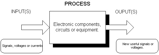
FIGURE 1. Simplified model of all electronic circuits and equipment.
Now, consider again what is in that box labeled "process" in Figure 1. In its simplest form, it may just be one electronic component such as a resistor. But it could also be a circuit like an instrument amplifier or millions of MOSFETs as in a Pentium microprocessor.
Now look at Figure 2. Here is another way to help you visualize what happens in all electrical or electronic circuits. A voltage source initiates current flow in a load. The voltage source may be a battery, signal generator, power supply, radio signal, or a signal from a transducer like a microphone or photocell. The load is the device that produces some useful end result. It could be a light bulb, heating element, motor, solenoid, or just another electronic circuit. Now, note the control element. This is the electronic component or circuit that controls the current in the load.
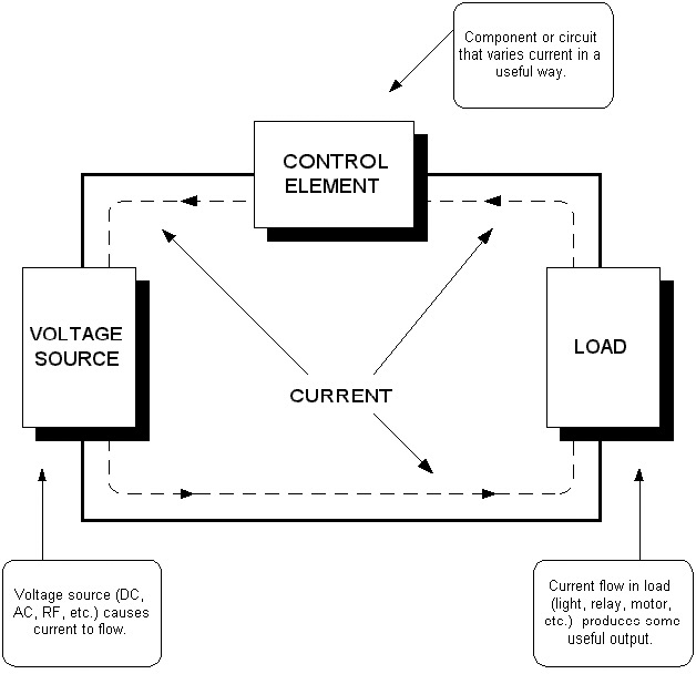
FIGURE 2. Simplified explanation of how all electronic circuits work.
The control circuits may be more complex like an op-amp or a batch of logic gates or even a complete collection of different electronic circuits. The components and circuits control the current produced by the initial input in various ways, sometimes in many different sequential and parallel steps, until an appropriate output is generated. The bottom line here is that generating and controlling current is what electronics is all about.
Conventional Current vs. Electron Flow
Scientists, engineers, college professors, and others have known for over 100 years that current is really moving electrons. Yet they have continued to use the original positive-to-negative current flow model. This has come to be known as conventional current flow (CCF). Today, this concept is still widely used and almost universally still taught in science and engineering programs.
It wasn't until the mid-20th century that electron flow (EF) was widely taught. This came about as a result of the massive training of electronic technicians during World War II. The Army and Navy decided that electron flow was more appropriate than conventional current flow, so they developed all of their classes and training materials using electron flow. After the war, electron flow caught on and became the primary way of teaching technicians in community colleges, technical institutes, and vocational schools. Why the scientific, engineering, and academic communities refused to change to electron flow is not known. It is likely that the feeling was that electrical theory was always taught using the conventional current flow model and there was no particular need, desire, or reason to change. Change is difficult and tradition dies hard.
Just What Is An Electron?
An electron is a subatomic particle, one of several different parts of an atom. Atoms are the tiny particles out of which all matter is made. Everything we know, feel, see, touch, and smell is composed of atoms. Atoms are the smallest particle of materials we call elements. Elements are the basic building blocks of nature. Typical elements are oxygen, hydrogen, carbon, copper, silver, gold, and silicon. If you take a piece of copper, for example, and divide it again and again until you get the smallest possible piece that is still recognizable as copper, then you have one copper atom. Anything that is not a basic element is made up of two or more elements combined to form what we call compounds. Water is a compound of two hydrogen atoms and one oxygen atom — you know, H2O. Salt is a compound of sodium and chlorine (HCl). The smallest recognizable particle of a compound is called a molecule.
The atoms can be further divided into smaller parts. Since no one has ever really seen an atom, physicists have for centuries theorized about what an atom looks like and is made of. One popular theory says that an atom consists of a center nucleus made up of tiny particles called protons and neutrons. The protons have a positive electrical charge. Neutrons are, of course, neutral. Orbiting around the nucleus are rings or shells of electrons. The electrons have a negative electrical charge. There are as many electrons as there are protons so the atom is balanced electrically or neutral. The number of protons in an atom is its atomic number and that number establishes the characteristics of the element.
Figure 3 shows an atom of copper. There are 29 protons and 29 electrons. Notice the outer shell of the atom. This is called the valence shell as it contains the electrons that combine and react with other elements to form chemical bonds in compounds.
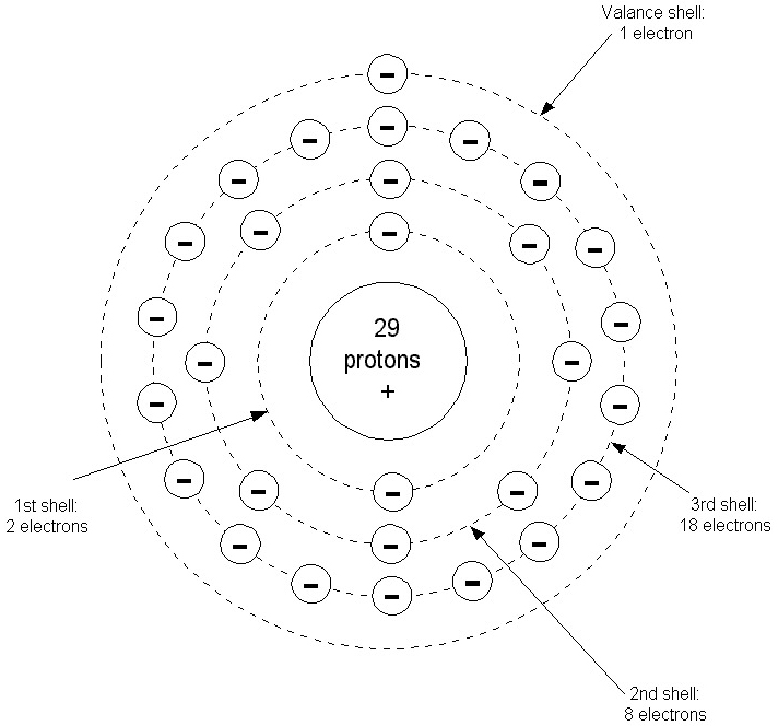
FIGURE 3. The copper atom.
And it is the electron or electrons in the outer valence shell that are freed up to produce current flow in electrical and electronic components and circuits.
How Current Flows
Current flow in most electrical and electronic circuits is electron flow. However, there are some special cases where other particles are involved. Assume that a copper wire is connected between the positive and negative terminals of a flashlight cell as in Figure 4. An excess of electrons accumulates on the negative terminal of the cell while the positive terminal has a shortage of electrons. This condition is caused by the chemical action in the cell.
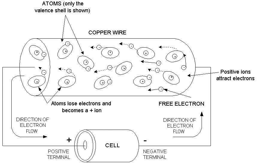
FIGURE 4. Electron flow in a copper wire.
When the copper wire is connected to the cell, two things happen. First, the positive terminal pulls the valence electrons away from copper atoms in the wire. When an atom loses one or more electrons, it becomes a positive ion because it now has more protons than electrons. Being positive, the ions attract other negative electrons from neighboring atoms thus creating a chain reaction of current flow.
At the same instant, the negative terminal of the cell repels the valence electrons from the nearby atoms in the copper wire. These freed electrons are attracted to the positive ions created by the positive terminal of the cell. The net result is a massive movement of electrons from the negative terminal of the battery to the positive terminal. This is how current flows in wires and cables and most electronic components.
Not all current flow is by electron movement. In some cases, the current is actually the movement of other current carriers. For example, holes are unique to current flow in certain types of semiconductor materials. Ion flow is the method of current flow in plasmas and electrochemical reactions in batteries.
Current Flow In Semiconductors
A semiconductor is a special type of material whose resistivity or conductivity falls somewhere between that of good conductors, like copper and aluminum, and insulators such as glass, ceramic, or plastic. Semiconductors are unique in that they can be made to have any degree of conduction desired. Of course, semiconductors are the materials from which diodes, transistors, and integrated circuits are made.
The most common semiconductor material is the element silicon (Si). Germanium (Ge) is another semiconductor element. There are also semiconductor compounds like gallium arsenide (GaAs), indium phosphide (InP), and silicon-germanium (SiGe). Silicon, like other semiconductor materials, is unique in that it has four valence electrons. This characteristic causes the silicon atoms to bond together in such a way that they share their valence electrons. The result is a unique crystal lattice structure like that shown in Figure 5. Only the valence electrons are shown. Note how the atoms share their valence electrons with adjacent atoms. The result of this is that each atom thinks that it has eight electrons in its outer orbit. This causes the material to be extremely stable.
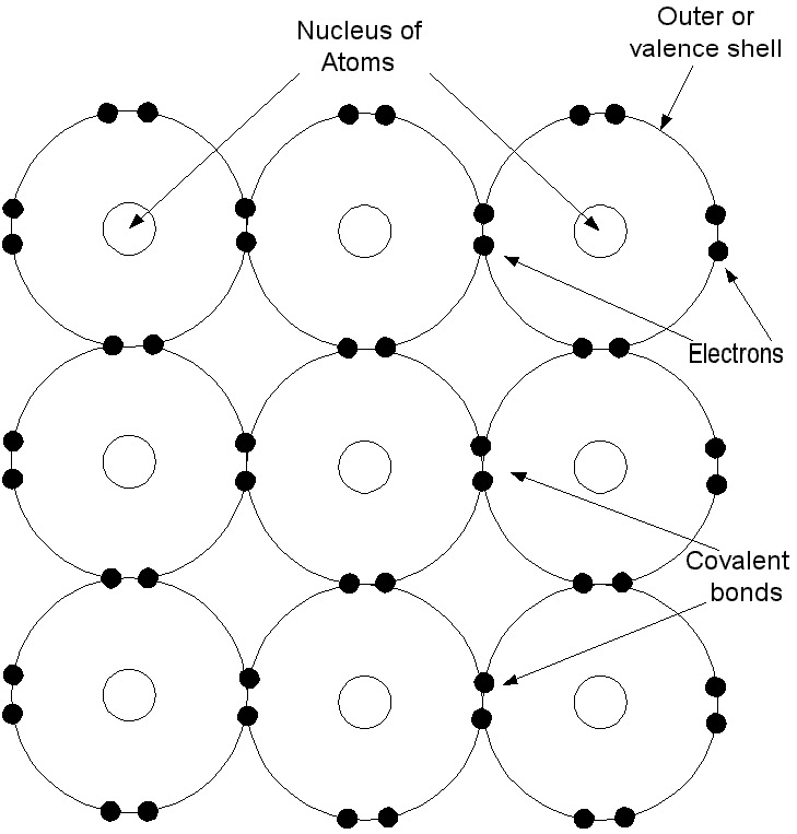
FIGURE 5. Pure silicon consists of atoms that form covalent bonds with adjacent atoms to form a crystal lattice structure.
The silicon atoms form what is called a crystal lattice structure. All of the valence electrons are fully occupied as they are shared amongst the atoms. What this means is that in a pure silicon crystal lattice structure, no electrons are available for electron flow as they are all occupied in their co-valent bonds. As a result, semiconductors like silicon in a pure state are essentially insulators. Of course, if sufficient heat is applied to the silicon or a high external voltage is applied, some of the electrons can be pulled free to cause a small amount of current flow.
To make silicon conduct, we add other chemicals to it. This process is called doping. By doping the silicon with chemicals that have either three or five valence electrons, we can create silicon in which current easily flows. Figure 6 shows what happens when we dope silicon with arsenic (As). Arsenic has five valence electrons. Four of the electrons combine with the electrons in the adjacent silicon atoms to form co-valent bonds as before. However, there is one extra electron left over. This extra electron is available for current flow.
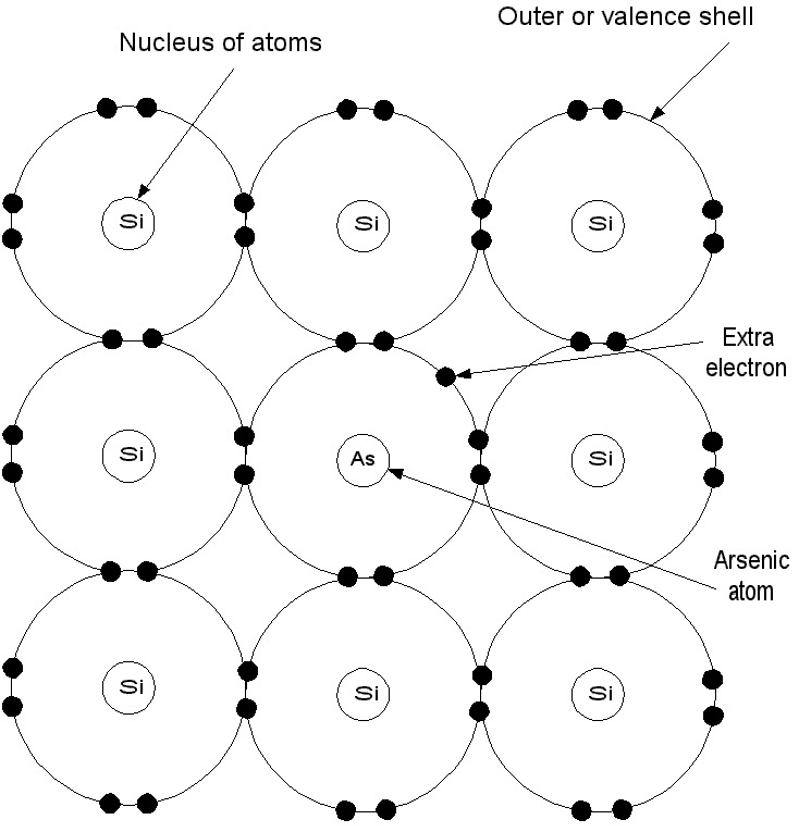
FIGURE 6. N-type semiconductor material uses electrons for current flow.
Silicon doped with chemicals that have an extra electron is referred to as an N-type semiconductor. The "N" means negative, which refers to the extra negative electron. When an external voltage is applied to a piece of N-type semiconductor material, current easily flows as the unbound electrons are attracted and pulled through the silicon by the external voltage. If the silicon is heavily doped with arsenic, many free electrons are available and a high amount of current will flow. This is the same as saying that the material has a very low resistance. If only a few arsenic atoms are added, fewer electrons are available for current flow so the current level will be less with an external voltage. Such material has a much higher resistance.
As you can see, current flow in N-type semiconductor material is still by electrons. However, we can also dope the silicon with a material that has only three valence electrons. This is illustrated in Figure 7 where the silicon is doped with boron (B) atoms.

FIGURE 7. P-type semiconductor material where holes are the current carriers.
The three valence electrons in the boron atom form co-valent bonds with adjacent silicon atoms. However, one of the silicon atoms is missing an electron. This missing valence electron is referred to as a hole. A hole, therefore, is not an actual particle, but simply a vacancy in the valence shell of the crystal lattice structure that acts like a current carrier. This vacancy or hole has a positive charge. If an electron passes near the hole, it will be attracted and it will fill the hole, completing the co-valent bond.
Current flow in this type of semiconductor material is by way of holes. This type of semiconductor material is referred to as P-type material. P means positive, which refers to the charge of the hole.
When an electrical voltage is applied to a piece of P-type semiconductor material, electrons flow into the material from the negative terminal of the voltage source and fill the holes. The positive charge of the external voltage source pulls electrons from the external orbits, creating new holes. Thus, electrons move from hole-to-hole. Electrons still flow from negative-to-positive, but holes move from positive-to-negative as they are created by the external charge.
Ion Flow
In certain types of materials, particularly liquids and plasmas, current flow is a combination of both electrons and ions.
Figure 8 shows the simplified drawing of a voltage cell. All cells consist of two electrodes of different materials immersed in a chemical called an electrolyte. The chemical reaction that takes place separates the charges that are created. Electrons pile up on one electrode as it gives up positive ions creating the negative terminal while electrons are pulled from the other electrode creating the positive terminal.
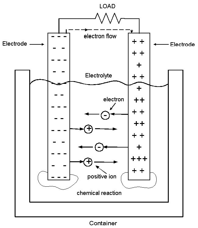
FIGURE 8. Current flow in a chemical cell.
Whenever you connect an external load to this battery, electrons flow from the negative plate, through the load, to the positive electrode. Inside the cell, electrons actually flow from positive-to-negative while positive ions move from negative-to-positive.
Living In Denial
So why do we continue to perpetuate the myth of conventional current flow (CCF) when we have known for a century that current in most electrical and electronic circuits is electron flow (EF)? I have been asking that question of my colleagues and others in industry and academic for years. Despite the fact that electron flow is the reality, all engineering schools insist on teaching CCF. If you were in the armed services or came up through the ranks as a technician, chances are you learned and favor electron flow.
The way you learned it in school is what you tend to use when you design, analyze, troubleshoot, or teach out in the real world.
Does It Really Matter?
As you may know, it doesn't really matter which current direction you use as circuit analysis and design works either way. In fact, this issue only affects DC that flows in only one direction. In alternating current, electrons flow in both directions, moving back and forth at the frequency of operation. But if it truly does not matter which direction we assume, then why don't we default to the truth and end this nonsense once and for all?
In Conclusion
If you ever want to start a lively conversation, maybe even an argument, try bringing up this subject in a group of technical people. You just may be surprised at the intensity of the feelings and the sanctimonious attitudes on both sides. I've done this numerous times and I am still amazed at the emotional response this issue generates.
My conclusion is that the concept of CCF will never be abandoned. It is somewhat akin to forcing us all to switch to the metric system of measurement using meters and Celsius rather than feet and Fahrenheit with which we are more familiar and comfortable. CCF will continue to be taught from now on. I have come to accept this whole thing as one of the stranger quirks of electronics. NV
HISTORICAL NOTE
Early researchers of electricity first discovered the concept of voltage and polarity, then later went on to define current as the motion of charges. The term voltage means the energy that makes current flow. Initially, voltages were created by static means such as friction or by lightening. Later, chemical cells and batteries were used to create a constant charge or voltage. Mechanical generators were developed next.
Charges refer to some kind of physical object that moves when it is subjected to the force of the voltage. Of course, back in the 18th century, those working on electrical projects didn't really know what the charges were. For all they knew, the charges could have been micro miniature purple cubes inside a wire or other conductor. What they did know was that the voltage caused the charges to move. For purpose of analysis and discussion, they arbitrarily assumed that the charges were positive and flowed from positive-to-negative. This is a key point. They didn't really know the direction of current flow, so they theorized what was happening. And, as it turned out, they guessed wrong. There is nothing wrong with being wrong as scientists are often hypothesizing one thing, then later finding that the truth is something else. The big mistake is that the incorrect hypothesis has been retained and taught as truth.
In the late 19th century, it was finally determined that the charges being discussed were really electrons and the current was really electrons flowing from the negative terminal of a voltage source through the circuit to the positive side of the voltage source. British physicist, Joseph J. Thomson made this discovery in1897. The truth was at last proven and revealed.
The case for conventional current flow.
- It is traditional.
- Most engineers and some techs have learned it this way.
- It is a lot of trouble to change things like engineering textbooks and schematic symbols (the arrows in diodes and transistors point in the direction of CCF).
- Human nature abhors change.
- CCF has become a de facto standard.
The case for electron flow.
- It is the truth.
- The operation of electronic devices is easier to explain and learn using electron flow.
- Why not standardize on the way it really is?