A previous article about vacuum tubes and tube-based equipment included a sidebar about safety with tube-level voltages — it seemed to me an article on some of the issues associated with those voltages would be interesting. There are lots of circuits for generating high voltages out there, but what about the “gotchas?”
How High is High?
Let’s talk a bit about what the “high” in “high voltage” means. To a designer of logic ICs, a few tens of volts might be “high voltage.” In the AC power world, voltage might need to exceed 1 kV to be properly classified as “high voltage.” To the Tesla coil builder or EMC (electromagnetic compatibility) engineer, several kilovolts (kV) might be needed to get the high voltage juices flowing. This column will assume you’re working with AC line voltages and higher.
Safety Basics
Start by referring to the sidebar “High Voltage Safety” in the previous article. All of those things are important. A comment in the digital Nuts & Volts issue by Larry Reynolds K4MLA noted an old and effective rule: “When working with high voltage equipment, keep one hand in your pocket.”
Why this is a safe practice is discussed below in the sidebar. Heed that rule and all those in the Vacuum Tubes article — we want you as a reader for a long time!
Hand in the Pocket
One of the oldest rules in the ham’s safety list is to keep one hand in your pocket or behind your back whenever adjusting or measuring equipment containing a voltage high enough to be a safety hazard. Why? Most workbench shocks come from a hand or arm touching an energized component or wire.
If the lowest resistance path for that current goes through your other hand, that conducts current through your heart and that is the most dangerous path. So, don’t create that path!
If you’re wearing pants and shoes with insulating soles, the current path has a much higher resistance so less current will flow. Better yet, the path from a hand to a foot doesn’t go through the heart. Make it a habit to work one-handed around energized equipment and you’ll be a step ahead of electricity.
Fuse Ratings
We’re all familiar with the maximum current rating for a fuse, but fuses have a voltage rating too. If you have a glass cartridge fuse handy, on the end with the current ratings stamped into or printed on the metal there will also be a voltage; for example, “3A 250V.” The rating tells you how much voltage the fuse can withstand after the element melts and opens.
Be aware that a fuse needs to withstand the peak AC voltage which is 1.414 times the RMS voltage. Peak voltage in a 120V AC circuit can easily exceed 170V. In higher voltage circuits, special HV fuses must be used.
If the voltage across the fuse is higher than its rating, an arc may develop. The arc may continue to conduct current, defeating the purpose of the fuse entirely! Some fuses for higher voltages are filled with sand or another insulating material that block current after the metal element melts. Never use a low voltage fuse in a higher-voltage circuit.
When can you use an automotive-type blade fuse? They are inexpensive and widely available, but the standard ATO fuse is only rated for 32V. These must not be used in a circuit connected to, say, the AC line’s 120V RMS.
Another tip — when wiring a panel-mount holder for cartridge-style fuses: Connect the “hot” or “live” circuit to the rear contact so that when the fuse is removed from the holder, its rear contact disconnects from the power source. Otherwise, the holder will be energized as you pull the fuse out.
Grounding Stick
Veterans of broadcast and high voltage applications may refer to something called a “chicken stick” or “grounding stick.” Figure 1A shows a typical commercial model. To use the stick, turn off the equipment and wait for 30 seconds to one minute (or for as long as metering shows significant voltage is present). This allows charged capacitors to be drained by bleeder resistors (high-value resistors connected directly across the capacitors). If practical, disconnect the power source for the equipment and insure it can’t be turned on again while you’re working on it.
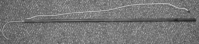
FIGURE 1A. The top photo (A) is a commercial grounding stick. The handle is a phenolic resin rod approximately two feet long. The bottom drawing (B) shows how to build your own grounding stick. Be sure the ground wire is outside the handle, and use a heavy ground clip. Never touch the ground wire while using the stick. (Figure courtesy of ARRL.)
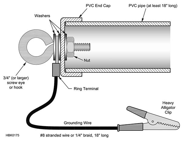
FIGURE 1B.
Save the Screwdriver
Never (repeat after me ... never) use a screwdriver as a grounding stick. They aren’t designed or intended for that use.
The handle may look like it has a lot of plastic, but you don’t know if it’s a good insulator or not. There may be small internal cracks that result in a lot less insulation than you think!
Screwdriver handles are often dirty or greasy which creates a somewhat conductive path from the blade to your hand. Plus, if you do happen to discharge a big capacitor, you’ll probably ruin the blade with a big pit.
Take a few minutes and make yourself a good grounding stick. Your screwdrivers will thank you for it!
Once the meters show the power supply capacitors have discharged, open the equipment and attach the stick’s ground lead to the power supply common. (Common is usually but not always the metal enclosure — don’t assume that it is; verify first.) Put on some safety glasses — just in case. Holding the stick by the insulated portion (never hold the ground lead in your fingers), touch its tip to every point in the circuit where voltage can be present. Only then is the equipment safe to work on.
If you don’t have a grounding stick, you can make one as shown in Figure 1B. Note that the ground lead is attached outside the PVC tubing. (Dry wood, fiberglass, or plastic rod will also work.) The ground wire should be extra heavy (#8 AWG or larger) because it might have to withstand high current when a fully-charged capacitor is discharged. Shorting out that charged capacitor you thought was discharged will certainly get your attention!
Meter Ratings
Another surprise to hobbyists is that voltmeters themselves can be a source of danger. A maximum voltage rating is printed on your meter (see Figure 2). Heed it! That is the maximum voltage the probes, connectors, and body of the meter can withstand. A higher voltage may cause a flashover from the wiring to anything touching the case, such as your hand.

FIGURE 2. Voltage ratings are shown next to a voltmeter’s probe jacks (1,000V DC and 750V AC). Exceeding these voltages can result in a flashover, also presenting a severe electrocution hazard.
Electrocution caused by using meters beyond their voltage rating happens regularly. In the photo, note that the probes are recessed for extra insulation — use the right probes for the full rating.
If you use a voltmeter to measure high voltages, power-down the equipment, discharge the high voltage points, then attach the meter to the point being measured. Place the meter where you can see it. Then, power-up the equipment and take a reading. That way, you’re not touching the meter when it’s energized.
Special high voltage probes (such as the Fluke 80K-40 or B&K HV44-A) are available for the multi-kV voltages sometimes found in tube gear. Remember, it’s not a race. Take your time.
Switch to Safety
Finally, follow the “switch to safety” rule long promoted by the ARRL (American Radio Relay League) in its literature. One of the ARRL’s early technical pioneers, Ross Hull, died in 1938 from an electric shock when working on transmitting equipment. The “Switch to Safety” campaign began thereafter.
Don’t work on live equipment unless it’s absolutely necessary, and then take precautions. Follow basic safety procedures at all times.
Don’t work alone and know how to respond if someone else does get a shock or burn. CPR courses are often available through a public safety agency like police or fire at very low cost or free. Electrical safety classes may be available through your power utility or an electrician’s trade union.
Know how to remove power and show your friends and family how to remove power in your shop or station. This all sounds like a lot of bother I’m sure, but you won’t regret having those skills if they are ever needed.
Avoid Crack Attacks
If you’re like most electronic-ers, you never throw anything away — especially test instruments and accessories. In the world of high voltage, this can be dangerous.
As probes, fixtures, and connectors age, their insulation can become brittle and crack. That crack compromises the insulation, and you can even come in direct contact with the internal wiring.
Before beginning a high voltage project, carefully inspect your test probes and other equipment. Make sure the insulation is clean, flexible, and not scuffed or cracked so it can protect you as you expect.
Static Voltages and ESD
ESD stands for electrostatic discharge. Anyone who has gotten a shock from walking across a carpet and touching a grounded object has experienced ESD. Figure 3A shows the IEC-61000-4-2 ESD waveform used for testing devices that will be subjected to static electricity. Pulse voltages are typically around 2 kV but can be as high as 15 kV! The various models and tests are discussed in the STMicroelectronics document DM00023467.pdf which is available online.
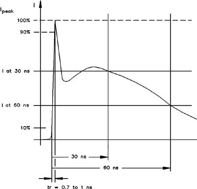
FIGURE 3A. The IEC 60001-4-2 electrostatic discharge (ESD) waveform (A- top). The Human Body Model (HBM) circuit (B- bottom) is used to perform ESD testing on equipment.
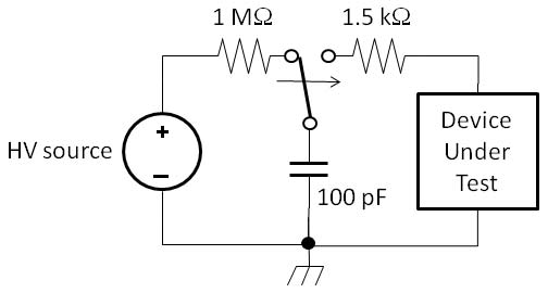
FIGURE 3B.
Figure 3B shows a typical ESD test pulse generator based on the Human Body Model or HBM. The HV source is set to the desired voltage and the 100 pF capacitor representing the body is charged. A test probe is connected to the Device Under Test (DUT) and the switch is thrown, discharging the capacitor through it. (This is the contact discharge test. If the capacitor is discharged through an air gap, that is the air discharge test.)
Static electricity can certainly pack a punch — ask any cat in the winter! The pulse can destroy sensitive electronics and also upset their operation. Use of static-discharge equipment in your workshop and when working on equipment is a great idea and not expensive.
Nevertheless, ESD doesn’t present a direct hazard to humans. There simply isn’t enough energy to cause burns or significant shocks.
High Voltage Components
When building high voltage circuits, be sure to select components intended for that use. High voltage doesn’t just result in higher power dissipation; there are special stresses to account for.
Resistors
Resistors have maximum voltage ratings aside from their power dissipation rating. For example, a 1/4 watt carbon-film resistor with axial (wire) leads has two primary voltage ratings: maximum working voltage (MWV); and maximum overload voltage (MOV). (See the datasheet for Yageo CFR resistors at www.mouser.com.)
The first represents the “normal” maximum voltage the resistor should experience on a regular or continuous basis. The second is a temporary overload voltage for pulses or transients. For these voltages, the resistor won’t arc over or break down just from voltage effects. (It might be dissipating too much power, but that’s a different issue.)
For the 1/4 watt Yageo CFR series resistors, MWV is 250V and both MOV and VP are 500V. If your circuit will have higher voltages — even if the resistor’s power dissipation is not exceeded — an arc across the body may occur.
Surface-mount resistors have very low voltage ratings because they are so small. The typical voltage rating for body size 0603 components is 75V, an 0805 can handle 150V, and 1206 components up to 200V. This applies to all the components in SMT packages.
For voltages above a few hundred volts, you’ll need to use resistors that are physically larger with a longer body and more insulation from lead to lead. Compare the Yageo HHV series of high voltage resistors to their lower voltage cousins. They are longer and have broad end caps that act similarly to the insulating discs on power-line insulators. These resistors have MWV ratings starting at 1,600V.
Capacitors
You’re probably more familiar with capacitor voltage ratings. These are generally working voltage ratings for continuous use. Depending on the type, the capacitor may also have pulse overload ratings or peak voltage ratings that represent the absolute maximum voltage the dielectric can withstand. Once the dielectric breaks down, the capacitor is generally destroyed. In a high voltage power supply, this type of failure is not subtle!
For typical tube circuits, ceramic and mica, plastic film, and oil-filled capacitors are normally used, in order of increasing capacitance. Disc ceramic and mica capacitors are very common with values of 0.1 μF or less and ratings up to 1 kV. Film capacitors are generally available with ratings up to 600V and values up to 1 μF or so.
Oil-filled capacitors are commonly available with capacitances in the 1 to 50 μF range and voltage ratings up to several kV. Old units are available as surplus and are often removed from old equipment. Be wary of old oil-filled capacitors! Really old ones made in the 1960s and 1970s often have PCBs (a carcinogen) in the insulating oil.
You can often take these old capacitors to a local utility or recycling center for proper disposal. Some locations have hazardous waste disposal events where they will take these old components. It should be obvious that you don’t want to use them if the oil is leaking from the seals or if the enclosing can is dented or punctured. Once discharged, it’s good practice to install a shorting wire across the capacitor to avoid self-charging to hazardous voltages.
Vacuum- and air-variable capacitors are often used for tuning or adjusting high power RF circuits. Vacuum capacitors have voltage ratings of 10 kV or more and values up to 2,000-3,000 pF. The electrodes are copper cylinders, and the variable models move one cylinder with a threaded shaft attached to flexible copper bellows.
Air-variables have somewhat lower voltage ratings. Semi-circular plates connected in parallel are interleaved to create the necessary area. One set of plates is attached to a rotating shaft to vary the amount by which the plates overlap to change the capacitor’s value.
These capacitor types are non-polarized, meaning they can be used with AC or either DC voltage polarity. However, you should pay attention to which electrode is closest to the outside of the capacitor’s insulation. This is often marked with a line on the component’s body.
The reason this matters is that many capacitors are connected with one electrode tied to circuit common or chassis ground. If the capacitor fails shorted, connecting the outer electrode to the lower voltage point reduces the safety hazard.
If you’re going to connect capacitors directly to the AC line, you should use X- and Y-type self-healing metalized film capacitors. X capacitors are connected from line to line, and Y capacitors are connected from line to ground. These capacitors are safety-tested to minimize fire or shock hazards.
Energy-Storage or Filter Capacitor?
Browsing through websites or rooting through boxes of capacitors at a flea market, you will encounter capacitors that have pretty high values and voltage ratings — but they’re so small! What’s the deal?
These are probably energy-storage or photoflash capacitors for pulse discharge use, like in a camera flash unit. They are intended to be charged up, hold that energy, and then discharge it all at once.
Filter capacitors, on the other hand, are intended to have a continuous AC ripple current through them as they store and release energy in a power supply or other filter circuit. This continuous current creates heat in the capacitor which must be dissipated.
An energy-storage capacitor is not manufactured to withstand that stress and while it may work “for a while,” it’s best to use the physically larger filter capacitor. Similarly, the filter capacitors may have too much inductance to discharge as quickly as an energy-storage capacitor.
Even though the two types may have the same value and voltage rating, they behave very differently. Know that difference!
Dust and Dirt
Dust, dirt, and grime are the mortal enemy of high voltage electronics. Not only do they make it harder for a component to dissipate heat, they can be conductive too. High voltages also attract other particles such as oil mist or water vapor. The result can be a surprisingly large buildup inside your equipment.
Once foreign substances get inside, they are electrostatically attracted to surfaces, wires, and components by the high voltages. Eventually, enough accumulates to create a physical connection between two points at different voltages — such as from one end of a resistor to the other, across an insulator, or from a high voltage point to ground. This creates a leakage path and small leakage currents start to flow.
As long as it stays small, this current may not be a problem. If the material is organic (fibers, hair, oil, or grease), it will eventually start to break down and carbonize. This lowers the resistance and increases the current in a cycle that eventually causes the material to break down and create a carbon track like a resistor. There may be an arc or the current may just upset the circuit functions. Either way, you’ll need to find and clean away the track before it becomes permanent, damages components, or starts a fire.
The best way to prevent this from happening is twofold. First, prevent the contamination from getting into the equipment in the first place. Use filters on fan and ventilation openings and don’t let dust accumulate around the equipment. Second, open up and clean high voltage equipment on a regular basis.
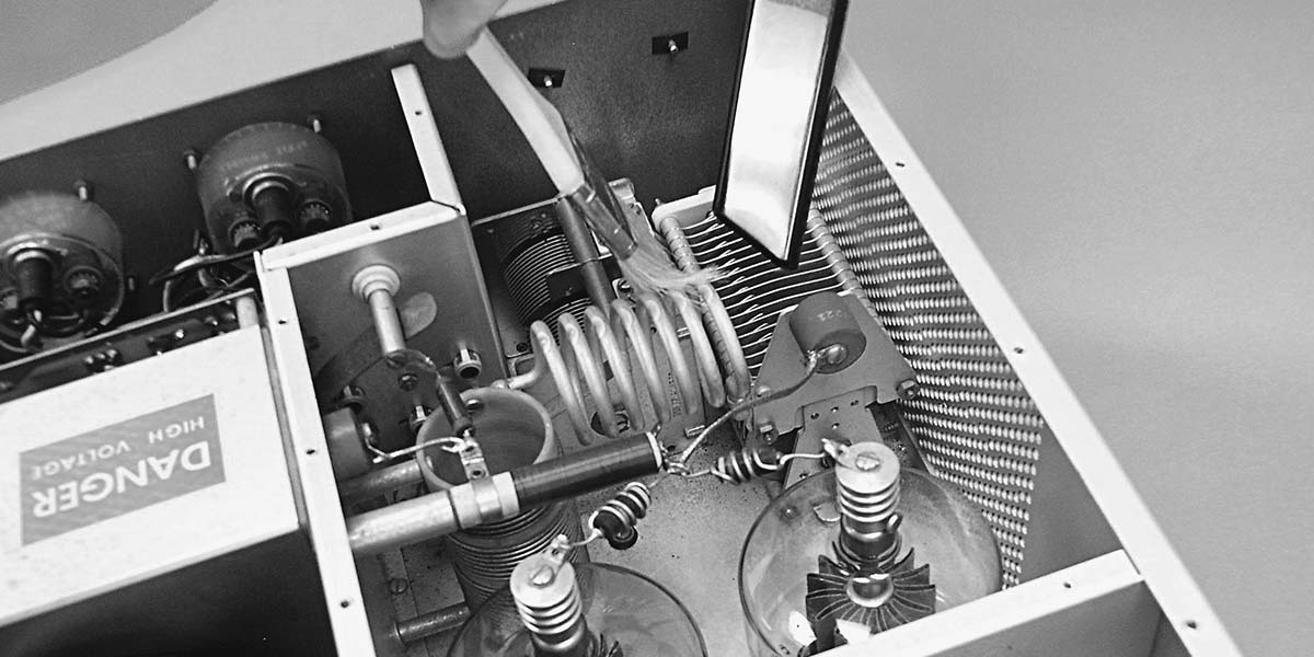
Figure 4 shows a good method of using a paint brush and vacuum cleaner to do the job.
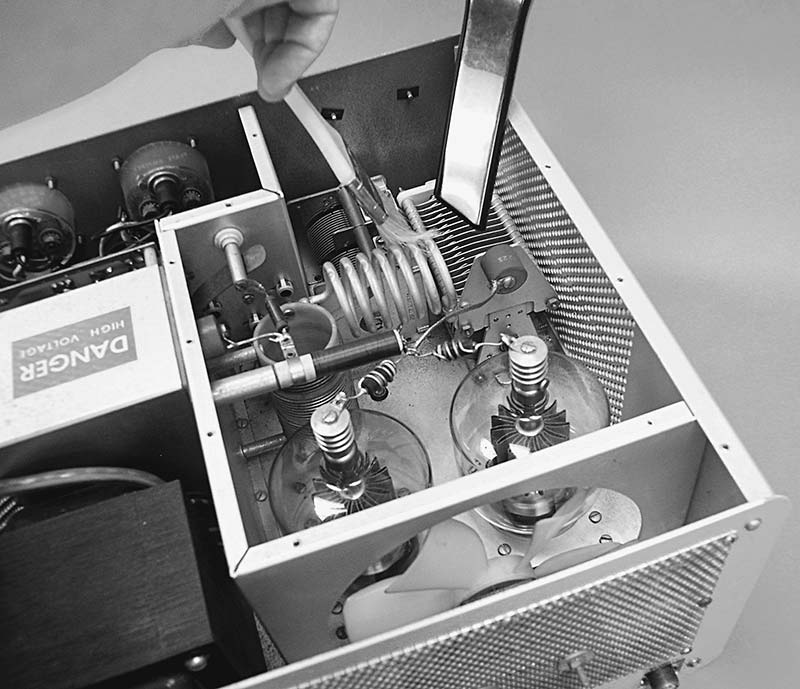
FIGURE 4. Cleaning high voltage equipment can be done with a small paintbrush and home vacuum crevice cleaning attachment. Knock the dust loose with the paintbrush into the vacuum cleaner. Avoid blowing dust away as it will only get into hard-to-reach places or into other equipment. (Photo courtesy of ARRL.)
Knock the dust loose with the brush and vacuum it up. Don’t blow the dust away as it just gets deeper into crevices and flies away to other places it shouldn’t be. For stubborn or caked-on material or grease/oil deposits, use a soft cloth and mild solvent to remove it. (If you use soap and water, be sure to clean away any soap residue with a water-only wipe.) After cleaning with liquids, let the equipment dry thoroughly before turning it back on.
After you’ve cleaned the equipment, give it a close visual inspection for any problems that might be starting. This is a good time to look for carbonized or scorched material, cracked insulators or insulation, and loose wires.
Be Smart
In closing, remember the number one rule for working with or around high voltage: Be smart! You might not get a second chance. This is particularly important if you are used to working on low voltage circuits and equipment.
There are lots of “beginner” kits and projects for Tesla coils and various arc-and-spark devices. The voltages involved can be lethal. If you aren’t used to high voltage techniques, on that first adventure up the voltage scale work with someone who is. Be extra cautious. Measure twice. Don’t assume anything is off or discharged without verifying it. Make good use of that grounding stick. And, of course, switch to safety! NV
A Tube-Based Bench Supply for Tube Projects
If you like building tube gear, you’ll probably have to build your own power supply. Not too many manufacturers are selling adjustable regulated HV supplies these days! Bryant Julstrom KCØZNG (an ARRL Handbook contributor and prolific builder) designed just such a power source in his August 2014 QST article that is downloadble at www.arrl.org/files/file/QST/This%20Month%20in%20QST/August%202014/JULSTROM.pdf.
The supply output of 150-260 VDC is regulated up to 50 mA. A 6.3 VAC output for filaments is also available. Just the thing for getting your “hollow-state” designs up and running!