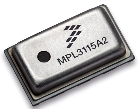
Let’s take a look at what is required to read sensor data from an I2C interface (a.k.a., I2C, IIC, TwoWire, TWI). In particular, we’ll be reading data from the NXP MPL3115A2 altimeter/barometer/temperature sensor. The principles found here can also be applied generically, even to your ambifacient lunar wane shaft positioning sensor of your turboencabulator.
Why I2C
I2C is a very popular go-to for sensors because of its simplicity and expandability over other interfaces such as UART and SPI. SparkFun (a Colorado based company which markets to the maker crowd) has a nicely written and friendly tutorial on I2C you should take a look at if you’re interested in more. For this article, it’s sufficient to say I2C has been winning the hearts of sensor manufacturers, and has thus become very popular for complex smart sensors.
Prototyping with the MPL3115A2 Breakout Board
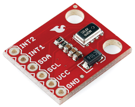
NXP’s MPL3115A2 sensor — with its tiny footprint — isn’t what you would call prototyping or breadboard friendly. Therefore, we’re going to be using a convenient ready-made breakout board from SparkFun (part no. SEN-11084; www.sparkfun.com). The only assembly required is to add some breakaway headers for ultimate breadboard friendliness. If we were to go into production, we’d order the sensor direct from NXP and make our own printed circuit board (PCB) daughter boards for use with our single board computer (SBC) or module.
Pro Tip: There are many outfits like SparkFun providing breakout boards to choose from, such as Pololu, Adafruit, Seeed Studio, and Trossen Robotics just to name a few.
Hookup to a Single Board Computer
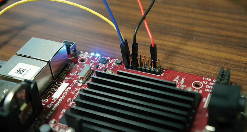
Now that we have the sensor, it’s obvious we need to connect it to something with an I2C interface to read the data. Most any SBC or even microcontroller could do the job, but we’re going to reach for our handy Technologic Systems’ TS-7970 high performance industrial SBC with Wi-Fi and Bluetooth, since we have an IoT-like end goal in mind.
The MPL3115A2 breakout board requires no more than 3.3 VDC and a connection to SDA (I2C Data) and SCL (I2C Clock). There are two interrupt pins that can be used for things like events and triggers, but we’re not going to use those in this article. All of this is brought out on the header designated as HD3 on our TS-7970 (see section HD3 of the TS-7970 manual available at https://wiki.embeddedarm.com/wiki/TS-7970).
When we’re all hooked up and powered on, the I2C interface is brought out to the Linux device file /dev/i2c-1 (see section TWI of the TS-7970 manual). This number might change depending on your system, so be sure to run i2cdetect -l to get a list of I2C interfaces on your board.
Note: We’re making a couple assumptions at this point. One is that you already know how to boot and connect to your board. If you’re following along with a TS-7970, you may want to take a look at the Getting Started Guide (available at the same link as the manual). Another assumption we’re making is that you’re running Linux and have i2c-tools installed.
Programming the I2C Client
Official documentation for programming an I2C client in C can be found in the Linux Kernel in /i2c/dev-interface. (You can find documentation mentioned in this article at www.embeddedarm.com.)
We don’t have to be stuck using C though. You can reach for C++, Python, Java, or others. For this article, we’re going to work with C for learning purposes, and because we know C is uber fast where hardware is involved.
Pro Tip: When researching how to interface with the MPL3115A2, I stumbled upon a fantastically convenient repository in the ControlEverything community (https://github.com/ControlEverythingCommunity) that has working example code for Python, C, Java, and more. Take a look for yourself at the ControlEverything Community/MPL3115A2 github repository.
Pro Tip: If you are interested in using Python, you’ll need to install python-smbus first (https://pypi.python.org).
Once we have a basic understanding of how to program for I2C from looking at examples and documentation, we need to dive into the specifics of our sensor using the MPL3115A2 datasheet.
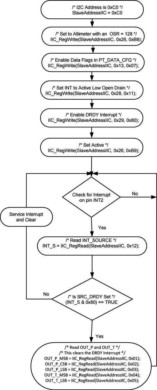
Luckily, NXP also provided a really nice application note — Data Manipulation and Basic Settings of the MPL3115A2 Command Line Interface Driver Code — which helps further our understanding of how to interface with this sensor. In section 11 (Quick Start Setup), you’ll find a flowchart showing necessary steps to read altimeter data.
Pro Tip: Since we don’t plan on using the events to trigger an interrupt pin, you should be able to skip the step of enabling data flags in PT_DATA_CFG.
Sanity Check Using i2c-tools
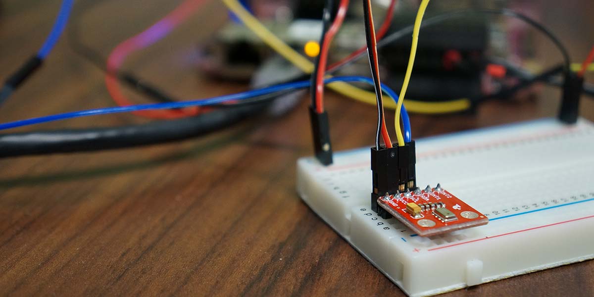
Before we dive into C code, let’s test our connections and do some basic sanity checking using the tools included in i2c-tools, like i2cset, i2cget, and i2cdetect.
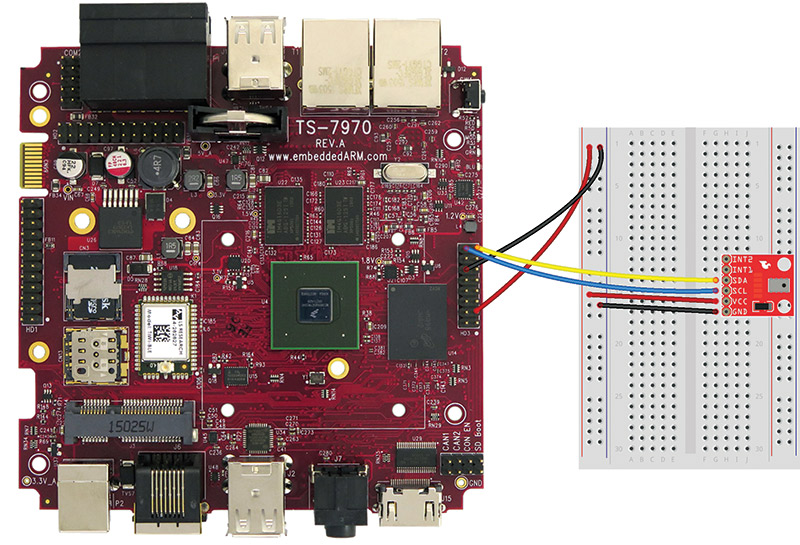
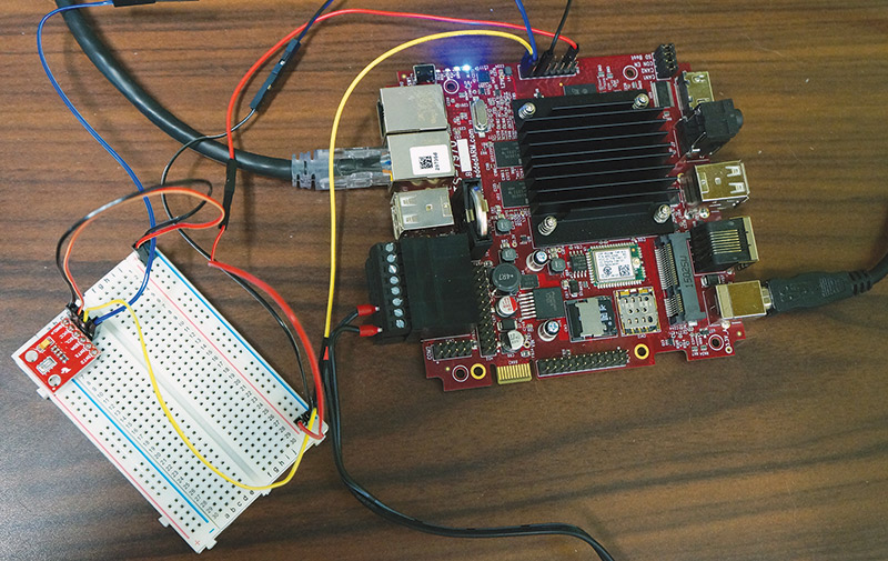
This is what our prototype connections will look like.
First, let’s use i2cdetect to both verify which device file and I2C slave address. By running i2cdetect -l, we see a list of I2C busses like so:
root@ts-imx6:~# i2cdetect -l
i2c-0 i2c 21a0000.i2c I2C adapter
i2c-1 i2c 21a4000.i2c I2C adapter
root@ts-imx6:~#
On our TS-7970, we know that /dev/i2c-0 is used internally to connect the FPGA (field-programmable gate array) with the RTC (real time clock) as mentioned in the manual, so that leaves us with /dev/i2c-1. We can then use that information to detect chips connected to /dev/i2c-1 by running i2cdetect -y 1, like so:
root@ts-imx6:~# i2cdetect -y 1
0 1 2 3 4 5 6 7 8 9 a b c d e f
00: -- -- -- -- -- -- -- -- -- -- -- -- --
10: -- -- -- -- -- -- -- -- -- -- -- -- -- -- -- --
20: -- -- -- -- -- -- -- -- -- -- -- -- -- -- -- --
30: -- -- -- -- -- -- -- -- -- -- -- -- -- -- -- --
40: -- -- -- -- -- -- -- -- -- -- -- -- -- -- -- --
50: UU -- -- -- -- -- -- -- -- -- -- -- -- -- -- --
60: 60 -- -- -- -- -- -- -- -- -- -- -- -- -- -- --
70: -- -- -- -- -- -- -- --
This tells us there is an I2C slave device detected at the 0x60 address. We’re on our way! Let’s try reading the register WHO_AM_I, which is defined as 0x0C. According to the datasheet, the value 0xC4 should be returned. Let’s see using i2cget -y 1 0x60 0x0C:
root@ts-imx6:~# i2cget -y 1 0x60 0x0C
0xc4
Perfect! For now, let’s conclude our little sanity check. If you’re looking for some homework, you could manually step through the flowchart using i2c-tools to see what the raw data looks like.
We’re going to move onto the C program.
The C Program
We’re going to make things easy on ourselves and use the ControlEverythingCommunity/MPL3115A2 example code as our base. This uses the same principles as taught in the official Linux I2C documentation and is well commented.
Let’s take a look:
#include <stdio.h>
#include <stdlib.h>
#include <linux/i2c-dev.h>
#include <sys/ioctl.h>
#include <fcntl.h>
void main()
{
// Create I2C bus
int file;
char *bus = "/dev/i2c-1";
if((file = open(bus, O_RDWR)) < 0)
{
printf("Failed to open the bus. \n");
exit(1);
}
// Get I2C device, TSL2561 I2C address is 0x60(96)
ioctl(file, I2C_SLAVE, 0x60);
// Select control register(0x26)
// Active mode, OSR = 128, altimeter mode(0xB9)
char config[2] = {0};
config[0] = 0x26;
config[1] = 0xB9;
write(file, config, 2);
// Select data configuration register(0x13)
// Data ready event enabled for altitude, pressure, temperature(0x07)
config[0] = 0x13;
config[1] = 0x07;
write(file, config, 2);
// Select control register(0x26)
// Active mode, OSR = 128, altimeter mode(0xB9)
config[0] = 0x26;
config[1] = 0xB9;
write(file, config, 2);
sleep(1);
// Read 6 bytes of data from address 0x00(00)
// status, tHeight msb1, tHeight msb, tHeight lsb, temp msb, temp lsb
char reg[1] = {0x00};
write(file, reg, 1);
char data[6] = {0};
if(read(file, data, 6) != 6)
{
printf("Error : Input/Output error \n");
exit(1);
}
// Convert the data
int tHeight = ((data[1] * 65536) + (data[2] * 256 + (data[3] & 0xF0)) / 16);
int temp = ((data[4] * 256) + (data[5] & 0xF0)) / 16;
float altitude = tHeight / 16.0;
float cTemp = (temp / 16.0);
float fTemp = cTemp * 1.8 + 32;
// Select control register(0x26)
// Active mode, OSR = 128, barometer mode(0x39)
config[0] = 0x26;
config[1] = 0x39;
write(file, config, 2);
sleep(1);
// Read 4 bytes of data from register(0x00)
// status, pres msb1, pres msb, pres lsb
reg[0] = 0x00;
write(file, reg, 1);
read(file, data, 4);
// Convert the data to 20-bits
int pres = ((data[1] * 65536) + (data[2] * 256 + (data[3] & 0xF0))) / 16;
float pressure = (pres / 4.0) / 1000.0;
// Output data to screen
printf("Pressure : %.2f kPa \n", pressure);
printf("Altitude : %.2f m \n", altitude);
printf("Temperature in Celsius : %.2f C \n", cTemp);
printf("Temperature in Fahrenheit : %.2f F \n", fTemp);
}
Once you have this copy/pasted or downloaded to your board, you’re ready to compile and run it. Compiling is simply done using the command gcc mpl3115a2.c -o mpl3115a2. Running ./mpl3115a2 will produce the altitude, pressure, and temperature:
root@ts-imx6:~/projects/altimeter-sensor$ gcc mpl3115a2.c -o mpl3115a2
root@ts-imx6:~/projects/altimeter-sensor$ ./mpl3115a2
Pressure : 85.36 kPa
Altitude : 20623.69 m
Temperature in Celsius : 23.56 C
Temperature in Fahrenheit : 74.41 F
Sweet success! You could do like I did and immediately go check the pressure accuracy against your favorite weather website and the altitude against a GPS or terrain map. However, the point of celebration here is that we were able to successfully interact with an I2C sensor. Now, you should have the skills and know-how to apply to your specific I2C sensor project.
Take It a Step Further
We alluded to the subject of Internet of Things (IoT) earlier, so let’s expand on that. As mentioned, our TS-7970 has Wi-Fi capabilities, and it also has the ability to run a full-fledged web server. Meaning, we could take this a step further and periodically record our sensor data to a database and then display the data on a web page, both in real time and historical charts.
You could also install node.js and develop a nice REST API, making it easy for others around the world to pull data from. The obvious use for this particular sensor is making a mini-weather station, but I’m sure you can come up with a more clever use.
Conclusion
In reading this article, you should’ve come away with a bunch of information on how to interface with an I2C sensor device. We started by looking at why I2C is a popular choice and pointed you towards a beginner-friendly I2C tutorial. Then, we looked at what it takes to begin prototyping with a real sensor — from buying a breakout board to referencing documentation for register addresses and doing sanity checks.
Finally, we sank our teeth into some C code and came out with altitude, pressure, and temperature data.
You should now feel comfortable in applying these development principles to your own sensor for your project. Now, go build something amazing! NV