With TJ Byers
All About Switching Voltage Regulators
Question:
Some years ago, Nuts & Volts published an article about a special type of voltage regulator. One that would continue to output a constant voltage even when the input voltage dropped below the output voltage, rather than shut down like linear regulators do.
For example,
- 12 volts in = 9 volts out
- 9 volts in = 9 volts out
- 6 volts in = 9 volts out
I don't know where my back issues are right now, and was hoping you might comment on the practicality of this regulator before I go "In Search Of."
CousinGrace
via Internet
Answer:
While there a few different topologies that can be used for a step-up/step-down converter, notably the flyback configuration, I think you're referring to the single-ended primary inductance converter, or SEPIC. Let's compare buck and boost and SEPIC in the following drawing (Figure 1).
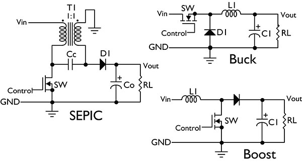
FIGURE 1.
The buck, or step-down, switching regulator converts an input voltage to a lower output voltage. When SW is closed (conducting), current builds up in L1 at a rate approximately equal to (Vin - Vout)/L1. The inductor current flows into the load (RL) and the output capacitor (C1). As the voltage across C1 rises to an upper threshold set by the regulator, SW opens and stops the input of power. However, the current in L1 still continues to flow through the rectifier diode D1, decreasing at a rate approximately equal to Vout/L1.
When the voltage across capacitor C1 falls below the lower limit set by the regulator, SW closes and the cycle repeats. The most voltage this regulator can output is equal to Vin, and that's with SW constantly closed.
The boost, or step-up, switching regulator converts an input voltage into a higher output voltage. When SW closes, current flows through L1 to ground (at a rate approximately equal to Vin/L1) and builds up a magnetic field. During this time, load current through RL is drawn from output capacitor C1. When the voltage across C1 drops below the limit set by the regulator, SW opens and stops shunting input current through L1. The current in L1 now passes through D1 and charges C1. The inductor current decreases at a rate approximately equal to (Vout - Vin)/L1, where the collapsing magnetic field causes the voltage across C1 to increase beyond that of Vin. When the voltage across C1 rises above the regulator's upper limit, SW closes and the cycle repeats.
The SEPIC regulator permits both higher and lower voltages than Vin through a unique arrangement of two coupled inductors. When SW turns on, the left plate of Cc is grounded (zero volts) and current flows through the primary of T1. This induces a voltage in the secondary, which charges Cc and provides power to the load (RL).
Each winding attempts to induce the same voltage into the other. During the off time of SW, D1 conducts, applying the output voltage to the primary winding through the secondary. This voltage induced across the primary winding happens to be the same voltage applied to it by the algebraic addition of the Vin and VCc in series with Vout + VD1.
Note that capacitor C1 provides an important function in this circuit as the chief means of energy transfer from the input to the output. The value of C1 is chosen such that the voltage across it in the steady state is essentially constant. As the voltage across Co rises beyond the upper limit set by the regulator, SW turns off, stopping the flow through T1 primary. However, current continues to flow through Cc and D1. When the voltage across Co falls below the lower threshold, SW turns on again and the cycle repeats. Depending on how much energy is stored in the capacitor and inductors, and the duty cycle of the PWM, the output voltage can be either higher or lower than the input voltage.
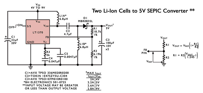
FIGURE 2.
Figure 2 shows a practical application of a SEPIC circuit. This circuit will output a constant five volts at about two amps through a range of four volts to nine volts input. You can change the output voltage by adjusting the values of R1 and R2. Linear Technology recommends R2 be less than 7K, with 6.19K the preferred value.
Comments