With Russell Kincaid
Class A/B Amp
Question:
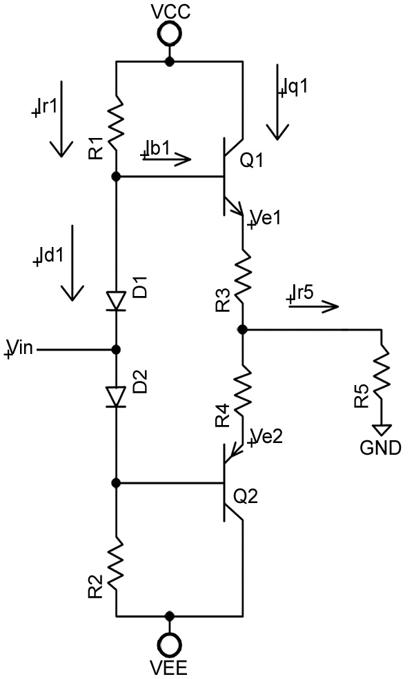
Can you tell me how the AC and DC analysis are done on the class A/B transistor amplifier (Figure 1) and answer these questions?
- Why is the signal input between the diodes?
- Does the signal voltage affect the DC bias?
- How can I use loop equations on this circuit configuration?
Sal Bivona
Answer:
This is a non-linear circuit, so you can’t do an accurate analysis without knowing the resistance values and voltages. However, you can linearize the circuit by assuming a constant 0.6 volt for the diode drop and Vbe. Then, Ve1 = Vin and the solution is trivial except that at some point, as Vin increases, the current through D1 will become zero and the output will be constant (the AC output will be clipped).
The signal input is between the diodes because it is a symmetrical circuit and you want a symmetrical output signal. The presence of input signal will increase the current output of the circuit but since DC bias is defined as the condition in the absence of signal, the question is a non-sequitur.
Since the circuit is symmetrical, analysis of the NPN circuit will also apply to the PNP circuit. The only question of interest is: Where will the output be clipped? Let us find that point.
• Since Id1 = 0, then Ib1 = (Vcc - Ve1 + .6)/R1
• Also, Ve1 = (Ib1 + Iq1)*(R3+R5)
• And, Iq1 = Beta*Ib1
• This leads to: Ve1 = [(Vcc - Ve1 + .6)/R1]*(Beta+1)*(R3 + R5)
• To simplify, let K = (Beta+1)*(R3+R5)/R1
• Then: Ve1 = [(Vcc+.6)*K] – Ve1*K
• Therefore the clipping point is: Ve1 = (Vcc+.6)*K/(K+1)
Comments