With TJ Byers
EMF Suppression
Question:
How come you sometimes put a diode backward across the relay contacts and other times you don’t? I have read that the diode is a must. What’s the real story?
Mike Edwards
Los Angeles, CA
Answer:
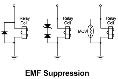
I think you’re talking about putting the diode across the relay coil, not the contacts, but they are both one and the same. When the current flow through an inductor — or coil — is interrupted, a high voltage in the reverse direction is generated by the collapsing magnetic field. This voltage can be as high as 10 times the Vcc source voltage.
If the coil is connected to a transistor or other semiconductor, the back EMF (as it’s called) can be high enough to destroy the device. The same happens across the relay contact when connected to an inductive — like a motor described in the question “Relay Contact Life” — where this creates contact arcing. This is energy that must be dissipated somehow.
A diode placed across the inductor (or contacts) will conduct when the magnetic field collapses and will effectively short circuit the voltage. The decision whether to use a diode or not depends on the voltages and currents involved. A coil with higher inductance, like a frame relay, will store more energy — both voltage and current — than will a small coil, like a reed relay. As a rule of thumb, a diode should always be included — but other factors have to be considered, not the least of which is space. If the relay is small, space is limited, and Vcc is low, I often omit the diode.
Also, placing a diode across the inductor causes current to flow longer and lengthens the hold-in time of the relay. This is unacceptable for some applications. By inserting a zener diode in series with the rectifier, hold-time is greatly reduced. This is because the diodes can’t conduct until the reverse voltage exceeds the zener voltage, plus 0.7 volts.
In some circuits, the diode(s) can be replaced with a metal-oxide resistor (MOV). An MOV behaves like back-to-back zeners and can be used in both DC and AC circuits. The choice usually boils down to available space and cost.
An ideal suppression voltage is 10 volts; that is, the back EMF should be held at 10 volts, with 15 volts as an upper limit.
In addition to arc suppression across relay contacts is the minimization of electromagnetic interference (EMI). EMI can wreck havoc with RF communications and spark the turn-on of logic gates, SCRs, and triacs.
Comments