With TJ Byers
Fun With Negative Resistance
Question:
A while back in my Circuits 101 class for Electrical Engineering, the professor mentioned something about negative resistance. This was a totally new concept to me — and he made almost no effort to explain it. It seems very strange, almost like having a negative weight or length. Can you please explain this phenomenon in more detail?
— Brian
Answer:
In electronics, this is common. In fact, it’s desirable. Without going to the math of imaginary numbers and the like, there is really no such thing as negative resistance — as in there’s no such thing as negative gravity. In both, it’s all in how you define negative.
Ohm’s Law states that as the voltage across a resistance increases, so does the current. It’s a linear function. With negative resistance, on the other hand, the current decreases as the voltage increases, as shown in Figure 1. Several devices exhibit negative resistance, including neon lamps, tunnel diodes, and Lambda diodes, which you can make yourself from a pair of Junction field-effect transistors (JFETs).
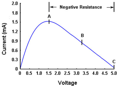
FIGURE 1.
There are two types of field-effect transistors: those that operate in the enhancement mode and those that operate in the depletion mode. Enhancement mode means that the FET is forward biased (turned on), like a bipolar transistor. Depletion mode means that the FET is reverse biased (turned off), like a vacuum tube. JFETs are depletion-mode devices.
When configured as shown in Figure 2, the two transistors interact with each other and produce a negative-resistance Lambda diode. In fact, the curve in Figure 1 are actual measurements taken from this combination. Up to point A, the current increases as the voltage is increased. At point A, the diode current peaks and begins a decline from point A to point C, while the voltage continues to increase — negative resistance!
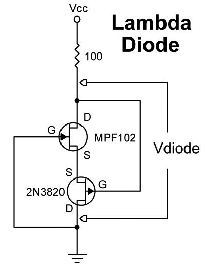
FIGURE 2.
Want to play with it? For most applications, the diode is biased in the middle of the negative-resistance slope, at point B. An example of a practical Lambda circuit is the sine-wave oscillator shown in Figure 3. All it takes is a Lambda diode and a tank circuit; this circuit should oscillate at 1 kHz with the values shown, but it can be easily extended to 100 MHz with the right tank values. The 1K potentiometer is used to set the bias of the diode because not all JFETs will land in the sweet spot at the same voltage.
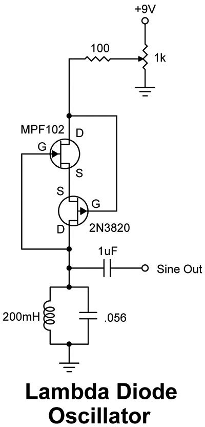
FIGURE 3.
Comments