With TJ Byers
Relay Contact Life
Question:
I am using a DPDT relay to control a 90-volt DC motor that pulls 1.5 amps under full load. The relay contacts are rated for 10 amps at 240 VAC. The problem is that the contacts have welded shut. From ancient memories, I dredged up the idea that I’d seen a capacitor used across contacts to reduce the arcing. I’ve been through most of my old electrical engineering resources and found almost nothing relating to this idea.
To calculate what I needed, I dug out the formula that I = C dv/dt. Assuming the voltage change (dv) is 90 volts, the time (dt) is 1 mS, and the current is 1.5 amps, I come up with the equation that C (capacitance I need) = 0.001(1.5/90) or roughly 1.6 mF to adequately absorb the spark. I connected a 2.2-mF, 250-volt cap across the points and it seems to be running smoothly. My question is, am I even close?
Greg Smith
via Internet
Answer:
You arrived at the right answer in a roundabout way — and by an error in your math. The answer to your equation is actually 16 mF, not 1.6 mF, yet 1.6 mF is the correct value. The rule of thumb for this method is 0.5 to 1.0 mF per amp. In your case, 1.5 amps works out to be 1.5 mF — very close to your 1.6 uF “calculation.” You were correct, though, in selecting a 250-volt capacitor for the application. The thumb rule says 200 to 300 volts.
However, there is a caution when using this method. As the capacitance increases, so does the charge and amount of stored energy that’s in the capacitor. This is energy and current that must be discharged through the contacts — at the rate of I = C dv/dt, when they close. (See where your formula comes into play?)
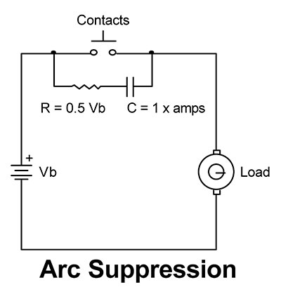
This current surge may be enough to weld the contacts and actually countermand your solution. The ideal way to suppress the arc without risking contact damage on subsequent closure is to add a resistor in series with the capacitor, as shown below. The value of the resistor is typically 0.5 to 1.0 ohms per volt — about 50 ohms, in your case. So the no-math rule is 1 mF per amp and 0.5 ohms per volt.
To express it mathematically, we need nothing more than Ohm’s Law and a capacitor charge formula. When the points separate (break), the current flow wants to keep flowing, and it will do so by striking an arc. The criteria for creating and sustaining an arc is complex, but suffice it to say that, once an arc is struck, the harder it is to extinguish because it creates its own self-sustaining environment — much like a forest fire creates its own winds to feed itself.
The conditions required to initiate an arc depend on the voltage across the opening contacts (gap) and the current at the time. Now, if we place a capacitor across the contacts, the cap acts like a short circuit when the contacts open. At this point, the cap begins to charge using the formula t = RC, where R can be calculated from R = E/I, E being the voltage across the points and I being the current flowing at the time of the break.
If we can balance the charging time of the capacitor with the time it takes for the contacts to open wide enough that the voltage can’t jump the gap, the arc is suppressed. Typically, this is 0.1 mS for a frame relay of the type you describe. Plugging these values into our equations, we get R = 90 volts/1.5 amps = 60 ohms. Calculating for capacitance, we get C = t/R = 0.0001/60 = 1.67 mF.
If you’re trying to figure out the mathematics for an AC voltage suppressor, forget it. A sine wave is self-extinguishing because it crosses zero. That is, two times every cycle, the voltage across the contacts is zero as the voltage reverses itself from positive to negative. It’s very hard to maintain an arc under these conditions — as many a welder will attest to.
Comments