With TJ Byers
“Spinnin’ Wheel Got To Go ‘Round”
Question:
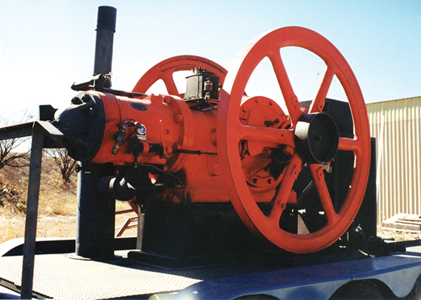
I have a 1920 model Fairbanks-Morse semi-diesel oil engine (see photo above), mounted on a three-axle utility trailer, that I frequently display at antique equipment shows and other exhibitions. This particular engine was once used to drive a river bank irrigation pump. It runs on almost anything — except gasoline (I use kerosene), hence there is no spark plug, magneto, or electrical ignition system.
Now the question: Can you draw up a circuit that would add a tachometer to this thing? The engine is rated at 325 RPM, which I usually run at 160 RPM so as not to strain anything, which is far below the range of anything I can find commercially. I'm not fussy. The readout can be LCD, LED, or an analog meter — whatever works. And the sensor can be of any type. However, I don't want to mount anything (such as a magnet) on or near the flywheel rim because it travels 35 to 40 MPH at full speed.
Thomas Earnest
San Angelo, TX
Answer:
After looking carefully at the photos you sent me, I decided that an opto-tach would be your best solution. The circuit consists of a one-shot, monostable multivibrator (upper two 4001 gates) that's triggered by a phototransistor. Each time the multivibrator is triggered, it outputs a fixed-width pulse, that's conditioned by the lower 4001 gates. This signal is then processed by an integrating circuit made up of the 1N32A diode, 5.1k resistor, and 47uF capacitor. The output of the integrator is proportional to the width of the pulse and its repetition rate. The faster the pulse rate, the higher the output voltage, which is displayed on an analog panel meter. The meter can be any 0-1 mA panel meter, such as the old RadioShack 22-410 voltmeter (sans the 15k resistor). Of course, you'll need to either create a new scale with art supplies or use a multiplication factor for the original scale. For example, in the case of the RadioShack meter, you can set full scale at 300 RMP and use a 2X multiplier to read the correct value.
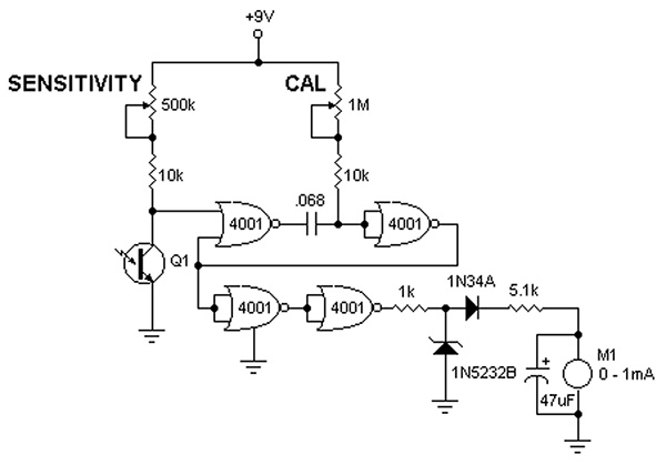
There are a number of places the phototransistor sensor can be mounted, but I had in mind mounting it behind the spokes and letting the ambient light (sunlight or incandescent lamp) act as the light source. (Don't use a fluorescent lamp for the source because its flicker will give you false readings.) As the flywheel spins, the spokes interrupt the light source six times per revolution, or about 16 times a second (16 Hz). The CAL pot adjusts the width of the one-shot pulse, and is used to calibrate the meter. The SENSITIVITY control is set so that the transistor is off when the spoke blocks the light from the source. Alternatively, you can place strips of reflective tape on the outer rim (or inner hub) of the flywheel and have the phototransistor monitor the reflected light for its trigger, thereby making the sensor less dependent on an ambient light source.
Comments