With TJ Byers
You Take the High Road ...
Question:
I’ve been a relay man all my life and I’m used to being able to switch a load in and out of a circuit in any combination I wish from any source I wish. Today, most relays have been replaced by semiconductor switches, like MOSFETs. But most designs require you connect the load to the Vcc and the MOSFET turns on the load by grounding it. Can the bottom side of the load be placed at ground instead, with the MOSFET switching the Vcc?
— James T. Kirk
Answer:
What you are asking for is called high-side switching. You are correct that most circuits use low-side switching where the load is either grounded or floating. In many applications this is not desirable for many reasons: shock hazard, sensitivity to static discharge, physically not possible (especially in auto applications), and more. Figure 1 shows the difference between low- and high-side switching.
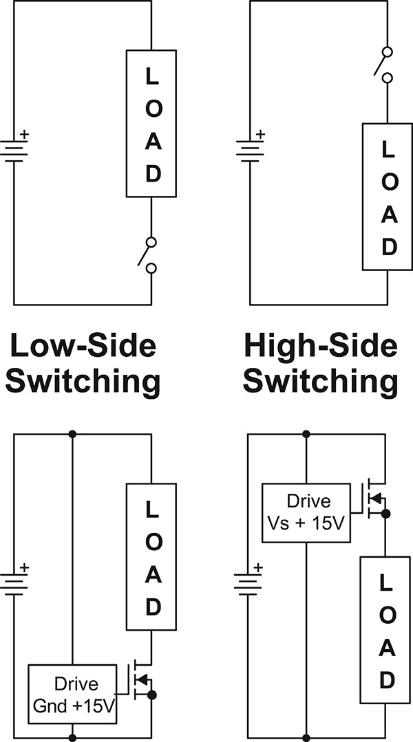
FIGURE 1.
In this figure, both the mechanical and semiconductor versions of low-side and high-side switching are shown. Flipping the mechanical switches is a no brainer, but not computer friendly. For that you need a relay — or a semiconductor switch, like the enhanced mode MOSFET or IGBT. Switching the low side is very easy, and the reason it’s the most prevalent. For details, refer to the other sections “MOSFET Basics” and “IGBT Basics.”
Switching on the high-side, on the other hand, requires the driver to ride atop ground, making reference to the MOSFET’s source terminal instead. There are several schemes used to do this, but the typical solution is to use a high-voltage driver like that shown in Figure 2. A typical IC for this application is the IR2117. Here’s how it works. The MOSFET doesn’t care where the 15 V it needs to saturate the switch comes from. For all it cares, you can slap a 15-V battery across the gate-to-source connection and it will be a happy camper.
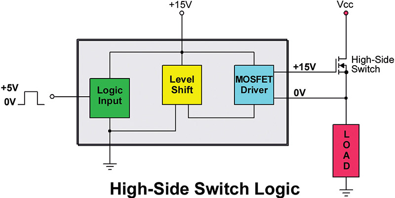
FIGURE 2.
The circuit itself is less forgiving. That is, ideally the top of the load would be at Vcc — which means that the gate voltage has to be Vcc plus +15 V before it will switch on. This is where the high-side driver voodoo comes into play. It separates the Vcc to the load from the driver circuit. The circuitry needed to do this is rather complex and must be able to withstand the voltage differential between Vcc and ground. Which is why we have high-voltage ICs like the IR2117.
If you’re working with low-power high-side switching — something on the order of three amperes or less — then the circuit in Figure 3 may suit your needs. Here the isolation between the TTL logic and Vcc high voltage is via a 4N25 optoisolator. When the 4N25 LED goes on, its internal transistor turns on and provides bias current to the PNP pass transistor and turns it on.
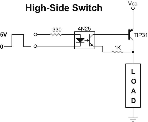
FIGURE 3.
Comments