Build an Electronic Metronome
By Paul Florian
Theory of Operation
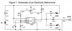
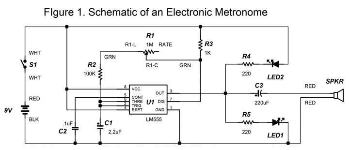
Figure 1 is the schematic for the Electronic Metronome. The design is based on a LM555 timer integrated circuit. The oscillation frequency is determined by C1, R1, R2, and R3. R1 is a 1 Megohm potentiometer and is used to set the oscillation frequency. The duty cycle is 50% and the oscillation period can be varied between 0.3 and 3 seconds. Note that the speaker “clicks” during each low to high and high to low transition. Therefore, the speaker output frequency is twice the oscillation frequency of U1. LED1 and LED2 flash alternately during each cycle of the oscillator. C3 capacitively couples the output of U1 to the speaker. The metronome circuit described here has a range of 32 to 390 beats per minute.
Construction
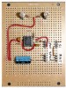
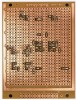
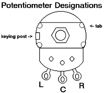
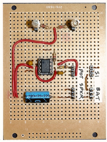
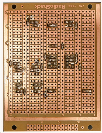
Photo 1 shows the front view of the completed circuit board while Photo 2 shows the reverse side. All of the components for this design were found in my Junkbox (with the exception of the circuit board). The circuit was assembled on a RadioShack 276-168 multipurpose PC board. The speaker I used was from an answering machine that I purchased at a thrift store for a couple of dollars. Sources for components that you don’t have can be found in the parts list. The shaft of R1 may need to be shortened. If this is case, clamp the shaft in a vice and use a hacksaw to cut the length so that 3/8" remains. Use pliers to break off the keying post on R1 (refer to Figure 2.) Be sure to use a socket for IC1. The following wire lengths are all six inches. Solder two green wires to R1: one to R1-C and another to R1-L (refer to Figure 2). Next solder two red wires to the speaker, as well as two white wires to the switch S1. These wire colors are labeled on the schematic.
When assembling the circuit board, these wires can be soldered directly to the perfboard, or they can be connected to a female crimp housing connector that mates with .100” male headers soldered to the board. The wires described earlier are interchangeable. For example, the speaker wires can be switched when connecting to the circuit board. However, the battery wires are polarized and can only be connected one way. When assembling the circuit, be sure to observe polarity on capacitor C1 and the LEDs. The positive wire of C1 is marked with a “+” sign near one lead of the capacitor. This lead corresponds to the “+” sign on the schematic. C3 has the negative lead marked with an arrow. The other lead is positive, analogous to the “+” sign on the schematic. The bar on the LEDs shown on the schematic is known as the cathode. This corresponds to the lead located next to the flat side of the LED.
Testing
After the circuit is assembled, verify that S1, the battery, the potentiometer, and the speaker are connected to the circuit board. Do not install U1 in its socket yet. Attach a 9V battery to the battery snap. Turn on S1. LED1 and LED2 should both illuminate. If this is not the case, check that the LEDs are installed with proper polarity. Next measure the voltage at U1 pin 4 and U1 pin 8 with reference to ground. The voltage in each case should read 9V. Turn off S1 and install U1 in its socket. Then turn on S1. Verify that the LEDs flash alternately and the speaker clicks with the oscillation frequency determined by the rotation of the potentiometer. If these results are not obtained, double-check the installation of the components connected to U1.
Final Assembly
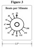
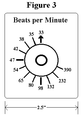
Once the circuit checks out, find a suitable enclosure to install the PCB, speaker, potentiometer, on-off switch, and battery. Cut out the label in Figure 3 and affix it to the case with the arrow pointing up. Then install R1 through the center of the label. Following this, turn the shaft completely clockwise. Next attach the knob to R1 so that the white stripe points up. The unit is now ready for operation. Have fun building and using your Electronic Metronome!

 FA_1008_metro_Parts_List.pdf
Comments

