An Intro and Antennas
By H. Ward Silver
I’m thrilled to help return ham radio to the pages of Nuts & Volts! In every other issue, I’ll be discussing some aspect of ham radio technology that you can use on your workbench and in your projects — whether you have (or get!) a license or not. Over the years, NV has featured ham radio in articles and columns so ham radio was never truly absent. The magazine’s editor is a ham (NU1N) and Paul Verhage — maven of the high altitudes and Near Space columnist — is also known as KD4STH. Many of the authors hold an amateur “ticket,” so maybe they will share their call signs with us in future articles. You may be surprised at how widespread amateur radio really is!
A little about my background: I have a degree in Electrical Engineering and spent 20 years in various types of industrial and medical product development — both hardware and software. I’ve had an amateur radio license since my high school days and am now known on the ham bands as NØAX (the slash is silent). For the last dozen years or so, I’ve been writing and editing books and columns for the American Radio Relay League (www.arrl.org), such as the three licensing study guides; a classic reference for radio technology, The ARRL Handbook; and a nearclassic antenna reference, The ARRL Antenna Book.
Some of my other books and columns are included in the sidebar on resources, including Ham Radio for Dummies. I’m pretty active on the air and like to operate in competitive events known as radiosport, as well as provide public service and study radio wave propagation. There is more on my “ham radio bucket list” than I will ever get to!
So, what is this ham radio stuff anyway and why should you care? First, there is far, far more to amateur radio in the 21st century than in the movies. Those images you see of glowing tubes and racks full of black crinkle-finish equipment with the jumping meters and dials? They are as obsolete as 8” singlesided floppy disk drives and 7400 family TTL logic! Sure, some of that gear is still out there on the air, but today’s ham radio is up to date and innovative.
Hams are big players in the Arduino and Raspberry Pi communities, just as they are in developing over-the-air digital communications protocols and networks. Even if you’re not really interested in the full ham radio experience, you might be interested in using non-licensed wireless data links in your projects, for example. Whatever your specialty, learning about radio will help you select, apply, and use wireless technologies better.
Modern-day ham radio is really a combination of three important components. The first is science: Hams learn about radio circuits and systems, antennas, how signals propagate from place to place, and the antennas that make it happen. The second is skill: By practicing effective operating, hams apply that science to insure that signals get from point A to point B. Finally, the ham combines the science and skill in service of his or her fellow citizens. You may have seen the motto “When All Else Fails,” which refers to the ham’s storied ability to fill in when commercial and government communications are disrupted.
All three aspects — science, skill, and service — are important, and there is a home for you in whichever area is most interesting.
This column will touch a lot of bases: antennas, transmission lines, batteries, digital protocols, radio frequency (RF) circuits and techniques, test equipment, and the list goes on. We’ll discover that components act a lot differently above a few megahertz (MHz) than they do at audio and DC. I will show you how to install those pesky feed line connectors so the signal goes to the right place.
Similarly, we’ll take a look at ways to keep RF signals from leaking out of and getting into your equipment. In some columns (like the one this month), there will be an experiment or activity you can do to gain valuable experience and maybe even a useful gadget. Ready to get started? I thought so!
The Ground Plane Antenna
There is no subject better suited to kick off a column about ham radio technology than antennas. All forms and specialties of ham radio share antennas as a common part of the station. If it’s ham radio, you can be sure of an antenna being involved. Actually, a lot of non-amateur electronics also deal with antennas, such as wireless links and mobile phones.
 |
 |
|
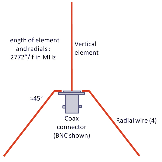
Figure 1. Basic ground plane construction showing the formula for the length of the vertical element and radials.At least two radials are required; four are recommended, and should be arranged symmetrically around the vertical element. |
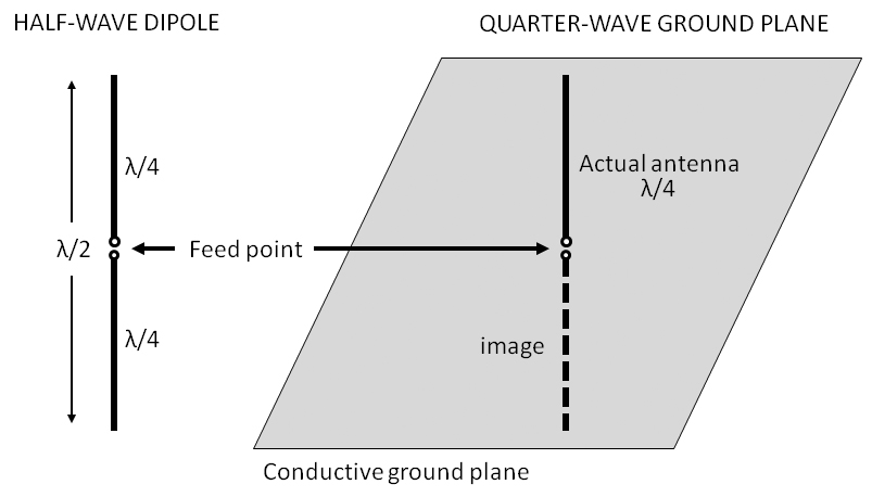
Figure 2. The quarter-wavelength long ground plane antenna behaves similarly to a half-wavelength long dipole antenna with two quarter wavelength halves. It uses a solid conductive sheet or radial wires to supply the same effect as that of the “missing” quarter-wavelength. In this column, I’ll introduce you to one of the simplest antennas and show you how to make one to use at home — or even design your own.
|
Figure 1 shows the basic idea: A vertical wire is attached to the center conductor of a coaxial cable connector, and several radial wires are attached to the mounting holes of the connector. This particular style of connector is called a receptacle or panel jack because it is designed to mount on a panel and have a cable attached to it. (Bulkhead receptacles mount with a nut and lock washer in a single hole, and won’t work for this particular antenna.)
A family of connectors shares common attachment mechanisms and body sizes. The receptacle we’re using here is from the BNC family. (Other common connector families include SMA, N, and UHF.)
The vertical wire — called an element — is the main part of the antenna that receives the signal. Does the orientation of the element matter? Yes, it does. Radio waves are made up of an electric or E field and a magnetic or H field that are at right angles to each other.
The magnetic field makes electrons move in tight little circles which is not very useful in creating currents that flow to a receiver. The electric field, however, makes electrons move in a straight line. In this case, the antenna is designed so the E field will make the electrons move back and forth along the wire element, into the coaxial cable, and down the cable to the receiver.
The orientation of the electric field determines the radio wave’s polarization — horizontal or vertical.
When the antenna element and radio wave E field are aligned, the antenna receives the strongest signal. The orientation of the antenna’s element or elements determines the antenna’s polarization. In this case, the antenna is vertically polarized. Since the NOAA Weather Station broadcasts that this antenna is designed to receive are transmitted by a vertically polarized antenna, our antenna should be vertically polarized to receive the maximum signal. (Misalignment is called crosspolarization and can result in up to 99% or 20 decibels [dB] of signal loss because the E field no longer makes electrons move along the antenna element as receivable current.)
An Electrical Mirror
The name “ground plane” comes from the four radial wires — so-called because they extend radially from the center. The ground plane acts as an electrical mirror to create an electrical image of the antenna’s missing half. Missing half? Yes, the ground plane antenna is actually one-half of a dipole as shown in Figure 2.
The mirroring effect of the ground plane is the same as that of the missing part of the dipole. In this case, four radials are enough to do the job. For ground plane antennas mounted on vehicles, the radials are replaced by the sheet metal of a roof or trunk.
A one-half wavelength long dipole is an effective antenna that radiates and receives equally well in all directions around the antenna’s axis. If the dipole is vertical, the equal response from any direction makes it omnidirectional.
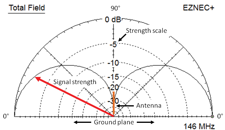
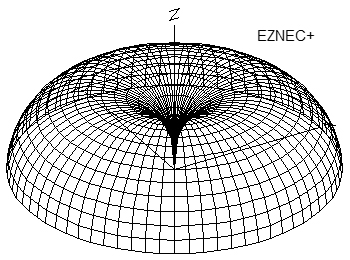
That omnidirectional response is not repeated if one looks at the antenna’s response from the side. Figure 3A shows the ground plane’s elevation pattern starting at the horizon (0°) on one side, going over the top of the antenna (90°), and back to the opposite horizon. The antenna receives very little signal overhead because the E field of a radio wave coming from that direction only moves an electron back and forth across the element, not along the element where it becomes a current that can be received.
 |
 |
|
Figure 3A. These are radiation patterns showing how strongly an antenna responds to signals arriving from various directions.The distance from the center to the solid line shows the strength of the response in decibels with respect to the maximum response.This figure shows an elevation pattern looking at the antenna from the side. |
Figure 3B. The threedimensional pattern resembling a bagel with the antenna at the center.The patterns were generated by the EZNEC antenna modeling software (www.eznec.com). |
The notch in the antenna’s pattern is called a null, whereas the region of maximum response at the horizon is a lobe. An azimuth pattern would look down on the antenna from the top and show how well the antenna receives in all directions or azimuths. Since the antenna is omnidirectional, that pattern would be a simple circle.
Figure 3B shows what the antenna’s three-dimensional response looks like — sort of a bagel shape if the antenna was stuck through the middle.
By replacing the lower half of the dipole with its image, the quarterwave ground plane achieves the same effect of a vertical dipole, but in a smaller package with easier mounting. Ground plane antennas are common at frequencies from the AM and long-wave broadcast bands (at and below 1.7 MHz), all the way up to about 1 GHz wherever an omnidirectional response is desired.
A Ground Plane Antenna for NOAA Weather Stations
Many scanners and VHF radios have the ability to receive the seven NOAA weather station channels near 162.5 MHz (www.nws.noaa.gov/os/marine/wxradio.htm). The flexible whip (also known as “rubber duck”) antennas provided with portable radios are not very efficient. If you are in an area of weak coverage or are traveling to a remote area, you may need a full size antenna to pull in these stations. By building this simple ground plane antenna, you will be able to receive more of the stations over a wider area.
Parts List and Instructions
• Six foot BNC-to-BNC coaxial cable (RG-58 or RG-8X cable)
• BNC panel jack (UG-290 style or any flange-mount style)
• Eight feet of #14 AWG solid copper wire or brass rod (#12 to #16 will work and stand up to handling)
• Four ring crimp terminals for 12-16ga wire (blue insulation) for #4 stud
• #4 hardware to attach terminals to connector flange
Start by calculating the length of wire for the vertical element and the four radials. All five will be the same length. Use this equation with a frequency of 162.5 MHz:
L (inches) = 2772 / f (MHz) = 2772 / 162.5 = 17.1 inches
Where does the equation come from? Remember that the ground plane’s vertical element is one-quarter wavelength long or λ/4, where the Greek letter λ stands for wavelength. In free space at the speed of light, λ = 300 x 108 m/sec / frequency or λ/4 = 75 / frequency in MHz. Converting to inches, λ = 2798 / f (MHz). So, why are we using 2772 instead of 2798?
 |
|
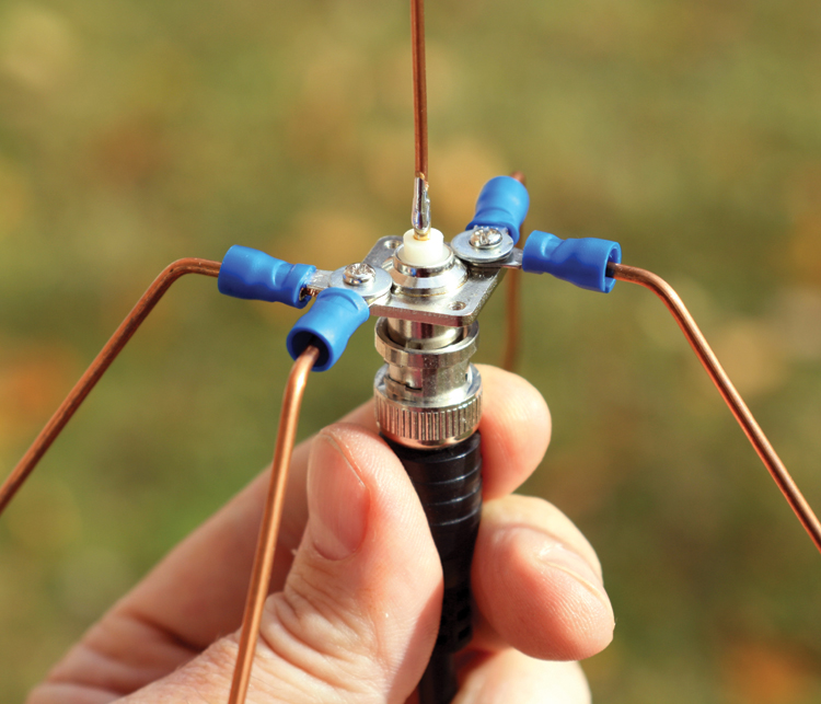
Figure 4. Close-up of the assembled ground plane showing one method of attaching radial wires to the BNC connector flange. Radials may be attached permanently by soldering, or temporarily with screws. |
The speed at which a radio wave travels along a piece of wire is slower than in air or the vacuum of free space. That makes the wire act electrically longer than its physical length. In other words, λ/4 is shorter when the wave is traveling on a wire than it is when the wave is traveling in free space. The thicker the wire, the slower the wave travels. This is called the length-to-diameter (l/d) effect and it must be accounted for when determining the length of antenna elements. For #14 wire, the l/d effect results in the use of 2772 instead of the free space value of 2798.
Cut five pieces of wire. Crimp a terminal onto one end of four of the pieces. Solder the remaining piece of wire to the BNC receptacle’s center pin. Attach each radial to the receptacle with the #4 hardware.
Figure 4 shows one way to do it. Bend the radials down (away from the vertical element) about 45 degrees and arrange them symmetrically around the receptacle. Attach the coaxial cable to the antenna and the radio – you’re done! Figure 4 is a close-up of the antenna’s feed point where the feed line is attached. (If your radio uses some other type of
connector than BNC, you’ll need to use an adapter.) If your radio has a signal strength meter, compare your new antenna to the flexible antenna provided with your radio. Why are the radial wires bent at an angle when Figure 2 shows the ground plane as flat? If the radial wires (or conductive sheet) are at right angles to the vertical element, the feed point impedance of the ground plane will be about 35W which is different than that of the coaxial cable (which is usually 50W). This mismatch will make it harder for signals in the vertical element to transfer to the coax, and reduces the effectiveness of the antenna a bit.
By bending the radial wires down, the feed point impedance is raised closer to 50W. (Cable impedance will be the subject of a future column.)
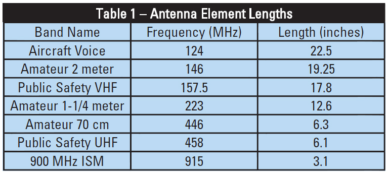
Your antenna will perform well over a fairly wide range of frequencies that are up to ±5% from the design frequency. Table 1 shows the wire length for several commonly monitored radio services. Assuming you don’t want to hold the antenna up in the air with one hand when you want to use it, you can simply tape the supporting cable to a piece of dowel, pipe, conduit, or whatever is handy. Secure the support so the antenna is in the clear and at least l/2 away from any other metal surface or object.
 |
I hope you’ve enjoyed this first installment of The Ham’s Wireless Workbench and will be a regular reader as we explore the world of ham radio technology. Visit the ARRL website and read what’s there — you’ll learn a lot and maybe I’ll eventually hear you on the air with your own call sign!
Until then, 73!
(That’s the ham’s shorthand for “best regards.”) NV
|
Radio and Radiation |
|
The word “radiation” tends to get people excited because the same word is used to apply to all types of radiated energy — from radio waves to infrared light to X-rays and atomic particles. Radio waves as we are discussing here are non-ionizing, meaning they do not have enough energy to knock electrons away from atoms creating ions. The only effect from radio waves on humans is thermal or heating. For radiation to become ionizing, it takes extreme ultra-violet, X-rays, gamma rays, or particles to create ions and cause chemical changes in cells. For more information on safety issues associated with radio waves or RF, see [url=http://www.arrl.org/rf-radiation-and-electromagnetic-field-safety]http://www.arrl.org/rf-radiation-and-electromagnetic-field-safety[/url]. |
|
Where Does the Term “Ham” Come From? |
|
Everybody wants to know why it’s called “ham” radio. While there are many answers floating around, the truth is that no one really has the definitive answer. Nevertheless, after being asked thousands of times, the most common and reasonable source of “ham” is that it was originally a not-very-complimentary term used to refer to the amateurs by commercial and military operators. In those days of spark transmission — the original ultra-wideband signal! — everybody had to share all of the radio spectrum, so interference was a huge problem. The amateurs turned the term into a badge of pride that persists to the present day. It’s not an abbreviation for anything, so it’s never capitalized. It’s referring to the original hackers — the hams. |
|
Your Go-To Source for Radio Know-How – the ARRL |
|
The world’s oldest amateur radio organization is also the United States’ national amateur radio institution: the American Radio Relay League, or the ARRL ([url=http://www.arrl.org]http://www.arrl.org[/url]). Usually referred to by hams as “the League,” the ARRL’s motto is “Of, By, and For the Amateur.” It represents amateur radio internationally and in Washington, D.C. to insure that hams have the necessary spectrum to fulfill the amateur service’s role.
Within the amateur radio community — more than 700,000 in the United States alone — the ARRL’s role is to educate amateurs, support the volunteers who perform all licensing activities, and provide training and service activities to keep the skills of hams sharp and ready.
The ARRL publishes an enormous amount of technical and operating material in whatever area of amateur radio is most attractive to you. If you would like to explore some of the technology resources on the ARRL website, there is a special portal just for you at www.arrl.org/tech-portal. |
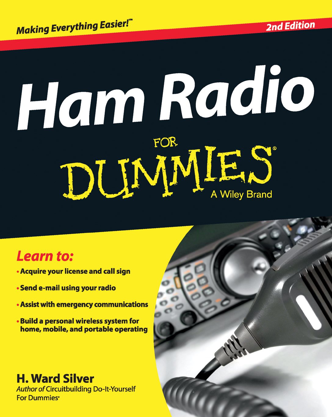 |
Ham Radio for Dummies, Second Edition (Ward Silver NØAX) — An introduction to ham radio that explains what it is and how it works in bite-sized chunks. |
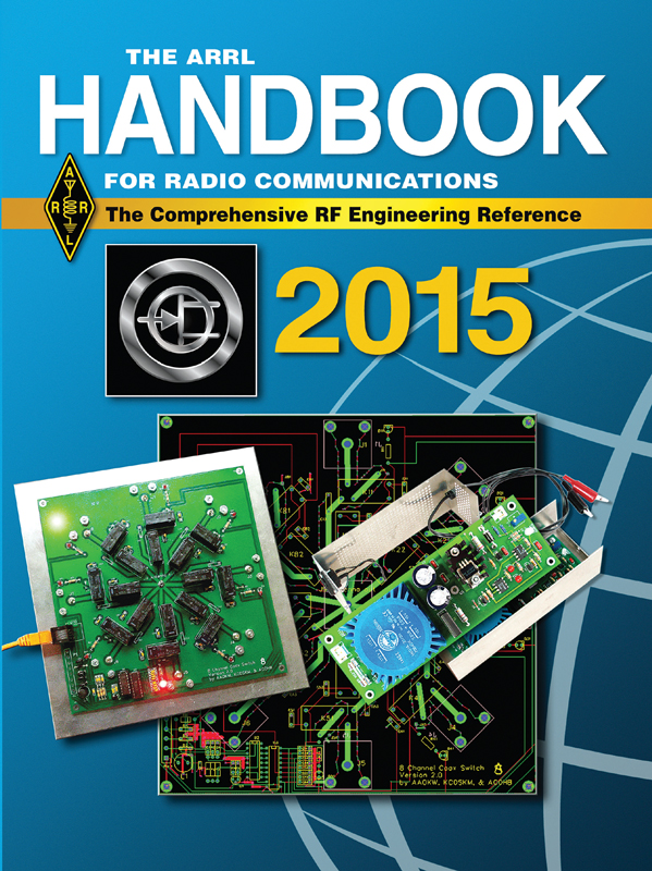 |
ARRL Handbook — Now in its 92nd edition, “the Handbook” covers nearly all areas of amateur radio technology from tutorials in basic electronics to the latest digital protocols and equipment innovations. See the ARRL Store (http://www.arrl.org/shop/technical) for a long list of technical books. |
College students and educators will want to bookmark the web portal that supports university level ham radio interests at http://www.arrl.org/college-students-and-educators.
Comments