Bling Up Your 4th Of July With A Set Of Custom SMT Earrings
By Ron Newton
 Since the Fourth of July is coming, I thought this would be the perfect time to introduce some new designs for other holidays and occasions, except this time I would make the earrings adaptable. These new circular versions include fireworks, a Jack o’ lantern for Halloween, and the timeless happy face that can actually change expressions — sad, happy, mischievous, winking, surprised, disapproving, etc.
The three versions discussed here will all use SMT components. It really won’t be too difficult, and you won't need a reflow oven.
 |
 |
 |
| Fireworks |
Jack O'Lantern |
Emoticon |
One thing I want to bring your attention to is a new tool which I think is a must-have for working with SMT. Surface-mount capacitors don't have markings and are easy to get mixed up if spilled. Our friends at SparkFun have released a new combo set with a probe and tweezers that attach to multimeters. They work fine from 1206 to 402 SMT components. When connected to the diode mode of a DVM, you can easily discover the cathode of an LED. Place it on a capacitance meter and instantly you’ll see the unknown value of a capacitor. It works well with components on a board, as well. These cool units sell for under $6.
The fireworks adaptation starts out as a sputtering fuse, shoots up in the sky, explodes, and then turns red, white, and blue. Next, it displays all three colors together, and finally sputters out.
The Jack o’ lantern has flashing red eyes and its face changes. Maybe next time, I will make him giggle with a sound board.
The emoticon earring can be like a mood ring. Or, you could even use it as an IQ test for people to figure out how you’re feeling. Emoticons can be dated back to the 19th century and are used throughout the world. In Japan, they are known as " kaomoji." The "smiley face" was drawn in 1963 by Harvey Ball and is still popular.
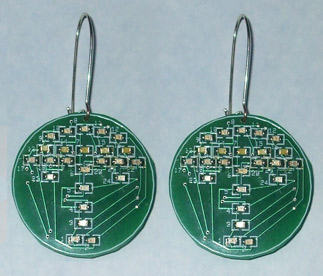
All three sets of earrings measure 1.3 " in diameter and are round. They weigh five grams, including the battery. Each earring uses a CR1225 lithium battery which should last for many hours.
The three sets of earrings have 24 LEDs set to patterns (the Jack o’ lantern only uses 19). The earrings employ 805 LEDs and let the mind connect the dots Believe it or not, they are not all on at the same time but are multiplexed, giving the appearance otherwise. Eight ports provide the positive voltage to the LEDs, and three ports switch their cathodes to ground. By alternating the ground and the positive output, you only need 12 ports to drive the 24 LEDs.
The boards were drawn using ExpressPCB free software (www.expresspcb.com) and can be found on the Nuts and Volts website download. N&V has a complete kit with pre-programmed microprocessors which make it easy for the novice to put together. Make sure you check the website's "Hints and Tips" for any errata. The ASM files are also located there.
You will need a small tipped soldering iron with fine solder, a pair of tweezers (I use curved), and small solder braid for solder bridges (if any). There are no holes to drill.
HOW IT WORKS
Refer to the schematic in Figure 1. It is a general schematic for all three versions. As mentioned, the Jack o’ lantern only uses 19 LEDs. The microprocessor is the heart of the project and runs at 4 MHz. For each earring style, it uses a progressive code to tell which LED to turn on and which ones to turn off. Eight 150 ohm resistors limit the current to the LEDs.
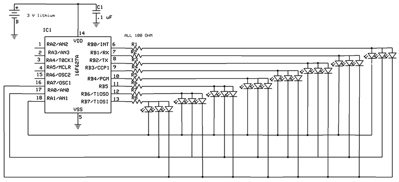 |
| FIGURE 1. General schematic for all three versions |
I used a Microchip PIC16F627A. It can sink/source 25 mA per port and up to 200 mA for the whole chip. It has 18 pins and is known as an SOIC mount, which keeps it small but very easy to solder. Since the LEDs are limited to 20 mA, this is actually ideal since it eliminates the need for extra transistors for the control circuit which just adds voltage drops. Running at three volts, a current-limiting resistor will hold down the current to the LEDs to below 20 mA when pulsed. You do have to be careful about picking the LEDs, though. I made the mistake of using the cheapest white versions I could find, only to discover that it needed 3.6 volts to function.
Once an LED is called to be turned on, its cathode is grounded and a positive voltage is applied via a resistor to its anode. In the programming, I use the general call, "Call Clear" which resets all the cathodes and anodes to ground. This insures all the LEDs are off. The next LED is then turned on, and so on, and so forth.
The LEDs turn on and off at approximately 6.6 kHz — well above 60 Hz, which is the persistence of vision (refer to the December 2014 issue for more discussion of this phenomenon).
BUILDING THE EARRINGS
GENERAL
Use a one inch strip of double-sided tape and place it on the bench. Stick a board to the tape. I use another piece of tape for placing the surface-mount components on, so I can orient them. I recommend Tacky flux to hold the LEDs on the board. I'm presently using "Quick Chip Tacky Flux" SMD4300TF which is water soluble. When placing an SMT on a board, I don't use any solder as there is usually enough on either the component or pad on the board to tack the SMT. Hold the component with a pair of tweezers and touch the soldering tip to both the component and the pad for about three seconds. I actually tacked all three types of earrings without using any extra solder. Make sure the tip is clean.
Now, turn the board 180 degrees and using solder, touch the tip to both the component and pad, and add a small amount of solder to the tip. Use the solder sparingly. If you get too much, use solder braid to remove any excess.
Turn the board 180 degrees and solder the tacked side to complete. Always rotate the board to make soldering easier. Don't try to reach over the components as it can become a disaster.
FIREWORKS EARRINGS
 |
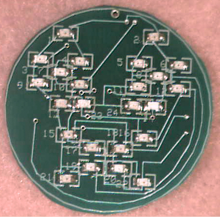
| FIGURE 2. Fireworks LED placement |
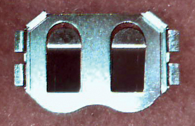 |
| FIGURE 3. Battery Holder |
Although the silk screen on the board lists the LEDs, it is small and hard to read. Check out Figure 2 to get a better look at the boards. Be sure and follow the parts list for the colors of the LEDs. You can start with any number, but I recommend keeping things in order starting with number one. All cathodes (normally, a small line is on the front or back of the LED) will be toward the left, or next to the number of the LED. Use the general guidelines mentioned previously for soldering these LEDs.
Turn the board over and tack the single capacitor (it has no polarity) and the eight 150 ohm resistors. Finish soldering these components. Next, tack the microprocessor. There is a little indented dot on the micro indicating pin 1. Make sure this goes to pad 1 on the board. There is normally enough solder on the pads and the micro, so you don't need to add solder. Inspect with a loupe to insure proper soldering. Add solder sparingly to each pin and pad. If you get a solder bridge, use solder wick to remove any excess. (Most beginners use too much solder.) Finally, solder the battery holder. Make sure the stopping ears of the holder are toward the center of the board and not the edge. Otherwise, you won't be able to put in the battery (see Figure 3).
JACK O’ LANTERN EARRINGS
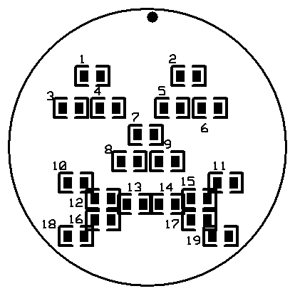
Refer to Figure 4 and the Parts List. Recall there are only 19 LEDs on this board. Follow the general instructions for the fireworks earrings.
EMOTICON EARRINGS
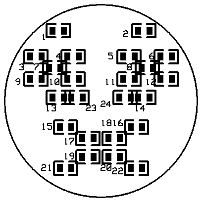
Refer to Figure 5 and the Parts List. Again, follow the general instructions discussed above.
 |
 |
| FIGURE 4. Jack O' Lantern LED placement |
Figure 5. Emoticon LED placement |
NOTE: All the LED cathodes will be facing left with the exception of # 23 which will be facing to the right. (This board is like trying to get 10 lbs of potatoes in a 5 lb bag.) This LED was reversed because I ran out of board space for traces. It was easier to reverse the diode than to design a multilayer board which can get expensive.
USING THE EARRINGS
There is a small hole at the top to attach the earring wires or clips. Just add a CR1225 battery and the earrings should light and perform on their own. A couple of things can cause havoc (speaking from experience). An LED being reversed or shorted can cause other LEDs to light up that should not be lit. LEDs that are cold soldered can do the same thing.
POWER CONSUMPTION
When an LED is on, it is pulsed about 30 milliamps. Only one LED is on at a time, so the micro draws a minimal amount of power (less than .1 milliamps). However, the LEDs are not on 100% of the time and depending on the earring type, some sit silent for a period of time. The CR1225 has 25 mAh of power. If one LED was on 100% of the time drawing 15 milliamps, the battery would power it for 3.2 hours. I would expect at least eight hours of operation.
FOR THE BRAVE AND BOLD
For most of my projects, I add pads for anyone who wants to change the programming. Unfortunately, there was not enough room on the board for the pads. However, it can still be programmed via soldering wires (I use wire-wrap wire) to the programming pins, ground and Vcc. A total of five wires are needed. These wires go to a PICkit 2 or 3 programmer. This is how I set up the faces and the fireworks.
As a final check, I grounded one column and turned on each resistor separately, noting which LED turned on. Then, I grounded the second column, etc. Worksheets with the codes and LED numbers for the different versions are on the website since each earring has a different pattern to follow.
Now, you can truly put on a HAPPY FACE! NV
Parts List
|
| Component |
Qty |
Description |
Mouser Part Numbers |
| EMOTICONS |
| Battery Holder |
1 |
12 MM battery |
712-BAT-HLD-012-SMT |
| C1 |
1 |
.1 uF 805 |
C0805C104K5RACTU |
| IC1 |
1 |
PIC16F627 SM |
579-PIC16F627A-I/SO |
| Leds 1-2-15-16-17-18-19-20-21-22 |
10 |
Red 805 |
859-LTST-C171CKT |
| Leds 3-4-5-6-7-8-9-10-11-12 |
10 |
Yellow 805 |
859-LTST-C171KSKT |
| Leds 13 -14-23-24 |
4 |
Blue 805 |
859-LTST-C171TBKT |
| R1 - R8 |
8 |
100 ohm 805 |
RK73H2ATTD1000F |
| 12 MM BATTERY |
1 |
CR1225 |
|
| Ear Wires |
1 |
See local craft store |
|
| FIREWORKS |
| Battery Holder |
1 |
12 MM battery |
712-BAT-HLD-012-SMT |
| C1 |
1 |
.1 uF 805 |
C0805C104K5RACTU |
| IC1 |
1 |
PIC16F627 SM |
579-PIC16F627A-I/SO |
| Leds 3-4-5-6-8-9-10-11-12 |
9 |
Red 805 |
859-LTST-C171CKT |
| Leds 1-2-23-24 |
4 |
Yellow 805 |
859-LTST-C171KSKT |
| Leds 17-18-19-20-21-22 |
6 |
Blue 805 |
859-LTST-C171TBKT |
| Leds 7-13-14-15-16 |
5 |
White 805 |
593-VAOL-S8WR4 |
| R1 - R8 |
8 |
100 ohm 805 |
RK73H2ATTD1000F |
| 12 MM BATTERY |
1 |
CR1225 |
|
| Ear Wires |
1 |
See local craft store |
|
| JACK O'LANTERN |
| Battery Holder |
1 |
12 MM battery |
712-BAT-HLD-012-SMT |
| C1 |
1 |
.1 uF 805 |
C0805C104K5RACTU |
| IC1 |
1 |
PIC16F627 SM |
579-PIC16F627A-I/SO |
| Leds 1-2-3-4-5-6 |
6 |
Red 805 |
859-LTST-C171CKT |
| Leds 7-8-9-10-11-12-13-14-15-16-17-18-19 |
13 |
Yellow 805 |
859-LTST-C171KSKT |
| R1 - R7 |
7 |
100 ohm 805 |
RK73H2ATTD1000F |
| 12 MM BATTERY |
1 |
CR1225 |
|
| Ear Wires |
1 |
See local craft store |
|
Click Here to download Express PCB, code, schematic, and LED placement files for this project.
Click Here to go to the Nuts & Volts webstore and get the kit or see the ultra low production quality video.
Comments