Combining utility and electronics education suggests use of a simple temperature sensor that produces a linear (straight-line) voltage output as temperature changes. The TMP36 sensor, for example, produces about 0.3V at -25°C to about 1.5V at 100°C (boiling water). I recommend the TO-92 3-pin package that will unobtrusively go in a refrigerator.
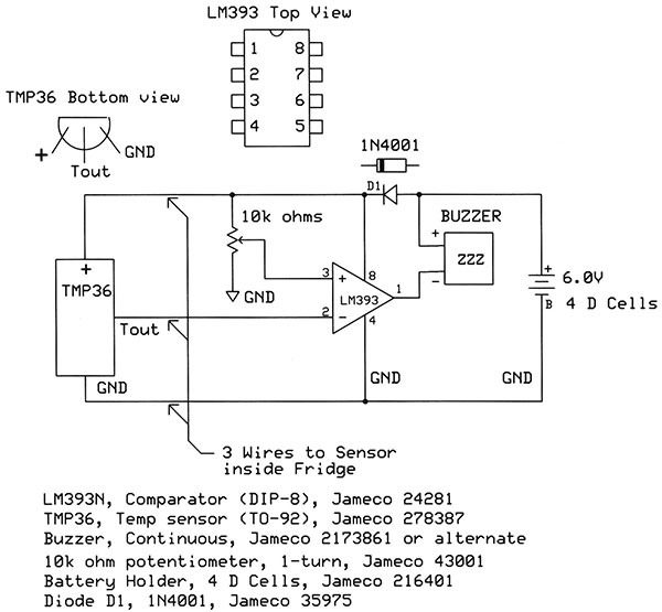
The three connections are power (pin 1), temperature-voltage output (pin 2), and ground (pin 3). The sensor provides a learning opportunity because you can use a simple voltmeter to measure the temperature in your refrigerator and experiment with ice water, hot tap water, and so on. Just solder three wires to the sensor and apply power. Use heat-shrink tubing to insulate the bare leads on the LM36 and the solder connections. A few dips into clear nail polish help with waterproofing.
The slope of the TMP36 output voltage amounts to 10 mV/°C, with a 500 mV offset. Thus at 1.5°C, the temperature of an "average refrigerator," output should read 615 mV, or 500 mV + 15 mV. At 100°C, you should measure 1.500 volts. Just remember to subtract the 0.500V offset if you calculate a temperature from the sensor's voltage output. Don't worry about the exact voltage: The sensor has a typical tolerance of ±1°C.
To turn on an alarm when temperature increases beyond a specific point, an analog comparator does the job. The LM393 offers a good example. You get two comparators in an 8-pin dual inline package (DIP) but use only one for the fridge monitor. The second comparator stays unconnected. The LM393 has two inputs, Vplus (pin 3) and Vminus (pin 2), and one output (pin 1). The IC takes power at pin 8 and connects to ground with pin 4. When Vplus > Vminus, the output becomes a logic-1. When Vplus < Vminus, the output switches to a logic 0, basically a connection to ground. This latter condition acts like a switch to ground and it lets the comparator control a small piezoelectric buzzer connected between the power supply and the comparator output. (Or you could use an LED as a visual indicator.)
To use the comparator, connect the Vminus input to the LM36 sensor output. Connect the Vplus input to a variable resistor--10K ohms will work well. This resistor lets you set the "trip" voltage between ground and the power supply voltage. Adjust the resistor to the point where the buzzer just turns on or just turns off. Then make a slight adjustment in the direction that turns the buzzer off. This change gives the comparator a reference voltage at the comparator's Vplus input. When the sensor voltage exceeds this "set point" voltage, the buzzer turns on.
PUI Audio and Mallory Sonalert manufacture loud piezoelectric buzzers. Choose one in your hearing range. AQll Electronics has a loud siren (ES-25) that operates from 6V and will alert everyone in your house to the open fridge door! You can create a circuit on a piece of solder breadboard. Try the SB300 Solderable PC Breadboard available via Amazon.
For power use four D dry cells. A diode in the circuit drops the voltage from 6 to about 5.3 volts. That's within the range of recommended voltages for the LM36 sensor.