There is a wide assortment of voltage regulators available today, both linear and switching styles. The switching regulators are generally more efficient, but the question is about a linear regulator so I will stay with that.
Three concerns are brought into this question: reliability, efficiency, and accuracy. And it appears that this is going to be used with a battery.
First, a battery, by itself, is a fairly well regulated source. But there are two problems that are generally of concern with using a battery by itself. First, it may be hard to get a battery voltage that is what the circuit needs. For instance, if you are using 5V logic chips, then you are not going to find a 5V battery.
Second, the battery voltage will decrease with use: it will run down. This may not be desirable. But many logic circuits as well as many linear ones can run very nicely on bare battery power. CMOS logic chips can use supplies over a wide voltage range, so a 6 or 9V battery can be a good choice.
If you don’t really need a constant voltage over the life of the battery, a series resistor or diode can drop a fixed amount of voltage to bring the battery voltage down to the level needed by the load. But that voltage to the load will change as the battery runs down.
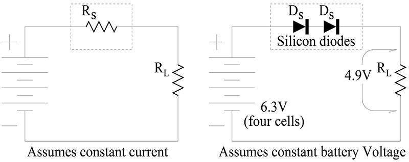
Figure 1
Linear regulators are of two general types, series and shunt. The series, linear regulator uses a series resistance that is controlled in a manner so that it drops the excess voltage from the voltage source, leaving only the amount desired for the load. The shunt regulator has a fixed, series resistance and diverts or shunts enough current to ground to bring the load voltage down to the desired value.
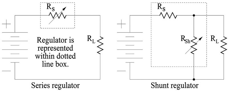
Figure 2
Another thing that must be considered when discussing efficiency is the amount of current that the regulator circuit itself needs for it’s operation. So, for instance, the series regulator circuit actually looks more like this.
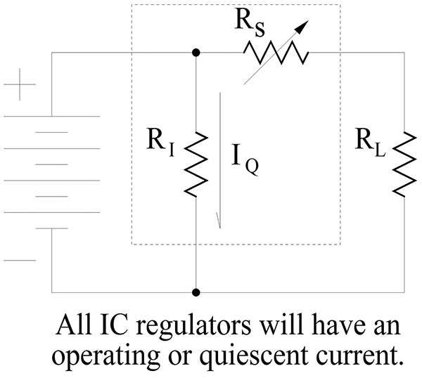
Figure 3
Assuming that a regulator is needed and sticking to linear types, there are several choices, including the zener diode and IC types mentioned in the question. A zener regulator is a very simple form of voltage regulator. The circuit looks like this:
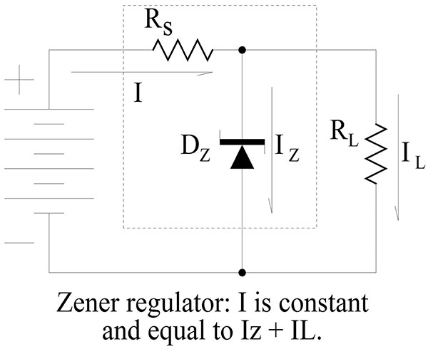
Figure 4
The theory is simple, the voltage drop across a zener diode will be constant so the series resistor drops the remainder of the supply voltage and allows the amount of current needed for that condition. The thing to notice here is that the voltage drop across the series resistor is approximately constant if the supply (battery) voltage is constant. So, according to Ohms law, the current through the series resistor is also constant. That current is the total current in the circuit and it is divided between the load and the zener diode.
The design of a zener regulator works like this:
- Find the MAXIMUM load current that will be needed. It is important to find the maximum value, because if the current ever exceeds this value, the zener regulator will drop out of regulation and the voltage across the load will be lower than the design value. This is IL.
- From the data sheet for the zener diode, find the quiescent or lowest operating value of current that is needed for the diode to operate at the zener voltage. This is Iz.
- Add IL and Iz together to get the total operating current. I = IL + Iz
- Rs must drop the difference between the battery voltage and the desired load voltage. Vs = Vb - VL. And, again using Ohms law, Rs = Vs / I
- The zener voltage of the diode is just the desired load voltage. You are probably going to have to do some rounding.
- You must calculate the worst case power consumption in both the series resistor and in the zener diode. For the series resistor this is simply Pr = Vs x I.
- For the zener diode it is when zero load current is being drawn so: Pz = Vz * I.
- It is good practice to multiple the power values by a safety factor. A 1.5X to 2X figure is generally used. The accuracy of a zener regulator can be seen on the zener’s data sheet. Look for a graph that shows the zener voltage plotted against the current. I would not be surprised by differences up to 10%, or even more. This is in addition to the tolerance value assigned to the zener diode.
A zener regulator will be as dependable as the two components used: the series resistor and the zener diode. The reliability of these will both be heavily dependent on the amount of heat generated in them. This will, in turn, depend on the safety factor I mentioned in step 8 above and also on the proper cooling of these components. A heat sink is highly desirable if the current, I is large. An IC, series regulator has a circuit something like this.
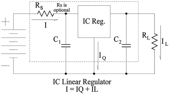
Figure 5
The design is very simple. The IC is connected in series with the power line and to the ground reference. In some cases where a different output voltage is needed, a resistor network can be connected between the IC’s output, ground, and the reference (bottom) terminal on the IC. The values of the capacitors are given on the data sheet. In the case of a battery supply, C1 can generally be omitted and a good value for C2 is often 0.1uF. Rs is an optional, series resistor that can be sized to drop part of the battery voltage when the load voltage is a lot smaller than the battery voltage. This decreases the amount of power that must be dissipated in the IC and therefore increases reliability. Again, calculations of the worst case power dissipation in both the IC and the optional Rs is needed.
If Rs = 0, then Pic = I x (Vb-VL). This calculated power must be less than the rated value of the IC package. Keep in mind that different IC packages may/will have different power ratings. Adding Rs is one way of keeping the power dissipated in the IC within this limit. If Rs is used (not zero Ohms) then the power calculations get more complicated. The value of Rs will be chosen for the maximum current situation and that will be where it’s power dissipation will be the most. Pic should also be at a maximum at that maximum current point, but I would check it at the minimum current and also around the half way point, just to be sure.
The efficiency of any linear IC regulator will be better than that of a zener regulator unless the zener is always operating with a maximum load current. When the load current decreases below it’s maximum value a zener will simply draw more current and keep the total power that is dissipated at a constant value. The IC regulator will draw a varying total current that changes as the output/load current changes. Therefore it is generally a lot more efficient.
As for life or dependability, IC regulators are generally as dependable as any other semiconductor based component. Since the current passes through them, they may be a bit more susceptible to surges than a Zener style regulator because transistors will fail faster than resistors. But if they are properly designed and installed with proper heat sinks, they can last for many decades. I would not hesitate to use an IC regulator in this application. If you want even higher efficiency, a switching regulator can probably provide that. Reliability may be somewhat lower, but not a lot.
Accuracy of IC regulators, both linear and switching, is generally excellent. They all use feedback techniques where the output is sampled to provide the correction signal to the series element which controls the output voltage. The degree of accuracy can vary with the internal circuit details, but numbers like 3%, down to 1% or even better are common. Again, as with the zener, the rated accuracy and the accuracy variation with circuit conditions are separate values so an IC regulator with a rated accuracy of 5% may be capable of holding the output value to within 1% or even better.
The LM317 that you mention is an adjustable regulator design. It requires that you use additional resistors to bias the reference pin for the output/load voltage you want. This can be an advantage if an odd voltage is needed but you can also get similar, three terminal regulators that have fixed output/load voltages and do not require those external resistors. Look at the 78xx series for positive regulators or the 79xx series for negative voltage ones.