How can I make a cable so that I could use a nine volt battery for my cell phone? Would a large six volt lantern battery work? Are there any electronics needed?
#6136
George Powelson
Ogden, UT
Please log in to post an answer.
Answers
How about 6V lantern battery?
First, a 9V "transistor" battery doesn't have enough current to run a cell phone. The Lantern battery might work. Look at your cell phone battery, it will be a Li-ion probably 3.7V, so you will need to lower the voltage of the lantern battery to that.
Next, measure or just read on the battery, which pins are + and -. Then, figure out how to connect to the small pins/strips inside the phone. In one of mine, I found that using the little hook-type clips worked fine.
That should do it. If you need to learn how to make a voltage reducing circuit, I believe that both linear types, using a LM317 chip as well as some of the newer switching chips have already been published in N&V. I found the LM2575. http://pdf.datasheetcatalog.com/datasheet/SemtechCorp/mXvqxtq.pdf
Philip Karras KE3FL
via email
First, determine how long you want the phone to run, and choose a battery with enough milliampere hours for the duration. (A 9 volt radio battery may be inadequate).
That said, for efficiency I recommend a switching converter such as the On Semi MC34063. See the datasheet for how to use. For an inexpensive inductor consider the toroidial inductor CR-345 from AllElectronics.com. This should have more than enough capacity to not run dry. If, in the future, you need a voltage inverter, be aware that I have found other datasheets to be in error with their circuit for this part, but the ON Semi circuit works well. Simply use the formulas in the datasheet. If the source voltage is close to 12 volts, than a surplus car adapter for your phone from Goodwill is the low cost option.
Jim Lacenski
Bellevue, WA
See question 7121.
I switched my tube system to separate units now using a Scott 350B. I need to check multipath distortion as in Tech Forum #7121, but wonder what bandwidth I need for a scope. I assume 100 MHz, but would a lower bandwidth (less costly) scope work okay? Would I hook it up as noted in #7121
#6137
Nick Oshana
Bristol, CT
Please log in to post an answer.
Answers
The oscilloscope only needs to be flat to 15kHz, so almost any one with at least 100kHz bandwidth will work. I did it with one of the 5MHz/5" scopes that were readily available since the 1950s (Dumont, Eico, Heathkit, KnightKit, RCA, etc.). You should be able to find a used one for less than $20. The connections are the same: FM detector to the X input and AGC to the Y input.
Joseph Feng
San Jose, CA
Since money for hobbies is hard to come by these days, is it worth trying to salvage parts from old electronic equipment to build new projects? What kind of equipment has the most usable parts — old TVs, computers, stereos? How far do component values deteriorate over time to become unreliable? Any advice out there?
#6135
Clint Stevens
Houston, TX
Please log in to post an answer.
Answers
I've been an electronics hobbyist since junior high school (I'm 57 now) and I've salvaged many components from PC boards and other electronic hardware for use in various projects. Sometimes the old stuff, in the many boxes of salvaged parts I have, has made it possible to complete a project. Don't forget to save hardware items also! I can't count how many times I've pulled out a bin of fastener hardware or brackets and found just what I need.
Another fantastic (and usually very inexpensive) resource for electronic and hardware parts is the surplus electronics market. In most larger cities there is at least one, and sometimes many, surplus electronics stores. I would say you have a very good chance of that in Houston. For example, anyone who lives in the SF bay area of California ("Silicon Valley") has a goldmine of surplus stores! One thing I usually do when visiting a larger city (if I'm driving, not flying - too expensive to transport) is to check the phone book for an Electronics - Surplus section and make some phone calls to get an idea of what's available.
If you decide to go ahead with salvaging parts from boards, you can begin inexpensively by using a soldering iron and a "solder sipper" (spring loaded vacuum device) and some solder wick to remove components. You will need to be careful not to heat individual component legs very long so as not to damage the components. It can be done. As you progress with this you can do some web searches for some less expensive desoldering equipment that will make it easier to remove components. You may even find some of this equipment at one of the surplus stores! Good luck!
Bob Chadwick
Lompoc, California
Absolutely! Since I was a kid, I've kept a stash of boards from dismantled equipment from which to salvage usable parts. While it started out of necessity, even now that I can afford to buy new parts for projects, it's still handy to have a selection of salvageable stuff on hand, and the best form of recycling is reuse.
If you are anything like me, sooner or later it will be 2am on a Saturday and you will find yourself needing a specific part you don't have and more often than not the junk box will save the day.
Most components hold up well with age. Semiconductors are almost always good, unless you are unlucky enough to find the part that resulted in the equipment being discarded in the first place. Reasonably modern components don't tend to drift much, although electrolytic capacitors may be suspect, particularly if they were used in a switchmode power supply.
James Sweet
via email
It is certainly worth salvaging parts from old electronics. My favorite tools for this are a desoldering iron (Parts Express model 372-202) and a Black & Decker heat gun (model HG1300). A good first device to take apart would be a VCR. Look for a heavy one made in the 80's or early 90's, it will have many basic parts like capacitors and inductors, along with more interesting bits such as a VFD display and a motor control chip.
In terms of what else to take apart: I would not recommend TVs, you can get a nasty shock from one, and the boards don't have much on them. Older computer boards have more through-hole chips than newer ones. (Heat gun works well here.) Stereos have a lot of good parts, from heavy duty transistors, to graphic equalizer chips.
I have not seen much deterioration of component values. Very old electrolytics sometimes can't hold a good charge. Most of the resistors in an old Vidicon camera I took apart were out of spec. In comparison, stuff from 20-30 years ago normally holds up very well. Capacitors with 'J' markings and resistors with gold bands almost always measure as expected.
Also, to dispel a couple of 'myths' about salvage that I frequently hear. “Don't bother removing LEDs or transistors, they always burn up.” This is not true, you can save anything if you work quickly enough. “Remember that salvaging costs money in electricity to run the iron/heat gun.” Not really, at 12 cents per KW/H, it costs about half a penny to use the 45 watt iron for an hour. If I use the heat gun, the cost per hour rises to a measly 16.5 cents.
Nicholas Amrich
via email
I have many old MiniDV or Hi-8 camcorders that still work very well as far as the camera and monitor, not so much for the recorder portion.
Has anyone thought of re-purposing these to just use the camera portion for a security/process monitor camera? Some old camcorders have superb resolution, a very low lux rating for color, and great remote control functions for focus, iris, and zoom. I would need to disable the time-out function for the recorder, which saves the heads if not running for a while by shutting down. Saves a lot over getting a PTZ camera — if you need the P & T, a small servo could do that function.
Anyone tried this? Please post your experience.
#6134
James Joyce
via email
Please log in to post an answer.
I want to build a 'drive by wire' system for a project that I have been working on. I have enough electronics knowledge that I feel I could build the circuit by hand if I could get help on the circuit diagram and parts needed.
I want to operate the throttle on a 14 HP engine via a servo with the gas pedal hooked to a potentiometer, so that when the 'gas' pedal is pushed, it will open the throttle on the engine and vice versa (close when 'gas' pedal is released). The servo would need to return to the same position as the pedal potentiometer.
The circuit needs to run on a 10-15 volt DC automotive voltage, and be turned on and off with the ignition switch. This would have to be bullet proof because of the vibration caused by the engine and terrain. The servo must be able to hold the throttle position for as long as the driver has his foot on the gas pedal in any position, and then return to the zero position when the foot pedal is released (return to the zero position). Can someone help me accomplish this?
#6133
Victor Dunford
via email
Please log in to post an answer.
Answers
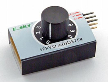
I think the simplest way would be to buy this servo adjuster (about $20), remove the pot and add your own wiring to your throttle control pot. With a low cost RC servo connected to the carburetor you should be good to go. Just do a search on the internet to find sources (even Ebay).
These RC servos are for 5V only, so you need to convert any 12 volts to 5V before using them.
Of course another way is to use a microcomputer like the Picaxe. This puppy has analog inputs (for the pot) and servo output. With a microcomputer you could add your own software to do other things, like keep the rpm constant with load changes. Again, it would be 5 volts only.
Also keep in mind a failure of the system may leave you without throttle control. Since you didn't state what this is for, be safe.
Any further questions or help you may contact me directly at: [email protected]
Paul Haug
via email
A stepper motor should work and there are already stepper motors being used in cars under the hood. You will need:
- An encoder to measure the position of the gas pedal
- A device to convert this position into pulses
- Another device to use the pulses to power a stepper motor
- And of course, the stepper motor itself
Digi-Key sells an encoder with 16 different pulse counts per revolution, set with tiny switches, for 26 bucks, part number AMT103-V. US Digital sells a chip that will convert the encoder output into pulses that a stepper driver can use. Part # LFLS7184, $3.50. Interinar sells a stepper driver board for $36.00. Stepper motors are available surplus everywhere.
You will have to have an idea which stepper you need if you decide to go this route. You will also need a 5 volt power supply for the encoder and the 7184 chip. US Digital also sells encoders but none that have 16 different resolutions, as far as I know. I have used all the devices mentioned, bought from the companies mentioned. I have used them for a similar application, so I know they will work. The encoder mentioned is a robust device that will be better over time than a cheap pot to measure the foot pedal position. Since the encoder has so many different resolutions it should be fairly easy to find a ratio between the foot pedal position and the throttle opening.
You could also use an RC servo to open the throttle. These servos need a pulse train of a particular width to know how much to move. The pulses must be constant, because when the pulse train stops the servo returns to the starting position. So, you need some kind of servo controller that will use a pot connected to the foot pedal to tell it how wide to make the pulse it sends to the servo.
The stepper solution suggested above, pretty much just requires connecting the different parts with wires according to the info in the data sheets. But, you can make your own servo controller from a 555 timer, some fixed resistors, some variable resistors (AKA pots), and some capacitors. You will need to solder all this together in an enclosure. This link: pcbheaven.com/wikipages/How_RC_Servos_Works/ will explain how RC servos work and has a sample circuit that you can build to control the RC servo.
One advantage of the RC servo is that it is an absolute positioning system. A certain resistance measured at the foot pedal results in a certain throttle position. The stepper system described above does NOT work that way. The throttle must be at the zero position when power is removed. If the throttle is at half way when power is removed, then the pedal will start to move the throttle from the half way position when power is restored, unless some type of mechanism always returns the throttle to the fully closed position, when power is removed.
Eric Snow
via email
I have a 40 year old Chevy. The fuel gauge bounces half the gauge reading when it gets under a 3/4 tank. I put in a new sending unit but that did not help. I tried a digital gauge and that helped some, but not enough. It is a 90 ohm sending unit, zero ohms (grounded) = empty and 90 ohms = full. I would like to find a circuit that will filter out the high and low spikes, and put out an average voltage reading based on the sending unit’s position.
#7131
Philip Diedeman
Phoenix, MD
Please log in to post an answer.
Answers
One of the suggestions was one that I was first tempted to suggest, but did not as it is potentially dangerous. The use of a filtering capacitor to dampen the voltage should not be tried. The sender circuit is low impedance and needs a very large value capacitor to be successful. Unfortunately that capacitor will store quite a bit of energy and the sender rheostat, in the presence of fuel and air, could create a spark that is sufficient to explosively ignite the fuel vapor. (Think TWA-800).
You have gotten a lot of good suggestions. The best ones deal with repairing the system as it was designed. You might want to make sure the sender is grounded properly and try an external wire back to the gauge to bypass the original one as a test.
Joe Leikhim
Oviedo, FL
The type of filter you need is called a "median" filter. I designed it in software when I worked for Marsh-McBirney, Inc developing flow meters. The data you have can be filtered with a PIC to keep anything from three to seven readings & then just select the value in the middle of the pack. Use even higher numbers if the readings aren't stable enough. With our units taking five readings, it did the trick and was immensely better than an "averaging" filter which took forever to ramp up or shut down, not to mention you never saw anything close to a real time value.
Philip Karras KE3FL
Mt Airy, MD
Most of the older vehicles used a +5.0 VDC voltage for all of the instrument cluster. And, the sending unit in the gas tank is one of the resistors in the Wheatstone Bridge circuit for the gauge. In my 1977 GMC 1/2 ton pickup I had the exact same problem. I fixed it by removing the dash group and then removing the gas gauge. The gauge had two long screws with loose nuts that depressed into some clips that connected to the flimsy circuit traces. I carefully tightened those nuts. I still had the typical GM problem of driving for a week to work, and at 1/2 tank I could only make it to work one more day, because the gas needle went to empty in 30 miles. I'd suggest checking your gas gauge connections in the cluster, loose nuts on the gauge's protruding screws, and the flimsy circuit trace connections.
Larry Kraemer
Jackson, MO
On my old Dodge, (and this applies to Fords and Chevys too) the instrument panel has a thermal voltage regulator. The instruments operate at a voltage of about 5-7 volts. The guages have built in damping.
The thermal voltage regulator is nothing more than a bi-medal strip with a heating coil on it, that opens and closes a contact, thus maintaining a poor, but semi constant voltage. I've replaced these devices with simple voltage regulators like a LM317, set to a voltage that approximates 6 volts. More reading here. www.chevytrucks.org/tech/gasgauge.htm
Mentioned in the above link, is to check for a GOOD ground at the sender in the tank.
Nirodac
Vancouver BC
I saw the removal of a gas tank and the sending unit was a variable resistor. This resistor sits in the gas! I would not play with this system period!
George F. Powelson
Ogden, UT
As you know, a gas sending unit is just a variable resistor acting as a voltage divider. There are several possible reasons for a jumpy reading. One would be if the float is not well placed in the tank and the gas sloshing around just moves it up and down. If that is the case, a filter may help.
Since the gas level should change very slowly, a simple series connected capacitor/resistor combination connected from the output of the sending unit to ground would be a good filter. A large electrolytic with a high enough Voltage rating to withstand any spikes in the 12V system would be best.
You need a time constant that is longer than the period of the gauge's jumps; perhaps a couple of seconds. But you also need a resistance that is small enough to allow enough current to pass through it when needed to maintain the dial reading. TC(Time Constant) = R * C or C = TC/R. R is the value of the series resistor. I would take it to be a few Ohms, perhaps 10 as a first try.
It is a bit hard to calculate the power dissipated in this resistor as it depends on the frequency and severity of the fluctuations but I would start with at least a 1 Watt size and if that burns up, try 5 Watts. With a one second time constant we have: C = 1/10 = 0.1 Farads That is 100,000 uF which is probably impractical. I would try a nice large electrolytic and see what happens. 20,000 uF at 25 Volts would be a good first choice.
If that helps but is not enough, go larger. The negative (-) terminal on the capacitor would go to ground. It does not matter which side of the capacitor the resistor is on as long as it is in series with it. This will not effect the accuracy of the readings as long as the added resistor is not in series with the line to the gauge.
Another possible cause would be a bad sending unit, but you say you have already replaced it so that is not likely. A third cause would be bad wiring between the sending unit and the gauge. Before you try anything else, you might run an extra, temporary wire to see if it helps. If it does, repair the harness.
Finally, it could be a bad gauge. After trying the above filter and extra wire fixes, you could temporarily rig a 100 Ohm pot at the dashboard to activate the meter. Disconnect the wire from the sending unit and observe the meter as you drive down a bumpy street. If it still jumps, it is the gauge itself and that must be replaced.
Paul Alciatore
Beaumont, TX
How do you make a ham radio antenna shorter with a coil? For a dipole or yaggi.
#5135
George Powelson
Ogden, UT
Please log in to post an answer.
Answers
I have two slinkys that I've used as a dipole for 20-80 meters, with a tuner. If you make a coil with the wires close together, you have an inductor. So the larger you make the loops and the further apart the loops are from each other, the lower the inductance will be. That said, I don't think you'll really want to do that with regular copper wire. It might work with copper coated steel wire, but I've never used it, so I don't know. On the other hand, a slinky is not made of copper, it is probably some kind of steel. You can buy the original slinky on-line or at a Cracker Barrel restaurant, that's where I got my two originally.
If you do try to build your own, then try using the length you want for the longest wavelength you want to transmit on and add some extra. Then make a coil with large loops, 3" diameter or larger, and space them apart about an inch or so. If you do not want to use a tuner then you'll probably have to add some capacitance to it at the center of the dipole and this value will change depending on the transmitting frequency. Or, perhaps cutting wire off to make it shorter will be all you need to do. Buying a tuner makes using strange things as antennas much easier.
I hope that helps.
Phil Karras, KE3FL
Mount Airy, MD
Can someone make an experimental circuit that uses a motion detector? I want to feed the signal to a microcontroller for logging movement or object identification.
#5134
George Powelson
Ogden, UT
Please log in to post an answer.
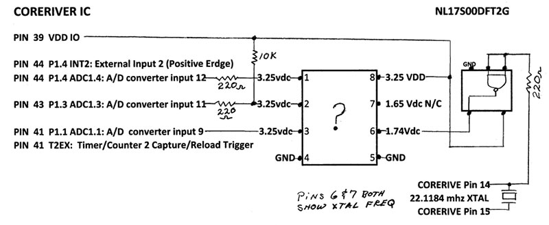
Figure 1 is a schematic I drew of the IC in question. I have not been able to find any IC that would connect in this circuit. There is only a date code on it. Nothing else at all. Pin 6 is obvious, but with pin 5 to ground and pin 7 not connected, I am stumped. The only IC I thought it could be is a serial Flash memory. Any other suggestions?
#5133
Daniel Zielinski
Port Saint Lucie, FL
Please log in to post an answer.
Answers
What about the good old 555 timer IC?
Camillus Blockx
KNOX
I built a Jeopardy game console for use in a classroom setting. The console works quite well and can accommodate up to four players or teams. The issue I have is that the player buttons are attached to the console via cables and this gets cumbersome in class. I'd like to find a wireless solution where the push of a button would wirelessly close an associated relay in the console. I've looked at commercial solutions and they are all north of $200. Can anyone suggest a circuit that I could use that would be relatively inexpensive and easy to build? I would be willing to consider a commercial solution but, as I said, all the ones I've found so far are out of my price range.
#5132
Pete Schestopol
Atlanta, GA
Please log in to post an answer.
Answers
A solution that worked for me several years ago was to use a wireless doorbell. These generally have a jumper that you can move to avoid interfering with a neighbor that has the same model. You would have to purchase four units and then set each to a different "channel". If your console is not made of metal, you could mount the base units inside the console. Disconnect the speakers if you do not want them to chime. A quick check on Google shows these are available in the $10 to $15 price range. The Honeywell RCWL105A is one that might work for you.
There are both 120VAC and battery operated base units. The push buttons are battery operated in either case. The advantage of the 120 VAC units is that you do not have to purchase batteries and also remember to remove them when not in use. The disadvantage is it may be more difficult to interface these to your console.
I used an AC powered base and added a small 5V relay to provide a contact closure to operate my garage door opener. Note that this will be a momentary contact closure. I could not find a schematic for the unit I used but was able to use an oscilloscope to find a pin that changed state when I pushed the button. The relay takes too much current to be driven directly so I added a FET to act as a low side driver. An optical isolator might also work instead of the relay. These can be driven with only a few mA if the output transistor only has to sink a few mA. BE VERY CAREFUL and don't even attempt to connect an oscilloscope to an AC powered unit unless you have an isolation transformer since these units may operate directly from the 120VAC with no isolation. The relay or optical isolator will provide the isolation once you have found a place to connect it. You can contact me via email at [email protected] if you have questions.
Mark E. Whitmore
Frederick, MD
For wireless control, it is tough to beat the low cost of Sony TV remotes from the local Goodwill, teamed with the IR-D15A 15-Bit Sony® IR Decoder IC from Reynolds Electronics. For RF remote control, there are multiple articles on how to use PIC or Atmel (Arduino) processors using serial communication, simply search or stop by the Microchip site.
An alternate encode/decode is the TX-2/RX-2 "RC car" remote control IC sets available from eBay. Recommend the TX-3/RX-3, and buy in pairs. If using RF instead of infrared, consider the WRL-10535 and WRL-10533 transmitter/receivers from www.sparkfun.com, which I personally use with the TX-2/RX-2 "RC car" set for fan control. The TX-2 can connect directly to an RX-2 for debugging, and it is easy to scope the output. A PIC (16F88) or ATmega32x (Arduino) will probably help for "who clicked first". Holtek also produces inexpensive encoder/decoder pairs. www.allelectronics.com has Sharp IR decoders which work fine with the Sony remotes, AVRs, and much more.
Jim Lacenski
Bellevue, WA