PICAXE products offer an attractive alternative to novices who lack experience using microprocessors and would like to learn more about them without a major investment in development tools and software training. PICAXE chips are Flash-programmed PIC processors containing a proprietary interpreter that offers powerful, easy-to-use, BASIC-like instructions. The chips are inexpensive, and the editing software for writing and testing the program is a free download. Ample info and tips are available in forums and published manuals. What else could you want?
Many hobbyists are reluctant to venture into new technology because of startup costs. A PICAXE provides a low cost way to get started with microprocessors. There is one catch, though. You may have assembled your first circuit on a solderless breadboard using only a few dollars in parts and written and debugged a program with the fun and exciting simulator built in to the free programming editor, only to discover that transferring the program from your PC into the PICAXE chip required a special USB download cable. This article addresses that issue.
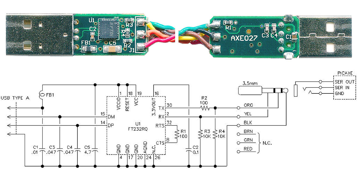
The PICAXE system uses a serial comm cable to send a program from the program editor in a PC directly into the chip. No other programming equipment is required. PICAXE's AXE027 download cable has a USB-to-TTL RS-232 converter circuit on a small printed circuit board (PCB), which is embedded within a molded USB Type A connector at one end and a 3.5 mm miniature stereo plug at the other end. The PCB is a bit of an overkill, with top, bottom, and intermediate ground plane layers.
Figure 1 shows details of the PCB assembly removed from a recently acquired AXE027 cable and its schematic.
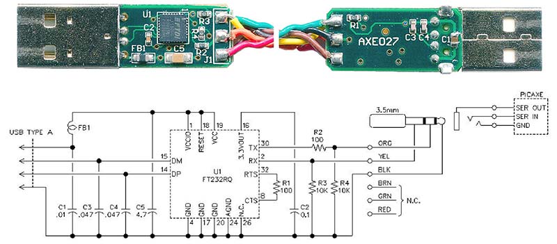
FIGURE 1. AXE027 PICAXE download cable.
This assembly is similar to an older design shown in PICAXE documents, but it has a few minor differences.
The cable uses an FT232Rx series converter — a chip found in many USB-to-serial converters because of its versatility, as well as the availability of drivers for a wide variety of operating systems. One reason PICAXE chose this chip was because of its compatibility with the company's original serial comm system. FTDI's converter chips allow you to invert the TX and RX signals so they are active low, just like standard RS-232 signals.
When you look at the chip's configuration EEPROM with FTDI's utility program (FTProg 2.6.8), the descriptive data for the AXE027 is:
Chip Type: 'FT232R'
Vendor ID: 0403
Product ID: BD90
Product Description: 'AXE027 PICAXE USB'
Under hardware-specific invert RS-232 signals, FTProg shows that TXD, RXD, RTS#, and CTS# were all inverted. (Output designations are followed by a # symbol if they are active low by default.) Note that RTS and CTS are jumpered together through R1 on the board. Inverting TXD and RXD is absolutely necessary, but other cables I have tested seem to work just fine with or without inversion of RTS# and CTS# — regardless of whether they are connected. Also, some PICAXE documentation shows a 100 ohm resistor in series with RX — like R2 in series with TX — but my purchased sample has no such resistor nor any place for it.
FTProg also shows that all five CBUS outputs of the AXE027 cable were reconfigured from their FTDI factory default configurations to TXDEN. I don't know why that was done, but it has nothing to do with using the cable to download PICAXE programs. In summary, there are ways that PICAXE could have made it difficult to substitute third-party download cables, but to their credit there is no evidence they have attempted to do that.
The requirements for a USB download cable for PICAXE are few and simple: just three wires — serial in, serial out, and ground. The key component is a USB-to-RS-232 converter chip that can operate at 5 VDC and 4800 baud (the PICAXE comm frequency). There are at least four major suppliers of these chips worldwide: FTDI, Prolific, SI Labs, and Microchip; some can provide the inverted RX/TX configuration. For the others, you can add a couple of simple inverters. Purchasing a ready-made converter module or breakout board can save you the tedious job of soldering the small closely-spaced pins of a converter chip.
Figure 2 shows a basic download cable circuit using a module with an FTDI 232 series or Microchip MCP2200 chip, either of which allows you to invert the RX/TX signals by modifying the internal configuration of the EEPROM.
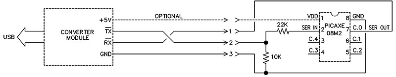
FIGURE 2. Download cable using a converter module that can provide inverted RX and TX.
I've shown a generic three-pin connector rather than the stereo connector used by PICAXE. The 22K and 10K resistors cannot be part of the cable. They keep the PICAXE serial input from floating around like an antenna when the download cable is disconnected, which could result in noise pickup that might interfere with program execution. Their importance is clearly explained in PICAXE documentation.
If you want your download cable to be really small, take a look at Jim Paris' FTXUSB serial breakout board (www.tindie.com/products/jimparis/microftx-usb-serial-breakout-1/?pt=directsearch). At only 0.4" x 0.64" — including a micro USB B connector — it's the smallest cable currently being made. It uses a tiny FT230XQ chip with RX and TX signals that you can invert with FTProg. The cost is a little over $12 shipped, to which you must add a USB micro cable and an output cable.
The next largest category is the CRIUS FTDI basic breakout board. This high quality FTDI board also doesn't need extra inverters. All you would need to do would be to install input and output cables and use FTProg to invert RX and TX.
Omega MCU Systems sells a board with an SI Labs CP2103 chip and a couple of transistor inverters added (www.onebytecpu.com/usermanuals/u2p_datasheet.pdf), but you would still need cables. It's also a little clunky.
You can buy a postage stamp-sized MCP2200 breakout board direct from the manufacturer (Microchip) or from major electronics suppliers (Digi-Key, Mouser, Newark, Farnell, etc.). Microchip provides an EEPROM configuration utility that is similar to FTProg that allows you to invert the RX and TX signals. All you would need to add would be cables.
For the lowest cost download cable, you can use a USB-to-TTL converter module based on a Prolific PL-2303HX chip or an SI Labs CP-2102 or 2103 chip. These are available from many sources in China, Taiwan, and Hong Kong. Figure 3 shows some examples.
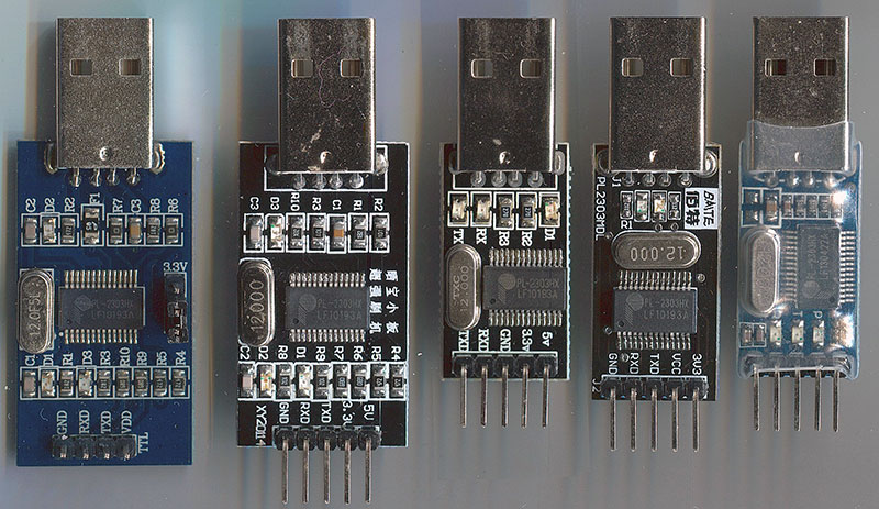
FIGURE 3. Examples of Prolific and SI Labs USB modules.
An easy way to recognize a board using a Prolific or SI Labs chip is the 12 MHz crystal. (FTDI-based boards use a built-in oscillator, so no external crystal is needed. The MCP2200 board uses a tiny 12 MHz ceramic resonator.) Most modules have five output pins (RX, TX, GND, +3.3V, and +5V), giving you a choice for powering other circuits. Some boards (like the one on the left) only have four pins, with a jumper block for selecting Vdd (+3.3V or +5V).
There is no standard pinout sequence. You can temporarily power your PICAXE circuit from the module, but for a final design use something that works when the download cable is unplugged.
Nearly all modules have one or more LEDs to indicate power, transmit, receive, etc. All of them use a USB Type A connector which eliminates the need for a separate USB cable. My favorite is the board at the far right of Figure 3, which is supplied with a protective outer wrapper of clear heat shrink tubing. It uses a Prolific PL-2303HX chip, is well built, reliable, and has good stable drivers.
If you search Google for CEG004200 or search eBay for PL-2303HX, you'll find it widely available. None of these boards have the capability of inverting RX and TX. You must add a couple of inverters powered by the module's +5V output. That's easily done in several ways.
Figure 4 shows how you can use discrete transistors and resistors for the inverters.
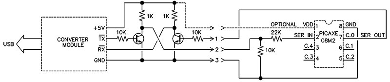
FIGURE 4. Download cable with transistor inverters.
Any type of NPN transistors can be used, and the resistor values are not critical. Note that the 22K and 10K resistors from Figure 2 are still necessary to prevent noise on the serial input when the cable is disconnected.
Transistor inverters are inexpensive and parts are readily available. However, if you want to simplify your cable with just one component instead of six, you can use almost any digital IC with two or more inverters, such as the 74HCT04 hex inverter or the 74HCT00 quad NAND shown in Figure 5.
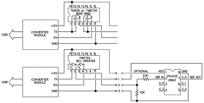
FIGURE 5. Download cable with DIP IC inverters.
There are many choices of similar ICs in a 14-pin DIP package with through-hole leads, and many hobbyists prefer this type of package because it is easy to work with when using perfboard or a solderless breadboard.
If you can deal with surface-mount components and want something elegant, a good choice is the SN74LVC2GU04DBVR in a tiny SOT-23 package with just six pins as shown in Figure 6.
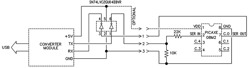
FIGURE 6. Download cable with SMD dual inverter.
To package the additional inverter circuitry, attach a small perfboard extension to the end of the module board with epoxy. For connections to the inverters, use tiny #30 gauge wire-wrap wire or strands from stranded hookup wire. After anchoring a three-conductor cable and testing the unit, cover the add-on board assembly with epoxy or heat shrink. To test your completed cable — including the inverters — jumper pin 1 to pin 2, and then use Windows HyperTerminal (or any other serial comm utility software) to perform a loopback test.
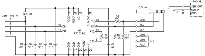
FIGURE 7. AXE027 schematic.
If you are using a PICAXE development board, you can terminate the cable with a standard 3.5 mm stereo plug or any suitable three-conductor connector. Since most of the converter modules will operate up to 115 Kb, you can use your cable for many computer interface projects other than PICAXE downloading. Most other applications for a serial comm cable use standard TTL polarity signals, so you won't need the inverters. NV
PARTS LIST
Here’s a summary parts list that applies to the simplest versions of the cable. Select the miscellaneous parts per the version you are building.
| Prolific PL-2303-HX Converter Module |
| 2N3904 NPN Transistor |
Digi-Key Part Number 2N3904FS-ND |
| 1/8W Resistor 1K |
Digi-Key Part Number CF18JT1K00TR-ND |
| 1/8W Resistor 10K |
Digi-Key Part Number CF18JT10K0CT-ND |
| 74HCT04 Hex Inverter |
Digi-Key Part Number 296-1605-5-ND |
| 74HCT00 Quad NAND |
Digi-Key Part Number 296-1603-5-ND |
| SN74LVC2GU04DBVR Dual Inverter |
Digi-Key Part Number 296-13276-1-N |