As hard as it might be to believe, I have never built an electronic clock of any kind. I've always thought electronic clocks were passe and not worth the time to design and build one.
In addition, I thought that all the really interesting electronic clock designs had already been built, so why bother. However, as I was looking around for something to do with the 15 feet of RGB LED ribbon I purchased from Adafruit.com, it occurred to me that I could use a short segment of the ribbon (14 LEDs’ worth) to build a unique electronic clock which used the RGB LEDs to display the time and date, function as a mood light, and also run some animated bright and colorful patterns. I also decided to control the clock with an IR remote control so no physical access to the clock would be needed. Maybe designing and building an electronic clock could still be cool after all.
I already had an Arduino Uno microcontroller, an IR detector/sensor, and an IR remote control available, so the only part I was lacking was a real time clock (RTC). I decided to use a battery backed-up RTC to make the clock accurate, reliable, and impervious to power failures. I chose the ChronoDot ultra precise RTC module spec'ed at less than a minute of drift per year.
Designing the LED clock circuitry was easy because of the small number of parts involved. To simplify the design, I decided to power the clock via USB so no power supply components (internal to the clock) would be required. With all of the parts in hand, I breadboarded the circuitry and wrote the software for this unique LED clock using the Arduino 1.0.5 IDE (Integrated Development Environment) on my MacBook Pro.
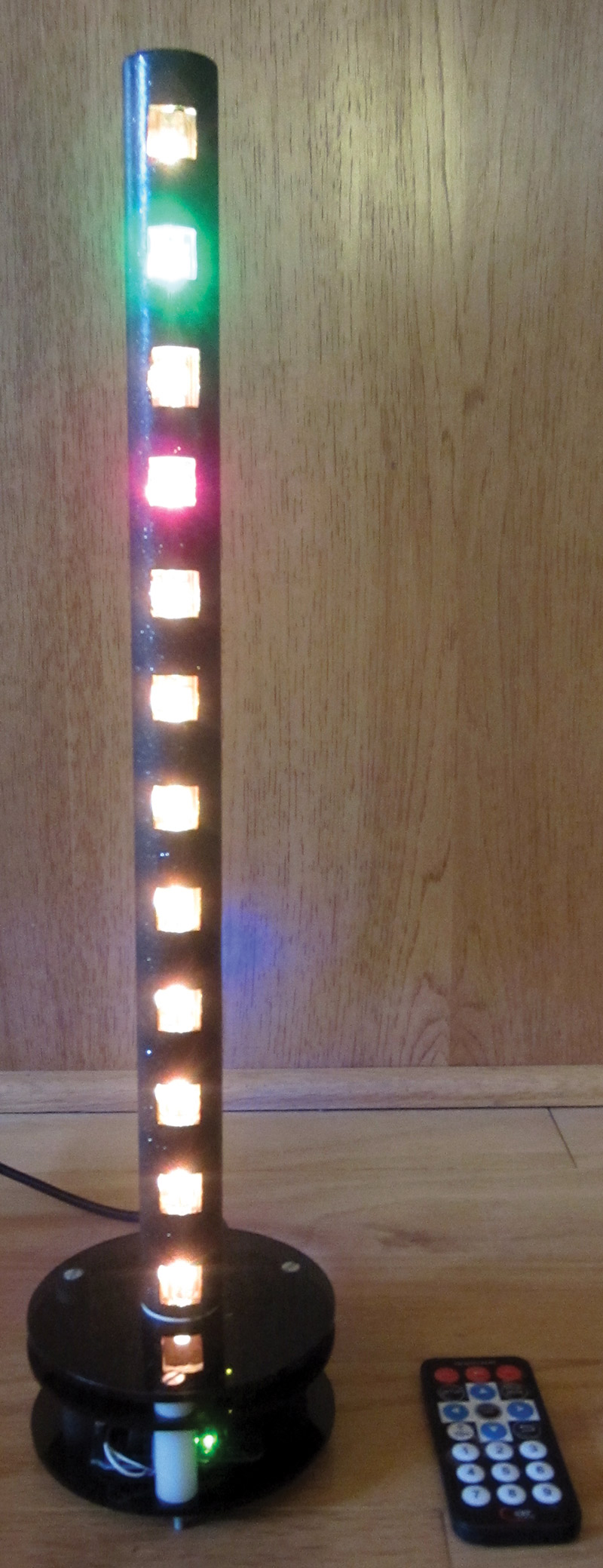
PHOTO 1. LED clock in operation. As you can see, the LEDs are very bright! The time shown is between 9:55 and 9:59.
The Clock Hardware
As mentioned, the hardware for this unique LED clock is quite simple and is shown in Figure 1.
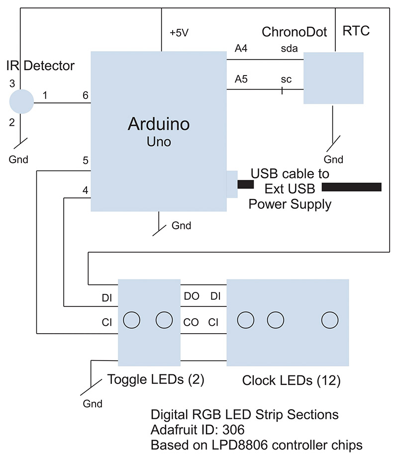
FIGURE 1. Schematic diagram.
The clock is powered by an external USB power supply connected via a USB cable plugged into the Arduino Uno’s USB connector. All of the clock’s components run on the five volts provided by the Arduino Uno board.
The IR detector/sensor’s output is connected to pin 6 of the Arduino which is configured as a digital input in software. The two Arduino digital outputs on pins 4 and 5 drive the RGB LED strip via some bit-banging performed in the software.
Finally, the ChronoDot RTC assembly is connected to the Arduino’s I2C/TWI interface via pins A4 (SDA) and A5 (SCL). NOTE: If you use a different Arduino model for this clock, the pins for the I2C/TWI interface will almost certainly be different and must be taken into consideration.
All of the components are wired directly to the Uno board via inline connectors; no shield is involved, though you could use a prototyping shield if you like. Once you have the hardware wired up, insert the RTC battery into the socket. According to the specification, this battery should keep the RTC running for at least seven years.
That’s about it for the hardware. As you may now realize, most of the clock’s functionality is provided by the software.
The Clock Software
The software consists of two files: datatypes.h and AUniqueLEDClock.ino. Both are available at the article link. These files must be moved into a directory called AUniqueLEDClock you create in the Arduino development area on your computer.
Two Arduino libraries are needed by the clock. The wire library for I2C/TWI communication and the IRremote library for remote control operation. The wire library is part of the standard Arduino IDE and doesn’t require installation. The IRremote library, however, must be installed before being used. See the Resources for info on how to get the library and install it. Code to control the ChronoDot RTC and the RGB LED strips is embedded in the ino (or sketch) file.
Once you have the clock files and have installed the IRremote library, you should be able to bring up the Arduino IDE and load the code. Make sure you select the Arduino Uno board type from the Tools menu or you will have issues. If you click the Verify button and don’t see any errors, you should be able to click the Upload button to program your Arduino.
If all is well, the clock should go into the clock display mode (more on this in a bit) and you should be good to go.
The best way to understand the code is to examine the sketch file in detail. There isn’t enough space in this article to give a detailed description of how the code works, but I will give you a quick rundown.
All Arduino sketches have two entry points: setup() and loop(). In our setup() function, all Arduino I/O pins are configured for interacting with the external hardware, the random number generator is seeded, the wire library is initialized, and the IRremote library is enabled for reception of IR signals. A check is then made to be sure the RTC is running, then the Arduino’s EEPROM is initialized for storage of the clock’s color configuration information. Finally, all of the RGB LEDs are turned off until needed.
The loop() function is a lot more complex. In essence, it runs a series of state machines that control the operation of the clock. I chose a state machine implementation because it makes the code easier to read and maintain than if it were coded with massively nested if-then-else structures.
In a state machine, transitions between states occur when specific stimulus is applied while in a current state that is expecting it. All extraneous inputs are ignored. The input stimulus (in our case) results from keys being pressed on the remote control.
A good example of state machine operation can be seen in the function hsvColorSetter in the sketch. Here, clicking keys on the remote control causes the state machine to move back and forth between two states while the user configures a color for use in the clock. Clicking the STOP/MODE or the ENTER/SAVE keys on the remote causes the state machine to exit with the definition of the HSV color the user was setting.
HSV (or Hue, Saturation, and Value) color values are used extensively in the clock’s code. Each of these color attributes can be manipulated independently and have different effects. Hue is the actual color of the color and is specified in degrees between 0 and 359. A hue of zero is red, a hue of 120 degrees is green, and a hue of 240 is blue. Hues in between these values are a mix of the surrounding colors.
Saturation determines how pure a color is and has values between 0.0 and 1.0. Fully saturated colors are deep and full, while lesser saturated colors trend towards pastels and white.
Value determines the brightness of the color and also ranges in value from 0.0 to 1.0. The higher the value, the brighter the color. As an example, a hue value of 0.0, a saturation value of 0.0, and a value of 1.0 results in the color white.
Inside the loop() function, the current time and date is read every second from the RTC and displayed on the LEDs if the clock is in clock mode. Other things happen in the other operational modes of the clock. See the discussion of the Remote Control for more info.
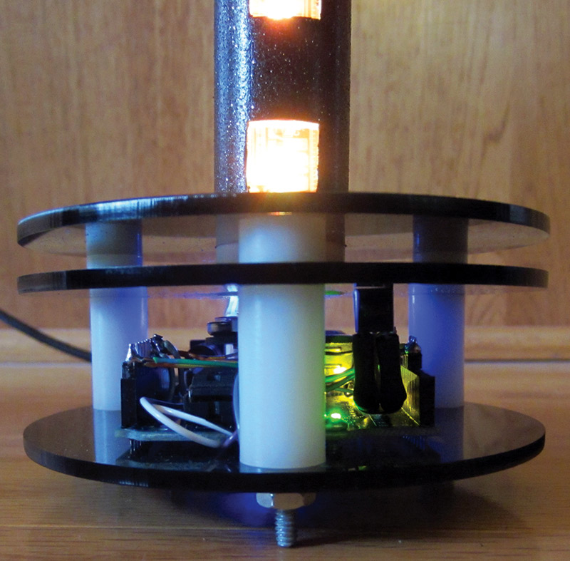
PHOTO 2. LED clock base detail. Base made from three 4" smokey colored acrylic discs, some spacers, and long screws. IR detector is positioned vertically on the right of the white spacer, facing forward.
Reading the Clock
Reading the Time
I packaged my clock in a rather unique vertical format, so it takes a little time to get comfortable reading it. While displaying the time, all of the LEDs are first set to the background color (default blue), then the hour value is displayed (default red) with the top LED indicating 12 o’clock and counting down towards 1 o’clock at the bottom.
Since minutes are displayed on the same scale, they are only available with five minute resolution. To determine the minutes count, count up by fives from the bottom LED. For example, if the fifth LED from the bottom is lit (minutes are displayed in green by default), the minute count is between 25 and 30.
How often do you need the exact minute count? Not often, so a five minute resolution was deemed sufficient. Since hours and minutes are displayed on the same group of LEDs, there is often (once per hour) a conflict on which color to use. In these cases, the LED in conflict will blink back and forth between the hour and minute color.
For example, if the time is 10:50, the 10th LED from the bottom will blink red then green until the minute value changes, at which time there will again be one red LED for the hour and one green LED for the minutes displayed.
While time is being displayed, the two LEDs I refer to as the toggle LEDs alternate between the toggle color and off. The idea behind these LEDs is to simulate ticking of the clock.
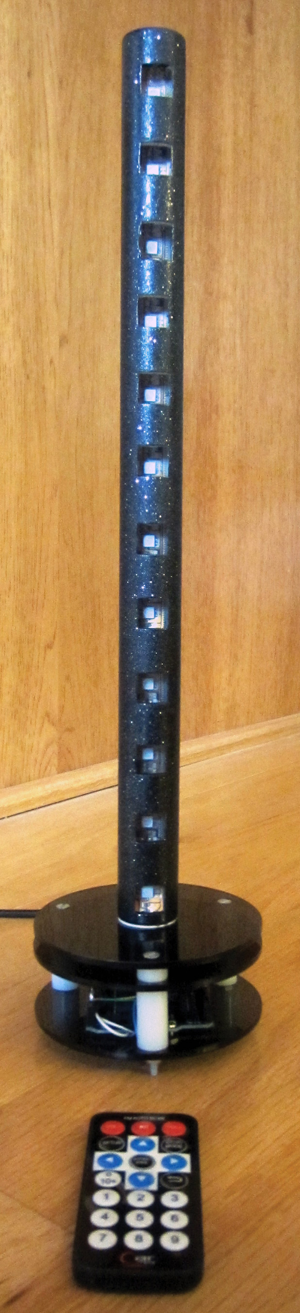
PHOTO 3. Here, you can see the RGB LEDs through square holes cut into the 1" PVC pipe. The PVC pipe was press-fit into a 1" hole drilled through the top two acrylic discs and painted with a dark gray sparkle paint.
Clock Events
If the clock did nothing but display time, it would get boring pretty quickly. To prevent boredom, I defined three events which fire periodically to liven things up. There is a 10 minute, a 15 minute, and a 30 minute event. With each 10 minute event, the time display is suspended and a beautiful rotating color wheel or rainbow effect is displayed.
With each 15 minute event, the clock goes from completely dark to brilliance blue in slowly increasing steps. With each 30 minute event, the full date is displayed. You have to see these events to appreciate them. The clock returns to its normal time display as soon as the event display is completed.
Reading the Date
The date will be displayed in a month/day/year sequence with unique colors for each quantity. Month (with a value of 1..12) maps directly to the LED display with January (or month one) at the bottom and December (or month 12) at the top. The day of the month (values 1..31) will be indicated by a rising dot in the day color, starting from the bottom LED and wrapping around the display as many times as necessary.
For example, the 29th of the month will loop through all of the LEDs twice (for a 24 count) and then light the fifth LED from the bottom to indicate the 29th. When displaying the year, the bottom LED indicates 2010 with each subsequent year one LED higher.
Remote Control
All aspects of the clock’s operation are controlled via a 21 key IR remote control; there are no other buttons or switches to manipulate.
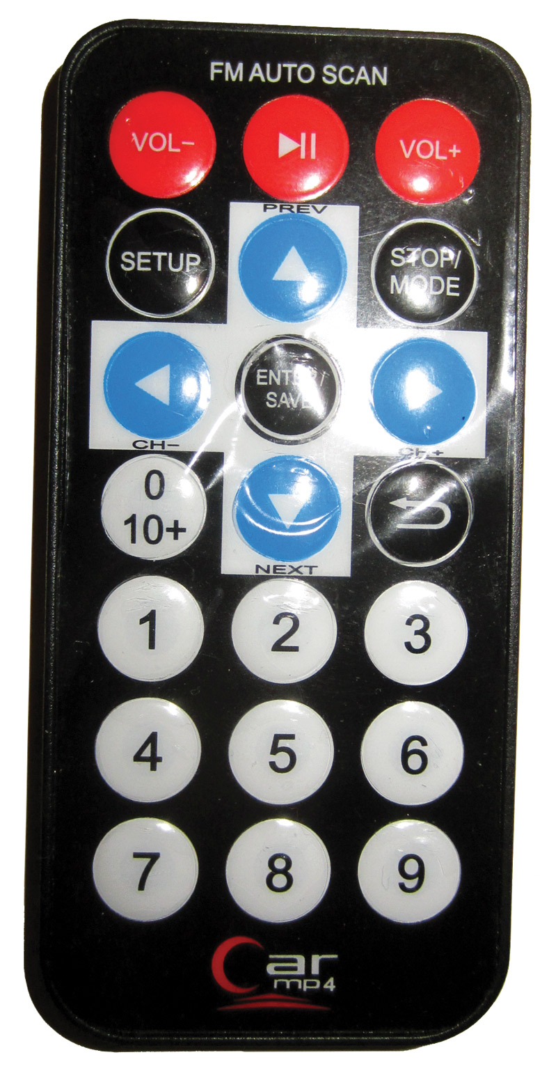
PHOTO 4. The IR remote control.
The software I wrote for the clock embodies how I thought the remote control should work. You can change things if you so desire since you’ll have access to the source code in the Arduino sketch which can be found in the downloads.
When the clock is first powered up, it immediately goes into clock mode even though the time or date has not yet been set. All colors used for display will be set to defaults coded into the software.
NOTE: The clock will retain the colors you configure for each mode (even if the clock loses power) and will use these colors until changed again.
The clock will remain in clock mode until interrupted. Hitting the STOP/MODE key (the interrupt key) on the remote causes the clock mode to be exited and all LEDs to flash white indicating an interrupt has occurred and that you have the clock’s attention. The clock now awaits your command input via the remote control. Here’s a description of each key:
1 Key — Clicking this key causes the clock to go into clock mode. The clock will stay in clock mode displaying the time and date until interrupted.
2 Key — Clicking this key causes the clock to go into mood light mode where all of the LEDs display a mood light color of your choosing. Mood light color is altered using the 1 and 7 keys to change the color’s hue up and down, respectively; the color’s saturation is adjusted using the 2 and 8 keys; and the color’s value or brightness is changed using the 3 and 9 keys.
The clock will remain in mood light mode until either the ENTER/SAVE or the STOP/MODE key is clicked. At that time, the clock will go back into interrupt mode awaiting a further command.
3 Key — Clicking this key puts the clock into pattern display mode. Without further user input via the remote, the clock will randomly choose one of its built-in display patterns to show and the speed at which to display the pattern. If you wish to change the speed of the pattern’s animation, use the up and down arrow keys on the remote (up faster, down slower), followed by the ENTER/SAVE key to engage the new speed.
You can also select a different pattern for display by using the left and right arrow keys followed by the ENTER/SAVE key to select the new pattern. Clicking the STOP/MODE key interrupts the pattern display mode and moves the clock back into command mode.
4 Key — Click this key to set the clock’s time. You first set the hour, then the 10s of minutes value, and then the minute value. Valid hour values are 1..12. Use the up and down arrow keys on the remote to set the hour value.
When the hour is correct, click the ENTER/SAVE key to proceed to setting the 10s of minutes value within the range of 0..5. A zero 10s of minutes value is indicated by no LEDs being lit. You must click the up key to set a non-zero 10s of minutes count.
When satisfied, click the ENTER/SAVE key to set the minute value within the range of 0..9. Clicking ENTER/SAVE after you have set the minute value puts the clock back into clock mode, which should display the time you have just set.
5 Key — Click this key to set the date. Setting the date is similar to setting the time except the values to set in order are month (1..12), 10s of days (0..3), day (0..9), 10s of years (1..9,) and year (0..9). After you set the date a couple times, you’ll get the hang of it.
6 Key — Click this key to set the background color of the clock which is blue by default. Color is set as described for mood light mode.
7 Key — Click this key to set the colors associated with the time display. By default, the hour is displayed in red and minutes in green. You first set the hour color, then the minute color.
8 Key — Click this key to set the colors associated with the date display. By default, month is displayed in yellow, day in magenta, and year in cyan. You first set the month color, then the day color, then the year color.
9 Key — Click this key to set the color of the toggle LEDs. By default, the toggle LEDs display in red but you can change that to whatever color you desire.
SETUP Key — When you click this key, all of your configured colors — for all modes — are erased and the default colors are reinstated.
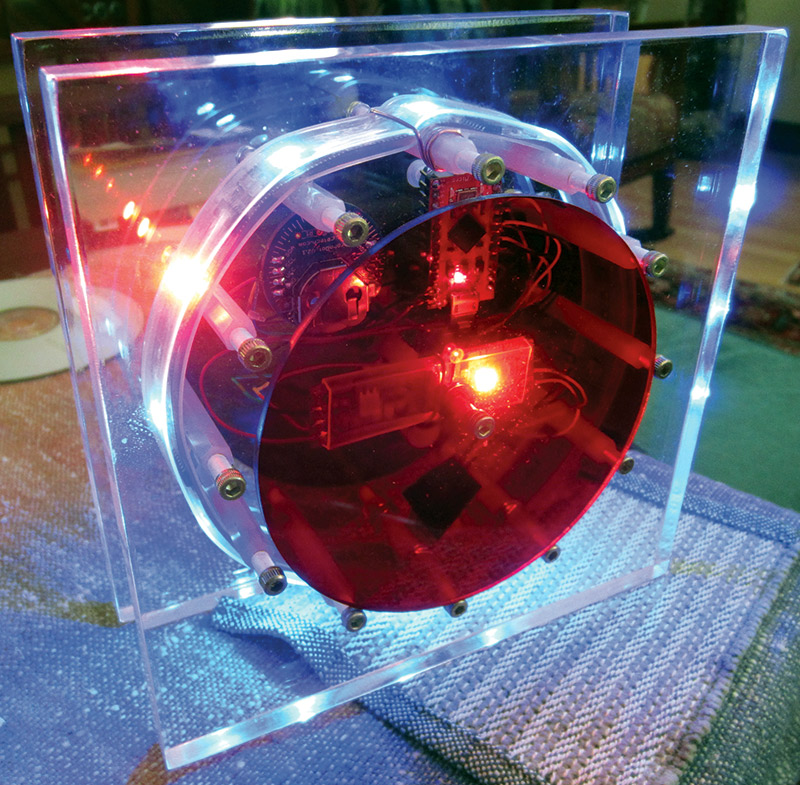
PHOTO 5. Alternative packaging using a SparkFun Pro micro Arduino.
Packaging the LED Clock
When I decided to build this clock, I wanted to make it unique looking as well as functional. In my first build, I made the clock out of acrylic discs and a vertical piece of PVC as shown in the photos. This resulted in a space-age/modern look which always takes people by surprise when I tell them it’s a clock. When I decided I wanted one of these clocks for my desk, I decided to package it more like a “normal” clock. This version can be seen in Photo 5.
You, of course, can package your clock anyway you like. NV
Parts List
| ITEM |
SUPPLIER |
COMMENTS |
| Arduino Uno microcontroller |
eBay, Adafruit, mcmelectronics.com, RadioShack, and many other places |
Other Arduinos could be used but the sketch would need to change |
| ChronoDot ultra precise RTC ID: 255 |
Adafruit |
Comes with battery |
| Digital RGB LED strip portion* ID: 306 |
Adafruit |
Two LEDs in length for the toggling LEDs |
| Digital RGB LED strip portion* ID: 306 |
Adafruit |
12 LEDs in length for the clock LEDs |
| IR detector/sensor |
RadioShack IR receiver #2760640 or Adafruit model TSOP38238 ID: 157 |
|
| 21-key IR remote control ID: 389 |
|
Other remotes could be used but Arduino sketch would need to change |
| USB power supply |
|
Must be capable of around one amp at five volts |
| USB to Arduino cable |
|
Sometimes provided with Arduino Uno purchase |
| NOTES: |
| *LED strip is sold in one meter lengths of 32 LEDs. Since a total of 14 LEDs are used in this clock project, you can make two clocks with a one meter length and still have some left over for other projects. |
| Adafruit has a tutorial on how to safely cut the LED strip into sections. See http://learn.adafruit.com/digital-led-strip/advanced-separating-strips. |
Resources
Arduino IRremote library written by Ken Shirriff
https://github.com/shirriff/Arduino-IRremote.
Details about the library can be found on Ken's blog at
www.righto.com/2009/08/multi-protocol-infrared-remote-library.html.
Information about the ChronoDot can be found at
http://docs.macetech.com/doku.php/chronodot_v2.0.
Information on the RGB LED strip can be found at
http://learn.adafruit.com/digital-led-strip.
Downloads
datatypes.h and LED.ino file