Adding More Digital I/O to your 16-Bit Microcontroller Experiments - Part 2 The Software
By Tom Kibalo
Programming The MCP23S08 Before using the MCP23S08 to drive eight LEDs, it needs to be programmed over the SPI. There are up to eight distinct registers to program in the device internally and the following register descriptions offer a snapshot of the device's total capabilities. Keep in mind the device is built for general purpose applications and we are only programming IODIR and GPIO for our experiment.
• Address 0 IODIR sets pin to be input or output • Address 1 IOPOL sets polarity on pin for positive or negative logic • Address 2 GPINTEN interrupt enable • Address 3 DEFVAL default configuration on each pin • Address 4 INTCON interrupt control for each pin • Address 5 IOCON device configurations like enabling external address pins • Address 6 GPPU enables internal pull up resistor for pin • Address 7 INTF interrupt flag condition for specific pin • Address 8 INTCAP pin value captured upon interrupt • Address 9 GPIO input/output ports for device • Address 10 OLAT provides access to output port latches of the device
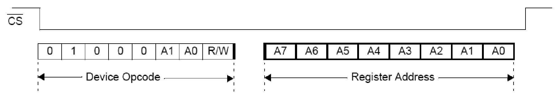
The MCP23S08 follows a specific protocol for the microcontroller to access its register set. (see diagram below). Once a register is addressed, the final data read or write operation can be performed as the next byte transfer, prior to CS going high.
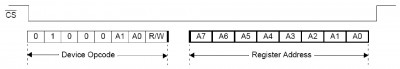 Addressing Internal MCP23S08 registers
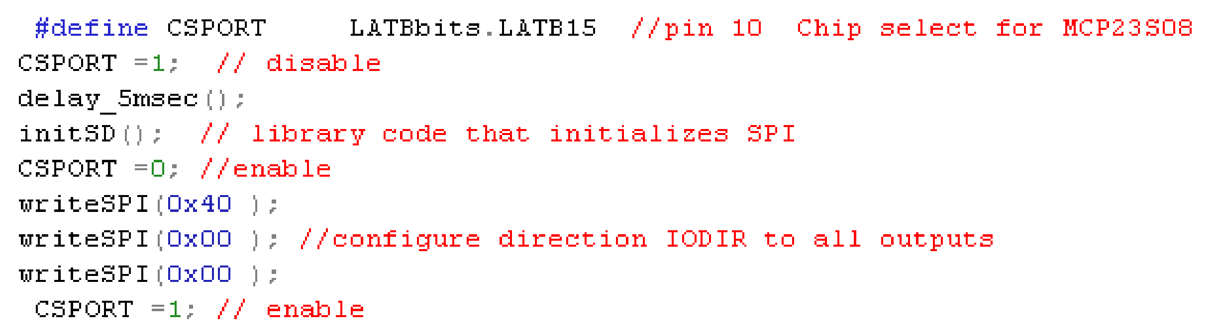
Initializing the MCP23S08 is very straightforward and appears in the Main function in demo project file Graphicstest.c (see initialization code). CSPORT is chip select for the MCP23S08 (pin 10 on Expansion bus). Critical functions used in initialization are:
• initSD() - initializes SPI for operation, library module referenced by Graphics.h • writeSPI (data) - writes eight bit data\command out to the MCP23S08, library module referenced by Graphics.h
Initialization Code
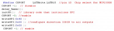
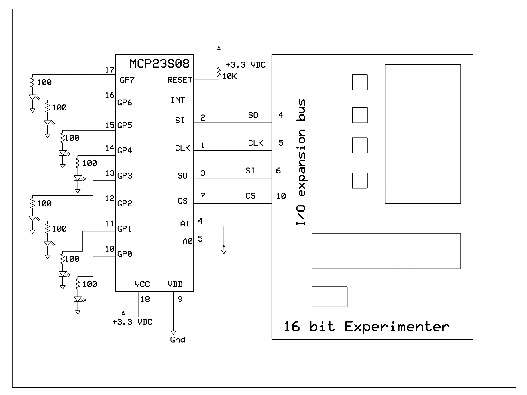
Once initialized, the SPI is then used to set up the MCP23S08 operation. First, we activate chip select CSPORT to initiate transfer with the MCP23S08 and then output opcode 0x40 to the SPI to access the MCP23S08 at address 0 for a write operation (reference schematic hook up diagram from part 1). The MCP23S08 pins A1, A0 are tied to ground, making the device address 0. The next Opcode 0x00 specifies the write address as IODIR (port direction setting control) and the final 0x00 sets up IODIR register for all MCP23S08 port bits to outputs. CSPORT is then set high to complete the transaction.
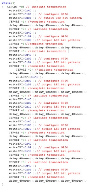
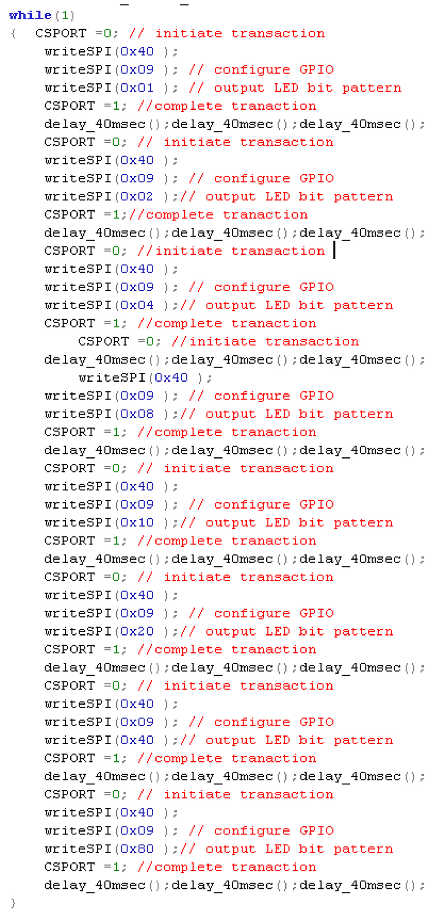
Once this is done, we just enter a continuous loop (see operating code) where each led pattern update is just a separate MCP23S08 transaction. Again CSPORT is activated, opcode 0x40 is again issued to indicate write operation to designated MCP23S08 at address 0, a new opcode 0x90 is then issued to address GPIO register to access port contents. And then finally, the LED pattern is issued to the port, before CSPORT is set high closing the transaction. This basic transaction scheme is repeated eight times within the loop continuously, between times delays, (to allow you to see the individual LEDs flash). The LED pattern changes from 0x01, 0x02, 0x04, 0x08, 0x10, 0x20, 0x40 and 0x80 before repeating.
Operating Code
One thing to keep in mind with the PIC24F microcontroller smaller packages, (like the one used in the Experimenter) is the Peripheral Pin select feature or PPS. With PPS, you need to configure the PIC24F pins on startup to access its internal peripherals like the SPI. This is essential for configuring the SPI pins to map to the I/O expansion bus, and exists in our demo at the start of the Main function in demo project file Graphicstest.c. The MCP23S08 device is very comprehensive in its capability -- that leaves you a lot of room to explore. What we've presented here is only the beginning. Microchip offers an even more challenging application note that uses the device to scan and report back key scan codes under interrupt for a 4X4 keypad. I hope this entices you to explore this device further and make it part of your Experimenter applications.
IO Expander demo 8 LED.zip Adding More Digital I/O to your 16-Bit Microcontroller Experiments - Part 1 The Hardware
The 16-Bit MicroExperimenter kit is available now and can be purchased from the Nuts & Volts webstore.
Purchase Kit Now!
The MCP23S08 will be available from the NV webstore on 5/21/10.
Comments