This final article explains how to use the interrupts and flags available in an MCP2515 CAN controller IC, and describes how device-to-device acknowledgments work on the bus. The acknowledgment bit in a CAN frame plays a key part in successful communications and identification of errors.
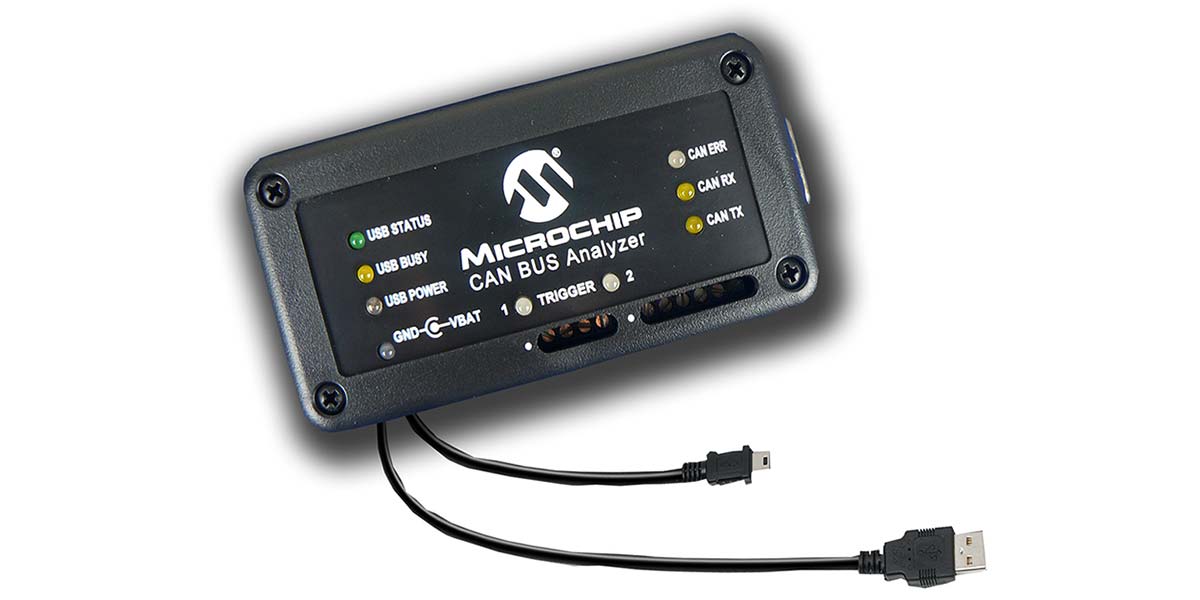
Although you can understand CAN controller interrupts and flags without a second CAN device, you will need one to experiment with interrupt-driven software. I use an inexpensive Microchip CAN BUS analyzer tool which comes with PC software that displays bus communications and sends CAN frames.(Figure 1 - shown above, Courtesy of Microchip Technology). This device accepts differential CAN bus or logic-level signals, and its PC software transmits and receives data via a USB connection.
My investigations use a true differential bus such as the one shown in Figure 4 in the first Nuts & Volts article in this series (December 2016). For commercial work, better — and expensive — analyzers can purposely create bus errors, record and play back bus frames, and so on.
Interrupts
Programmers often write code that runs in a loop and regularly tests a flag bit or I/O pin to determine whether a device needs attention and to take action if it does. The period between these software tests might range from a few milliseconds to hundreds of seconds depending on other tasks an MCU must perform. People and machines often require an almost-instant response, so most MCUs incorporate one or more interrupts. When an MCU receives an interrupt signal, it immediately stops any code currently running and transfers control to a separate program called an interrupt service routine (ISR). The ISR code disables the interrupt request input, runs code associated with the interrupting device, re-enables the interrupt input, and returns program control to the main program. Figure 2 illustrates the program flow along a time axis. Because interrupts may occur at any time, ISRs exist outside the main portion of a program. The asynchronous nature of interrupts can complicate testing because programmers cannot predetermine when an interrupt will occur.
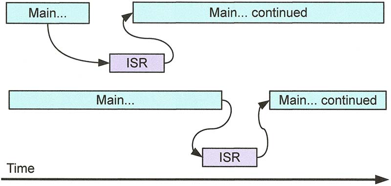
FIGURE 2. Timing diagram for an interrupt service routine (ISR). An interrupt can occur at any time, which can lead to debugging problems. Aim to keep ISRs short, and eliminate blocking code and calls to non-reentrant code.
The following program illustrates a simple ISR that turns on an LED when the input signal at mbed pin p12 changes from a logic 1 to a logic 0; a falling edge. (You can download all the software for this article and an extra program at the article link.) In the example below, the “infinite” while-loop statements cannot affect the LED called LED_irq. Only the ISR can do that, and it exists as a section of code separate from the main program:
//Interrupt Test  INTJT.cpp<br />
#include “mbed.h”<br />
   //header file for mbed MCUs
DigitalOut myled(LED1);<br />
   //define output for flashing LED<br />
DigitalOut IRQ_led(LED4);  <br />
   //LED for interrupt indication<br />
InterruptIn IRQ_pin(p12);<br />
   //Use mbed pin 12 as interrupt input
void LED_ISR()      //Interrupt service routine<br />
{    <br />
    IRQ_led = 1;    //Turn on LED4 on mbed module      <br />
}                   //End of ISR code<br />
 <br />
main()<br />
 {        <br />
    IRQ_pin.mode(PullUp);<br />
      //Use internal pull-up resistor<br />
    IRQ_pin.fall(&LED_ISR);<br />
      //IRQ_pin will detect a falling edge of  <br />
      //pulse. Specify thelocation of the ISR code<br />
    IRQ_led = 0;    //Turn off LED4<br />
    <br />
    while(1)       //Run this loop forever<br />
    {<br />
        myled = 1;     <br />
      //Blink LED1 to show this code runs<br />
        wait(0.1);<br />
        myled = 0;<br />
        wait(0.1);       <br />
    }             //End of while loop<br />
}                 //End of main
In this program, I identify two onboard LEDs and define mbed pin 12 as an interrupt input I call IRQ_pin. You may choose another name if you wish. The ISR — named LED_ISR — contains one instruction that will turn on LED4. In the main portion of the code, the IRQ_pin.mode(PullUp); statement turns on an internal pull-up resistor at the IRQ_pin so the input becomes a logic 1 if left unconnected. (You could use an external pullup resistor instead.) The statement IRQ_pin.fall(&LED _ISR); sets the mbed pin so it will cause an interrupt only when it detects a logic 1 to logic 0 edge. It includes the address of the LED_ISR code.
If you run this program and then ground mbed pin 12, LED4 will turn on. Nowhere in the main program does the MCU test the state of pin 12. When you use the online mbed tools and libraries, the mbed Cortex-M3 processor automatically disables interrupts when it starts an ISR and re-enables them when it leaves an ISR. Other MCUs such as those in the PIC families require ISR software to handle these tasks.
Interrupts for an MCP2515
Because we don’t know when a CAN controller will receive data, an interrupt can let an MCU immediately attend to the receiver buffers. The MCP2515 CAN controller provides one interrupt-output signal (/INT) at pin 12. The MCP2515 CANINTF (CAN Interrupt Flag) register holds flag bits for eight devices or events. A logic 1 bit indicates a request for service:
- RX0IF and RX1IF show when the corresponding receiver buffer has new data.
- TX0IF, TX1IF, and TX2IF mark the corresponding transmitter as having completed a transmission.
- ERRIF lets software know an error of some type occurred.
- WAKEIF lets an MCU know the MCP2515 has detected bus activity while in the low power “sleep” state.
- MERRF indicates an error occurred during transmission or reception of a message.
As explained earlier, software can read the CANINTF register value and test flag bits at any time to determine whether a device or event needs attention. (After the software takes action, it must reset the corresponding INTF-register flag bit to a logic 0.) The CANINTF bits alone will not cause an interrupt.
A program also must set the corresponding bit or bits in the CAN Interrupt Enable (CANINTE) register. The contents of this eight-bit register let us enable (logic 1) or disable (logic 0) interrupts as needed. Figure 3 shows the registers and pins the MCP2515 CAN controller uses to manage interrupts. (For clarity, I omitted details not pertinent to this article.)
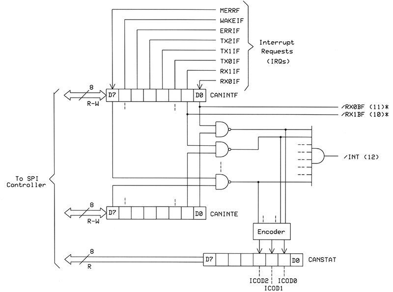
FIGURE 3. A simplified diagram of the registers, gates, and signals involved in MCP2515 interrupts. Pin numbers refer to the DIP version of an MCP2515 IC. Register read-write operations occur through an SPI connection with an MCU.
When a program sets the CANINTE register to 0x1F (000111112), only the three transmitter (TXnIF) and two receiver (RXnIF) flags may cause interrupts. For many applications, they suffice. Regardless of bits set or cleared in the CANINTE register, a program may always read all bits from the CANINTF register. (Refer to sections 6 and 7 in the MCP2515 datasheet for more information about the error and wake interrupts.)
When a program depends on the state of a CANINTF flag bit to, say, read a receiver buffer, ensure you clear that flag bit with an MCP2515 bit modify command after the program completes the read operation. This rule applies to all eight flag bits. A program cannot force a flag bit to clear if the condition that “raised” the flag still exists. Thus, if RXB0 receives data and you do nothing with it, the logic 1 remains set in the INTF register’s RX0IF bit.
The following program demonstrates how to set up code for an MCP2515 interrupt and how the code responds. In this case, the MCP2515 causes an interrupt only when it receives a message with ID 0x105. Each interrupt causes an LED to change its state. To test this software, you need a second CAN device to send a message with the ID 0x105. Ensure the MCP2515 /INT signal at pin 12 connects to the MCU’s interrupt pin (mbed P12 in this example).
It’s important to note the ISR only changes the LED’s state, sets a software flag (RXB0_Flag) to “true,” and clears the RXB0IF flag bit. So, the ISR takes only microseconds to service the interrupt. The main program periodically tests the software flag and then runs your application code to handle the RXB0 data. Of course, you could do the same steps in other ways. I aim to keep ISRs short:
/* Program CANJT4.cpp */
#include “mbed.h”<br />
   //header file for mbed MCUs<br />
#include “MCP2515JT.h”      <br />
   //header file for MCP2515 CAN IC<br />
DigitalOut myled(LED1);     <br />
   //define output for flashing LED<br />
DigitalOut IRQ_led(LED4);   <br />
   //LED for interrupt indication<br />
InterruptIn IRQ_pin(p12);   <br />
   //Use p12 on mbed for IRQ<br />
byte RXB0_Flag;<br />
   //Flag bit indicates RXB0 data
//Interrupt-service routine for RXB0 receipt of new data<br />
void RXB0ISR()                             <br />
{    <br />
  IRQ_led = !IRQ_led; //Toggle LED4<br />
  bitModify(MCP2515INTF, 0x01, 0x00);<br />
    //Clear RXB0 interrupt<br />
  RXB0_Flag = true;<br />
   //Set this flag to “true”         <br />
}                   //End of RB0ISR
//Main program starts here<br />
int main()                            <br />
{   <br />
reset();           //Reset MCP2515<br />
setMode(CONFIGURATION);      <br />
   //Put MCP2515 in CONFIG mode<br />
baudConfig(125);   //Set CAN bit rate to 125kbps<br />
setMask_0(0x3FF);  //Set RXM0 (Mask-0) to have<br />
                   // no effect<br />
setFilter_0(0x105); //Set RXF0 acceptance filter<br />
                  // F0 for ID = 0x105<br />
    <br />
setMode(NORMAL);       //Use normal MCP2515 mode<br />
bitModify(RXB0CTRL, 0x60, 0x20);<br />
   //Use only RXF0 filter<br />
bitModify(MCP2515INTF, 0x03, 0x00);<br />
   //Clear RX0 and RX1 interrupt flag bits    <br />
IRQ_pin.mode(PullUp);  //Use the internal pullup<br />
                       //resistor on mbed p12<br />
IRQ_pin.fall(&RXB0ISR);<br />
   //Set the IRQ_pin to dete a falling edge 1—>0<br />
IRQ_led = 0;       //Turn off IRQ indicator LED<br />
RXB0_Flag = false; //Clear this flag when<br />
                   // program starts<br />
bitModify(MCP2515INTE, 0x01, 0x01);<br />
   //Set RX0IE interrupt-enable bit to logic-1<br />
    <br />
while(1)          //Run this loop forever<br />
  {<br />
    myled = 1;   //LED-blink code to show<br />
                 // program working<br />
    wait(0.1);<br />
    myled = 0;<br />
    wait(0.1);<br />
        <br />
    if (RXB0_Flag == true)       <br />
        //Test to see if valid data has arrived<br />
      {                            <br />
        //Your data-handling code goes here...<br />
      }           <br />
  }     //End of while loop<br />
}       //End of main
Test Several Interrupts
If you set the CANINTE register so more than one condition will cause an interrupt (refer again to Figure 2), the ISR must test the CANINTF flag bits one by one to determine what event or events caused the interrupt. The ISR could use bitwise-AND operations to test the flag bits in any order. The flow chart in Figure 4 offers an example of this type of ISR which tests for an interrupt from RXB0, RXB1, and TXB0. The MCP2515JT.h file defines a one-bit mask for each of the eight interrupt flags, RX0IF, RX1IF, and so on.
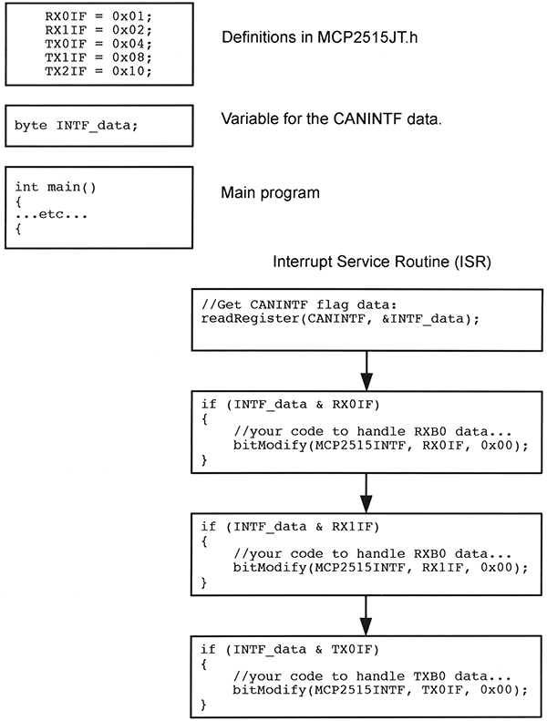
FIGURE 4. An ISR example in which an MCU tests interrupt flags for three devices in a "daisy-chain" arrangement. As a result, an interrupt from receiver buffer 0 has the highest priority because the software tests its interrupt flag first.
The mbed’s Cortex-M3 processor includes a Nested Vectored Interrupt Controller (NVIC) that lets programmers control as many as 240 interrupts with a priority from 0 to 255 for each. It takes quite a bit of study to understand the NVIC, but it’s available for complicated programs and real time operating systems (RTOSs). Find information about the Cortex-M3 processors on the ARM website at http://infocenter.arm.com/help/index.jsp.
Interrupt Tips
Keep all ISRs as short as possible because they “steal” time from a main program. In poorly written software when an ISR from a low priority device runs, it might inadvertently prevent a device with a higher priority from executing its own ISR. We call this a priority inversion, which you want to avoid. For more information, visit https://en.wikipedia.org/wiki/Priority_inversion.
Also, do not use non-reentrant functions such as printf or malloc in an ISR. Suppose a program starts to run a printf operation and gets part way through when the MCU receives an interrupt from device X. The device-X ISR also includes a printf statement. After the ISR completes its task, control goes back to the main program. Because your code can not re-enter the interrupted printf statement, you have a problem. The partially complete printf function in the main program fails. Check your compiler specifications for reentrancy information, and don’t write non-reentrant code! For more information, visit www.embedded.com/electronics-blogs/beginner-s-corner/4023308/Introduction-to-Reentrancy.
In addition, an ISR — really any program — must not include blocking code or code that could block following operations until another operation completes a task. Suppose you always expect two CAN messages, one right after another. The first message arrives and triggers an interrupt. The ISR gets the first message and then runs a loop to wait for the second message. If the second message never arrives, the program waits and waits, and waits. It never gets out of the ISR (Ref. 1).
Instead, programmers might write an ISR that saves the first message, increments a counter, and immediately returns to the main program. A second message would go through the same ISR actions. The main program could periodically test the counter for the value 2 and then process the two messages. The main program could include, say, a 100 millisecond clock that could cause an error interrupt if a second message hasn’t arrived during that period (Ref. 2).
If you don’t plan to use interrupts, code can run through a loop, monitor the CANINTF bits, take action based on the flag states, and then reset the flags. Just ensure you have set the CANINTE (CAN interrupt-enable) register to 0x00. This value prevents any flag bit from causing an interrupt at the /INT output (pin 12). Of course, if you leave this pin unconnected, there’s no concern about interrupts.
The MCP2515 provides two special outputs — /RXB0BF and /RXB1BF — you can use as individual interrupt or flag signals that indicate the respective receiver buffer has new information. These flag outputs operate independent of the CANINTE register bits. If you use these two flags, ensure your software clears them after you read the respective receiver buffer.
The MCP2515 also provides an interrupt code in the three read-only CANSTAT.ICOD bits, but I have never used them. The three-bit code presents interrupt information in priority order, so 0012 (the highest priority) indicates an error. The code 1112 identifies an interrupt from the RXB0 buffer. See the MCP2515 datasheet for details.
Acknowledge Errors
An important characteristic of CAN communications involves the acknowledgment of an error condition. To start this discussion, I’ll first give you an overview of a CAN communication. For clarity, I’ll discuss only communications that use a standard 11-bit identifier (ID). Let’s assume we have four CAN devices that each have one receiver ID filter set for 0X0C1, 0x02B, 0x0AF, and 0x0A0, respectively. For now, we’ll treat the values as “addresses.” Device C1 will send two data bytes — 0x0F and 0xC4 — to device AF. Figure 5 shows the logic signals that appear on the bus.
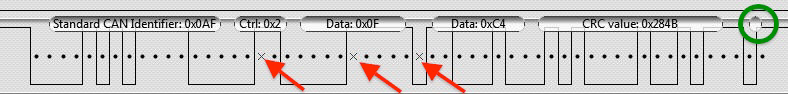
FIGURE 5. The logic analyzer information for the transmission of data bytes 0x0F and 0xC4 with a standard identifier of 0x0AF. The green circle identifies the acknowledgment bit. The three red arrows point to "extra bits" placed in the data by the sending CAN controller.
More generally, all CAN transmission begins with a logic 0 start-of-frame (SOF) bit, followed by the 11-bit ID (Figure 6). The remote transmission request (RTR) bit that follows the ID indicates a standard data message (logic 0) or an RTR (logic 1). Device 0x0C1 sends 0x0AF a standard message. A CAN controller will send an RTR message to request information from one or more devices. That transmission includes an address but no data bytes. You program a register bit to create an RTR message.
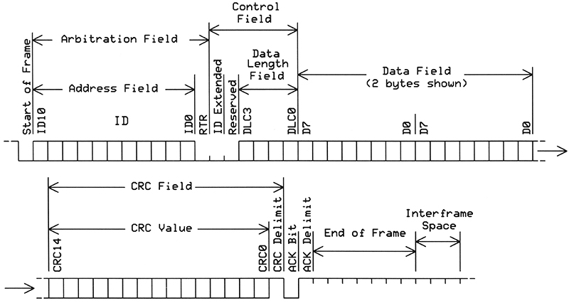
FIGURE 6. The arrangements of bits in a normal CAN transmission with an 11-bit ID and two bytes of data. Tick marks are included to clarify bit timing.
The CAN standard specifies a six-bit control field in which the four LSBs hold the data-length-code (DLC) that indicates the number of data bytes: 0 through 8 or 00002 to 10002. The original CAN standard reserved the two MSBs in the control field for future use. In the latest standard, one bit — labeled ID Extended — indicates whether a frame uses a standard 11-bit or an extended 29-bit identifier. One bit still remains reserved for future use.
Next, the CAN frame includes a 15-bit cyclic redundancy code (CRC) value calculated by the sending controller, followed by a logic 1 “delimiter” bit that ends the CRC field. After the CRC-delimiter bit, the sender transmits a recessive (logic 1) output and its receiver monitors the bus. Whether or not specifically addressed, all devices on the bus receive the frame and all calculate a CRC based on the data they received. They all use the same CRC algorithm.
Why do the “unaddressed” devices also need to calculate the CRC? It helps them detect controller problems. After the CRC calculations, each device compares its result with the CRC in the received frame. When the two match, a CAN device transmits a single-bit dominant (logic 0) acknowledgment (ACK) signal on the bus. If the CRCs do not match, a device puts out a one-bit recessive (logic 1) state.
Assume all receiving devices work properly and all put a logic 0 on the bus during the ACK period. The sender monitors the bus and expects this logic 0 signal. So, no CAN device reported an error and everything seems to looks good. (Keep in mind the acknowledgment only indicates a CRC match and not that a message was received successfully.)
Oops, a CRC Mismatch
What happens in a CAN controller when a received CRC and a calculated CRC don’t match? This situation provides a good example of the clever capabilities of CAN communications you cannot get with simple UART transfers:
- Say one CAN device (XYZ) calculates a CRC not equal to the CRC in a message. That error will cause it to keep its transmitter output in the recessive state during the ACK period. At the start of the ACK period, device XYZ detects a dominant state on the bus caused by other receivers that have no CRC mismatch. The difference between the dominant “CRC-OK” signal on the bus and recessive “CRC-mismatch” signal from device XYZ causes it to send an error frame (Figure 7) right after the ACK delimiter period.
- Now consider the case when all devices on a bus detect a CRC error. They all put a recessive signal on the bus. The sender expects a “CRC-OK” dominant signal instead. The recessive signal indicates the sender either calculated an incorrect CRC or transmitted an incorrect CRC. So, the sending device knows it has a problem and reports an error.
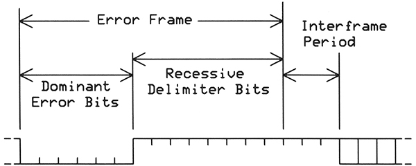
FIGURE 7. An error frame includes six dominant bits followed by eight recessive bits in an error delimiter. Only an error frame purposely puts this arrangements of bits on a CAN bus.
Other types of errors can occur at other times and also cause transmission of an error frame. The receipt of an error frame may trigger a resend of the original message. CAN controllers can count errors and cause an interrupt if they exceed preset limits. However, the CAN bus has proven very reliable and data errors rarely occur, although you could experience signaling problems in a poorly designed bus topology.
What’s an Error Frame?
As shown in Figure 7, an error frame comprises a dominant state (logic 0) for six clock periods followed by a recessive state (logic 1) for eight clock periods. A three-bit recessive interframe space separates the error frame bits from any other information that might next appear on the bus. Some people say the six dominant states “violate” the CAN specification, but they’re simply a different part of the standard. The so-called violation occurs because CAN controllers allow only five consecutive bits at the same logic level — recessive or dominant. So, how will a CAN message handle a transmission of 0xFF followed by 0xFF, or 16 logic 1 bits in a frame?
A CAN bus requires a way to have devices stay “locked” on the clock frequency that governs the bit rate. So, a transmitted message provides synchronization information during logic-level transitions. To ensure often-enough transitions occur, a CAN controller automatically inserts or “stuffs” an extra bit in the communication as needed. Look at the transmission of 0xFF and 0x00 (Figure 8).
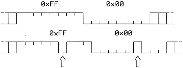
FIGURE 8. To send a message with 0xFF and 0x00, a CAN controller inserts stuff bits (arrows) so a sequence of bits includes no more than five bits with the same state. This example does not take into account any bits prior to the first 0xFF byte. Can you describe an algorithm to remove stuff bits at a receiver?
The controller allows only five bits with the same logic state. If the sixth bit has the same logic level, the controller inserts a bit with the complementary logic level and then the sixth bit follows. Thus, you will see a maximum of five same-level bits in a CAN message (see Figure 5 also). The six-bit recessive error frame includes no stuff bits and thus provides a way to signal an error condition to other bus devices.
You now have a good introduction to how the CAN bus and CAN controllers operate, and how communications occur. You might find a use for this bus when you need reliable high speed communications without a lot of complicated hardware or large protocol stacks.
I find the MCP2515 CAN controller easier to use than many CAN controllers built into MCUs and recommend it as a good IC to use as you investigate CAN capabilities. I welcome comments and questions at [email protected]. NV
Resources
ARM Cortex-M3 Nested Interrupt Vector Controller (NVIC):
http://infocenter.arm.com/help/index.jsp
Reentrant Code Tutorial:
www.embedded.com/electronics-blogs/beginner-s-corner/4023308/Introduction-to-Reentrancy
Priority Inversion:
https://en.wikipedia.org/wiki/Priority_inversion
References
1. "Non-Blocking Code," Engscope
https://web.archive.org/web/20161223103200/http://www.engscope.com/pic-example-codes/non-blocking-code
2. Titus, Jon, "The Hands-On XBee Lab Manual," Newnes Press, Waltham, MA, USA. 2012, pp. 228-246. ISBN: 978-0-12-391404-0
www.amazon.com/Hands--XBEE-Lab-Manual-Communications/dp/0123914043
3. Voss, Wilfried, "A Comprehensible Guide to Controller Area Network," Copperhill Media, Greenfield, MA 2008. ISBN: 978-0976511601
http://copperhilltech.com/technical-literature
4. Microchip MCP2515 datasheet, DS21801G.
ww1.microchip.com/downloads/en/DeviceDoc/21801e.pdf
Downloads
What’s in the zip?
Source code
Non-Blocking Code_Engscope.pdf
Paper on Non-Blocking code from Engscope.com Note that Engscope.com is no longer online.