When I was a kid in the ‘50s, my dad bought me a No. 8 1/2 Gilbert Erector Set for Christmas. It came in a sturdy metal box painted bright red, and was the start of my lifetime passion to build things.
The Big Picture
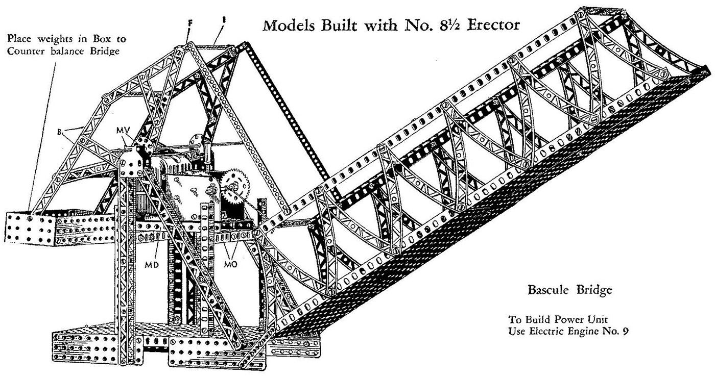
Back then, there were many different sizes of Erector sets, from the simple No. 1 1/2 to the complex size of 12 1/2 and beyond. Each version had more and different parts, and included the most fantastic manuals with dozens of beautiful illustrations of the exciting things to build like lift bridges, beam engines, drilling rigs, and the ultimate Giant Ferris Wheel. Figure 1 shows a typical illustration.
FIGURE 1. The Erector Set manual had dozens of illustrations of exciting things to build like a beam engine or this Bascule bridge.
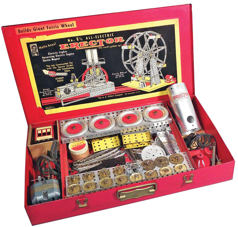
Figure 2 is just like the set I had as a kid. It contained no less than 253 parts plus 357 nuts and bolts to hook everything together. However, the real magic of the set was the lack of step-by-step assembly instructions. There were none. The manual had intricate drawings of the things to build, but I had to figure out the exact assembly sequence using my imagination. It was a great learning experience.
FIGURE 2. This set was one of their best sellers: the No. 8 1/2, which I had when I was a kid and is still available on eBay.
Unfortunately, Gilbert Erector Sets are long gone from the marketplace due to many factors. Luckily, many vintage sets are still available online and in antique stores for a reasonable price. Some are in poor condition with rusty parts that need some TLC, but occasionally you find primo sets that are ready to use or that you just have to get. Recently, I saw a beautiful No. 12 1/2 on eBay that I was sorely tempted to buy. We’ll see.
Building the Ferris Wheel
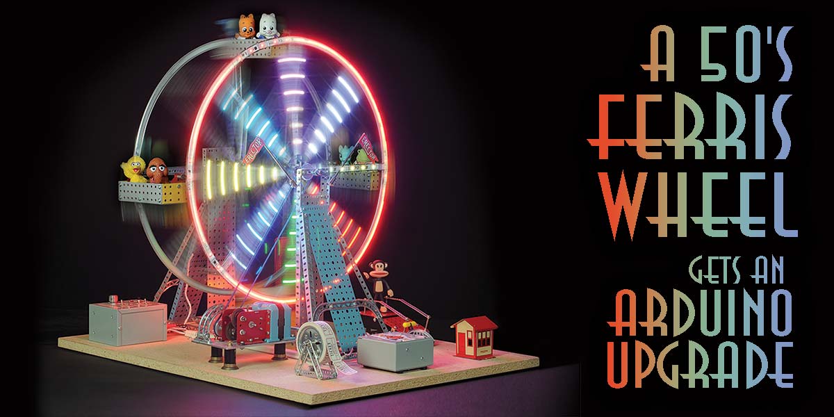
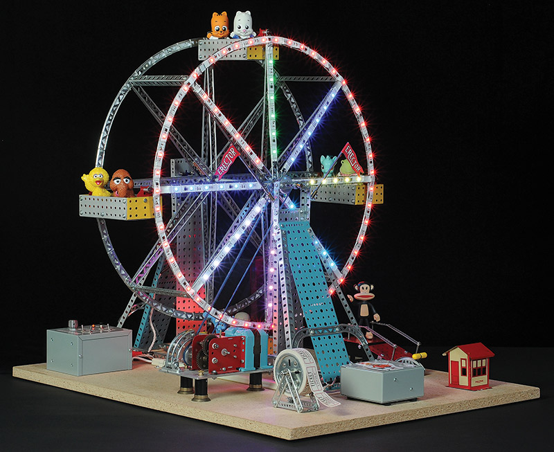
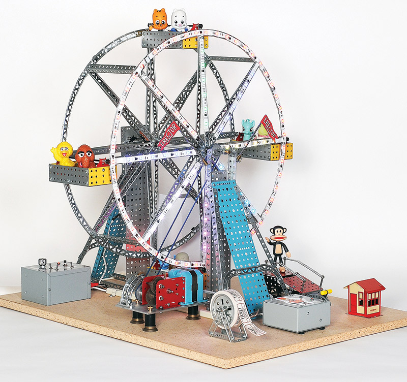
Okay, enough of the reminiscing. Let’s get on with how I built the Giant Ferris Wheel and added some modern components to enhance it, like an Arduino microcontroller. Figure 3 shows the end result.
FIGURE 3. I recently built this motorized Ferris Wheel from a vintage set and added flashing LEDs and a carnival sound track.
After several months of searching online for a suitable No. 8 1/2 set, I found a decent looking one for $150 on eBay. When it arrived, I was a little disappointed because the steel girders were dulled by oxidation; definitely not as bright as they looked in the listing. However, after spending the day with a package of #0000 steel wool and a lot of elbow grease, they polished up quite nicely.
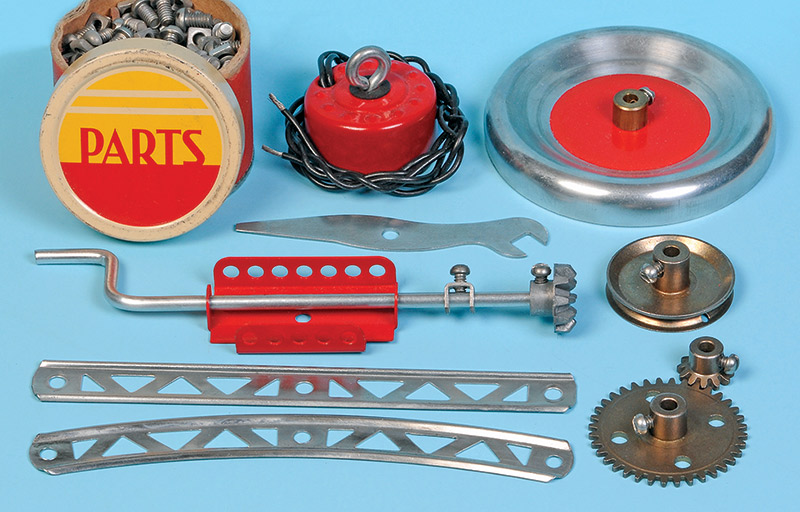
Figure 4 is a sampling of the restored parts. Notice the cool lifting magnet in the upper center. Its resistance is 12 ohms and it operates on three batteries: 4.5V/12 ohms = 375 mA.
FIGURE 4. Here are several typical parts including a 5” girder, 5” curved girder, 3” disc wheel, and a cool electromagnet.
Another favorite component in the larger sets was the “Motor.” Refer to Figure 5.
FIGURE 5. The Erector all-metal 110 VAC type A49 motor has extra holes for various gear ratios and reversible operation.
It was not a wimpy plastic DC motor powered by two AA cells, but an all-metal, multi-speed, reversible, 110 VAC power mover. Just add a pulley and you had a winch that could do some real work.
The motor that came with the set I bought had some chipped paint, was a little grimy, and needed a new power cord, so I took the opportunity to completely refurbish it to its former glory. Listening to the sound of its newly oiled gears going round and round was music to my ears. Plus, it was reversible with the movement of a small handle that engaged a sequence of gears. I remembered back to when I first learned how to set up gear ratios in order to slowly raise a lift bridge or rotate a Ferris wheel.
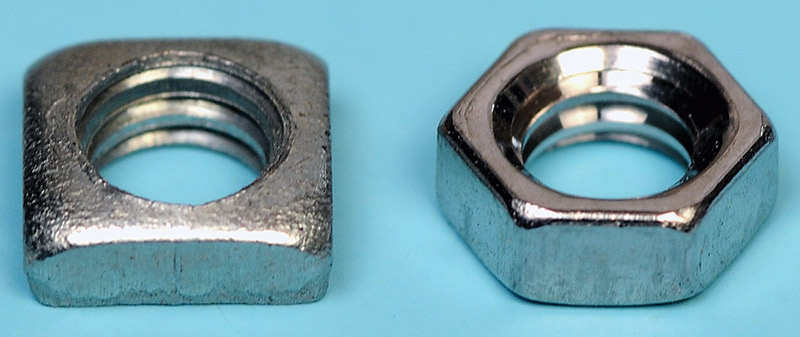
As some of you might recall, the 8-32 nuts that came with the sets were square instead of hexagonal and sometimes were painful to hold and tighten on the bolts. The square edges would jab into your fingertips (Figure 6).
FIGURE 6. The set’s 8-32 square nuts fit nicely into tiny spaces, but are painful to tighten with your fingers compared to hex nuts.
Therefore, my first step was to set aside the original nuts and buy several gross of modern small pattern hex nuts. No more sore fingers!
It took me a couple of days to build the basic Ferris wheel structure and get it spinning freely on the axle. The manual showed a pulley mounted on the motor and another larger one on the wheel axle, connected together by a long loop of string that was supposed to act as a belt. No joy! The string slipped on the pulleys no matter how much tension was applied. Then, I recalled a toothed belt and pulley arrangement that I had used during my aerospace days. So, I looked them up in the PIC Design catalog.
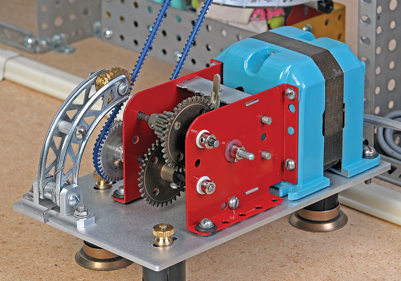
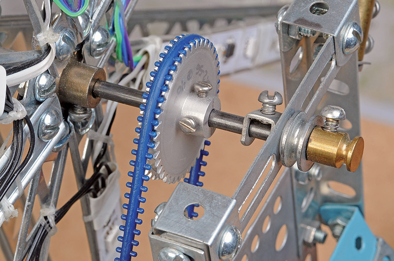
Yikes. The price was $29 for the belt and $54 for two mating toothed pulleys. I debated whether I should simply use a belt made of o-ring type rubber, which probably would have worked fine. Figure 7 clearly illustrates that I caved in and spent the money for the cool looking blue belt. The final rotation rate was about 5 RPM.
FIGURE 7. The manual showed a drive belt made of string but it slipped, so I substituted a cogged belt. Sweet!
Adding Bells and Whistles
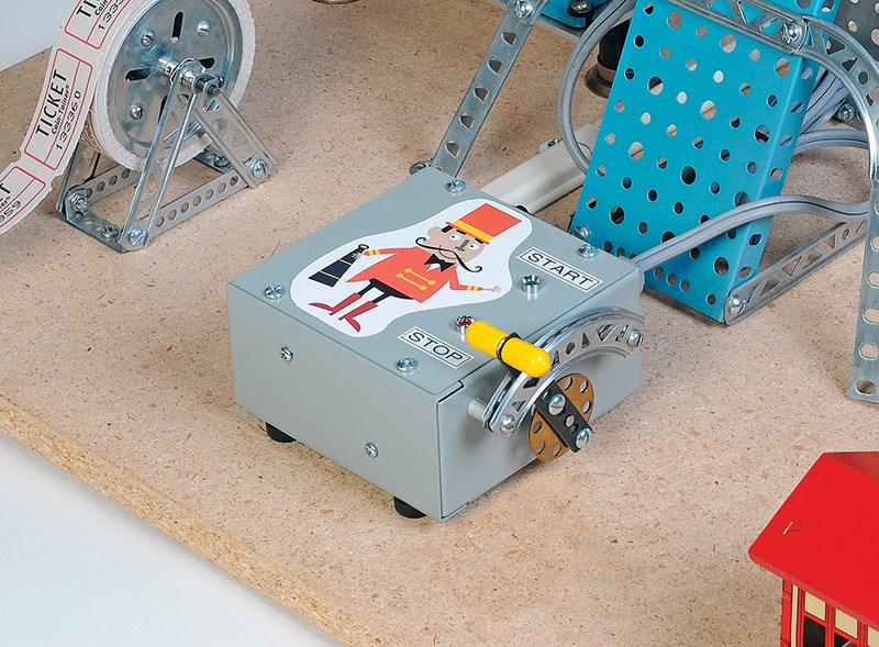
Figure 8 shows how I used several 2-1/2“ curved girders to build a start/stop lever on the control box. The action sort of duplicates the actuation of the clutch mechanism in a real Ferris wheel, instead of using a modern toggle switch.
FIGURE 8. My start/stop lever switch emulates the manual clutch lever used on old-fashioned carnival rides.
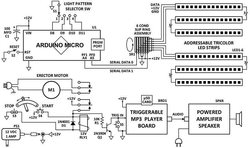
Figure 9 is the schematic of the whole system including the latching relay circuit for the motor. The start/stop lever also triggers the newly added MP3 player board to start the carnival music.
FIGURE 9. An Arduino microcontroller sends 24-bit serial data to the tri-color LED strips to produce various flashing patterns.
A while back, someone suggested that a carnival-like sound track would be a good addition, so I did it. The music file came from the Internet and was transferred to a SparkFun triggerable MP3 player board using Audacity. The MP3 board was not made to directly drive a speaker, so I dug out an old RadioShack powered speaker that I’ve had for years and mounted it on the rear corner of the baseboard. I never throw anything away because you never know when you’ll need it! Although it took quite an effort to add the sound track to the project, I’ll have to admit that the carnival music made a big difference. It was just like you were walking down the midway.
One day when I was in RadioShack, I stumbled across a bunch of addressable tri-color LED light strips for a vastly reduced price on the closeout rack. I figured the lights would look great on the Ferris wheel, so I attached them around the rim and down the spokes with lacing cord. The strips require a 24-bit serial data stream to control the brightness and color of the tri-color LEDs. I chose an Arduino to do the job because it was easy to program, had enough memory, and was pretty small.
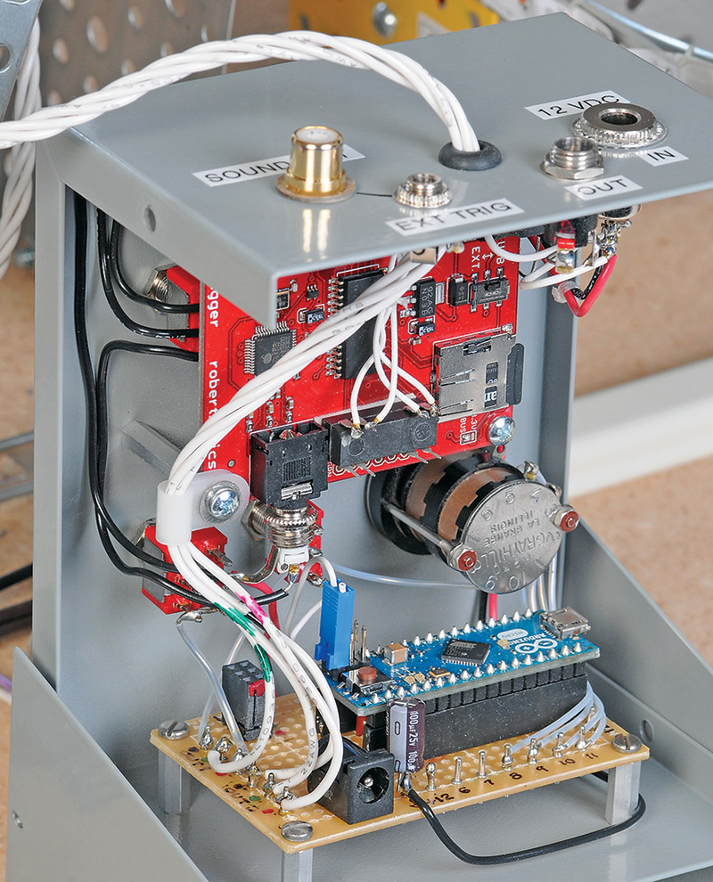
Figure 10 is an interior photo of the newly added chassis box containing the Arduino and MP3 player. As you can tell, the project was rapidly spiraling out of control. The bells and whistles were taking over.
FIGURE 10. The red SparkFun triggerable MP3 board plays carnival music to give the project the feel of the midway.
Now the big question ... how to get power and data to the rotating LEDs? A slip ring rotary joint was the answer. When I was working in aerospace, mil-spec slip ring assemblies were very expensive. However, a quick look on eBay saved the day. For under $10, I found a commercial six-conductor plastic unit from China, and it got here in less than a week. I can’t help but wonder how they can make a profit.
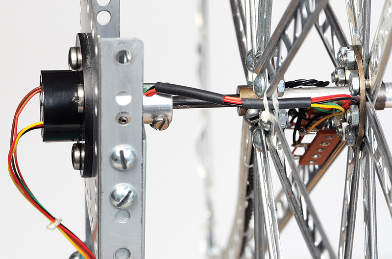
Figure 11 shows the slip ring assembly installed on the main axle of the wheel. Refer to the schematic for the wiring. Two of the conductors were used for the serial digital signals from the Arduino to the LED controller chips.
FIGURE 11. A six-conductor slip ring assembly from China transmits power and data to the LEDs on the rotating wheel.
Actually, I think I spent more time playing around with different lighting patterns than anything else in this project. I had fun generating a number of sketches that produced hypnotizing patterns of colored lights. It was hard to stop playing with it. (BTW, the Arduino code is available at the article link.)
I won’t go into any detail about the code here because it’s pretty simple and most of it was “example code” for the discontinued LED strips from the Shack. SparkFun and Adafruit have much better addressable LED strips now, plus example code to run them.
Bells and Whistles, Phase 2
I thought that adding the lights was the end of the project until one evening when I was proudly showing it to my wife, she commented, “That’s real nice but what it needs are some cute little characters riding in the cars.” Garf! Unfortunately, she was right. So, I headed to the toy store and found eight properly-sized candidates, including Big Bird.
I glued them down in the front of the cars so you could see their faces as they went round and round. The only problem now was that the cars were tilted forward, not level. I hate it when things are not level. So, I added a number of hefty steel nuts in the rear of each car until they were all perfectly flat. Success!
I started the motor and the “cute” little characters went half way around and promptly came to a dead stop. What the heck? After an intensive 10 minute failure mode analysis, I discovered the core problem. Each car now weighed a different amount because of the different sizes of the characters and quantity of steel nuts. This situation unbalanced the big wheel and overwhelmed the torque of the Erector motor. The answer: more steel nuts. Finally, it was perfectly balanced and rotated very smoothly. Done, done, and done!
All my friends were impressed with the operation and the kids were mesmerized by the flashing lights and carnival music. It was well worth the effort. However, my wife still had one more thing to say about the project. “I love how it turned out,” she said, “but where are you going to find the room to store it?”
Final Thoughts
It was fun working again with the Erector Set metal girders, axles, and especially the motor. It’s sad that sets like these are not economically feasible anymore. I think that kids are missing out with the snap together, no-thinking-required plastic kits of today. Fortunately, vintage Erector sets are still available.
I think that buying one and building a project like the Ferris wheel or a Bascule bridge with your kids or grandkids would be a kick. I hope you will truly consider it. NV
PARTS LIST
DESIG
COMPONENT
SUPPLIER
BELT
Cog Drive Belt, 33"
PIC Design, FA-336
BOX1
Chassis, 3x4x5, Aluminum
Digi-Key, L104
BRD1
MP3 Player Shield
SparkFun, DEV-12660
C1
Capacitor, 100 mfd 25V
Digi-Key, P10269
CHAR1-9
Characters, Cartoon
Toys-R-Us
D1
Diode, 1N4001
Digi-Key, 1N4001DICT
LED1-6
Tricolor LED Strips
RadioShack, Closeout
NUTS
3/8-16 Steel Nuts
Home Depot
PS1
Power Supply, 12V 1A
RadioShack, Vintage
PULLEY1,2
No-Slip Pulley, 40 teeth
RadioShack, Vintage
Q1
NPN transistor, 2N3904
Digi-Key, 2N3904FS
R1
Resistor, 10K
Dig-Key, 10KQBK
RLY1
Relay, 12V, DPDT
RadioShack, 2750043
S1
Rotary Switch, Four-position
Junk Box
S2
Toggle Switch, SPDT
Digi-Key, CKN1023
S3,4
Microswitch, Roller, SPDT
RadioShack, 2750017
S5
Pushbutton, N.O.
RadioShack, 2751556
SET1
Erector Set, #8 1/2, c1950
eBay
SPKR
Powered Speaker/Amp
RadioShack, Vintage
SR1
Slip Ring, Six-conductor
eBay, China
U1
Arduino Micro w/Headers
Adafruit
A handy reference book is Greenberg’s Guide to Gilbert Erector Sets shown in Figure A. It has full color pictures of every set and even has a listing of each and every part in all the different sets. For example, in 1950, a No. 10 1/2 set contained (52) 10” girders, (26) 5” curved girders, (4) 7” axles, (4) 3” disc wheels, (271) 8-32 square nuts, and hundreds of other parts. If you’re interested, Wikipedia has a brief history of Erector Sets on their website.