It's said that need is the mother of invention. Recently, I had to troubleshoot some IR obstruction sensors used with my garage door opener. In order to operate in bright daylight, they use pulsing infrared light beams to detect an obstruction near the garage floor. I installed a new pair and aligned them correctly. They worked, but only intermittently. I checked the obvious things like loose connections and correct wiring. When it was warmer, they worked okay, but when it got colder, they were intermittent even when no obstruction was present. This prevented the garage door from going down and caused a reversal.
Since the output of the IR sensor unit was a pulsed waveform, I needed to look at the output waveforms to determine what was wrong. I thought about dragging my Heathkit two-channel 20 MHz CRT oscilloscope out to the garage and hooking it up, but decided there had to be an easier way. I thought there had to be a simple low cost alternative for solving my problem.
This is where the mother of invention part comes in. I had a program called Soundcard Scope by Christian Zeitnitz. This would work, but might cause serious damage to my HP laptop if the input were overloaded. Also, it would be nice to select input voltage ranges as needed. What I decided to implement was an interface circuit that would allow me to use my external microphone input and Soundcard Scope program to observe low frequency waveforms from my garage door obstruction sensors.
I designed the interface circuit to have a very high input impedance (10 megohms), four range selections (200 mV, 2V, 20V, and 200V per division), a buffered protected output, inexpensive RCA phone jack input connectors to work with low cost “homebrew” probes, BNC to RCA adapters to allow use with standard oscilloscope probes, and an 1/8” stereo patch cable to connect the interface module to the laptop external microphone jack.
Theory and Operation
Please refer to Figure 1 (schematic) for this discussion.
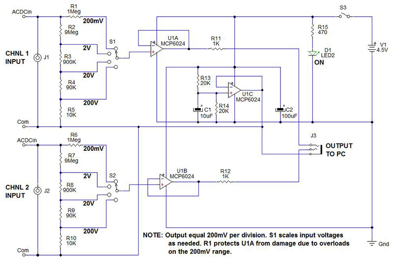
FIGURE 1. PC oscilloscope circuit.
The PC oscilloscope consists of two components. The first is a PC, laptop, tablet, or tower. The second one is the two-channel probe interface circuit that was designed to scale the input voltages as needed, and protect itself and the laptop from overloads and damage.
The inputs connect to the junction of R1, R2 (channel 1), or R6, R7 (channel 2). The rest of this discussion will pertain to channel 1, understanding that channel 2 is identical in function and operation.
When selector switch S1 is at the 200 mV setting, the input voltage is connected to the input of U1A via R1. U1A is used as a unity gain buffer. R1 limits the input current to a safe level that can be clamped by the internal MCP6024 protection diodes (±2 mA).
Therefore, any voltage less than 2,000 volts will be safely handled by the U1A inputs.
The output of U1A passes through R6 and R10 (not shown) to the 1/8” (3.18 mm) stereo output jack. This limits the output current to 6 mA if both outputs were shorted. That is well below the 20 mA rated output current.
S1 connects the input of U1A to a standard 10 megohm divider network. The nine meg, 900K, 90K, 10K 1% resistors scale higher input voltages into a manageable 200 mV range. I had trouble finding the resistors for the divider network as described, but was able to find these values which provide the same .001, .01, .1 divide ratios: 9.09 meg, 909K, 90.9K, 10K + 100 ohms. This alternate divider version is shown in Figure 2.
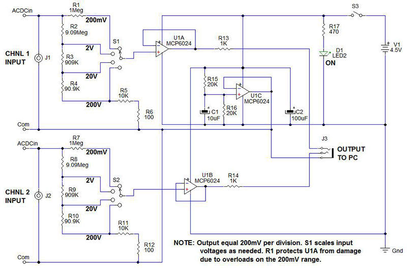
FIGURE 2. Alternate divider network.
By setting the Soundcard Scope to 200 mV per division, the divisions will now be equal to the setting of switch S1. The full range of the scope display will be plus or minus 1V, 10V, 100V, or 1,000V. This is useful for measuring higher voltage signals.
There's a frequency limit to the Soundcard Scope. This is due to the sampling frequency of the 16-bit or 24-bit (depending on your computer hardware) A/D used in the sound card, which is 44.1 kHz. It's good to only about 20 kHz, so good for most audio signals and lower frequency signals like the garage door sensors. It works well with PWM motor drive signals below 20 kHz, LED and fluorescent lighting ballasts, and other lower frequency signals.
I tried it out with my homebrew function generator (see Figures 3 and 4) to see how well it performed over a frequency range from 1 Hz to 40 kHz.
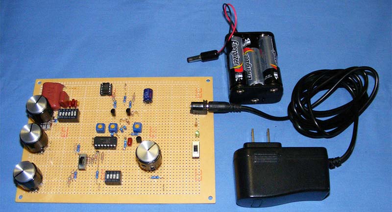
FIGURE 3. Sine, square, and triangle function generator.
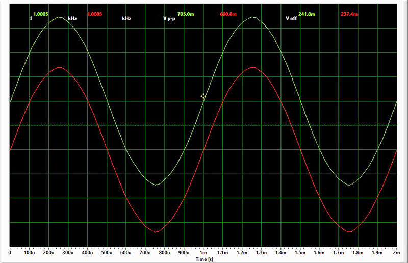
FIGURE 4. 1 kHz at .67% THD.
The results showed it worked well for sine waveforms up to 5 kHz, and up to 20 kHz for square and triangle waveforms. The other limitation of the PC o-scope is that the PC mic inputs are capacitively coupled, thus limiting low frequencies below 8 Hz and no DC voltages to be measured.
Op-amp U1C acts as a Vdd/2 voltage reference that is connected to the bottom of the input divider network and the output common. This centers the output of U1A and U1B at Vdd/2 and 0V with respect to the common output. The interface is powered by three AAA batteries. They last a long time due to the very low current that’s being drawn by the MCP6024. It's less than the current drawn by the power indicator LED D1.
The entire interface circuit draws only about 10 mA when on. The unused op-amp U1D is connected as a unity gain buffer, and the + input is connected to the output of U1C, or Com.
Building the PC O-Scope
The intention was to use inexpensive readily-available parts to build the PC two-channel o-scope. All of the resistors are metal film 1% for the input resistive divider, as well as the R15, R16 reference divider. J1, J2 are standard RCA female chassis mount jacks. J3 is a 1/8” stereo jack. Nearly any type of case could be used to house the circuit. I chose a SERPAC Model 032 plastic case left over from a previous project.
The board was sized to use the mounting bosses in the case. The three jacks were mounted to the side walls of the case. The AAA battery holder lays atop of the PCB and is held in place with a layer of packing foam rubber. The enclosure machining and case labels are shown in Figures 5 and 6.
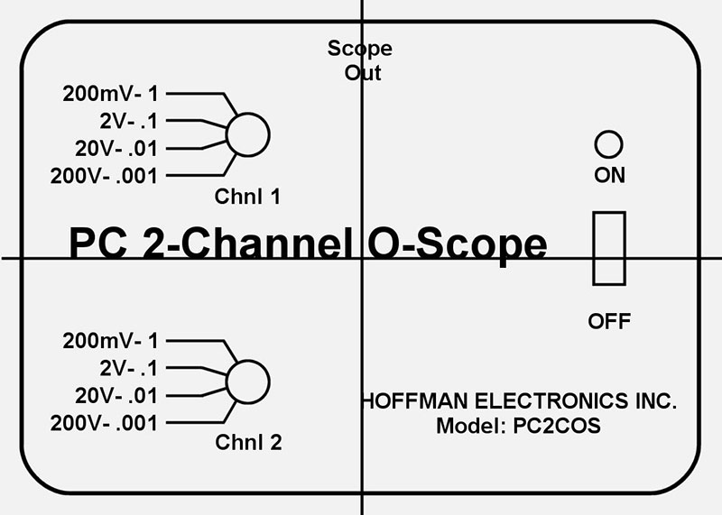
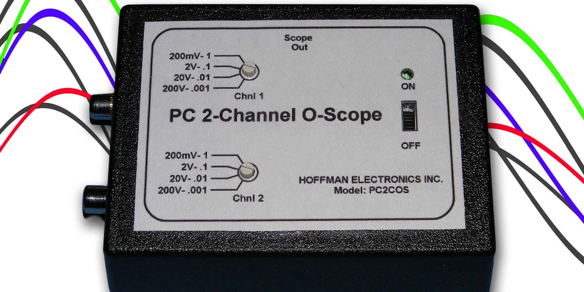
FIGURE 5. Machining label.
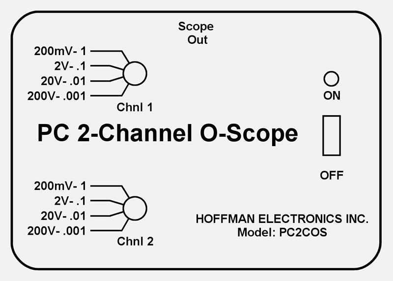
FIGURE 6. Enclosure label.
The Gerber files for a two-sided PCB layout (Figure 7) are available in the article downloads.
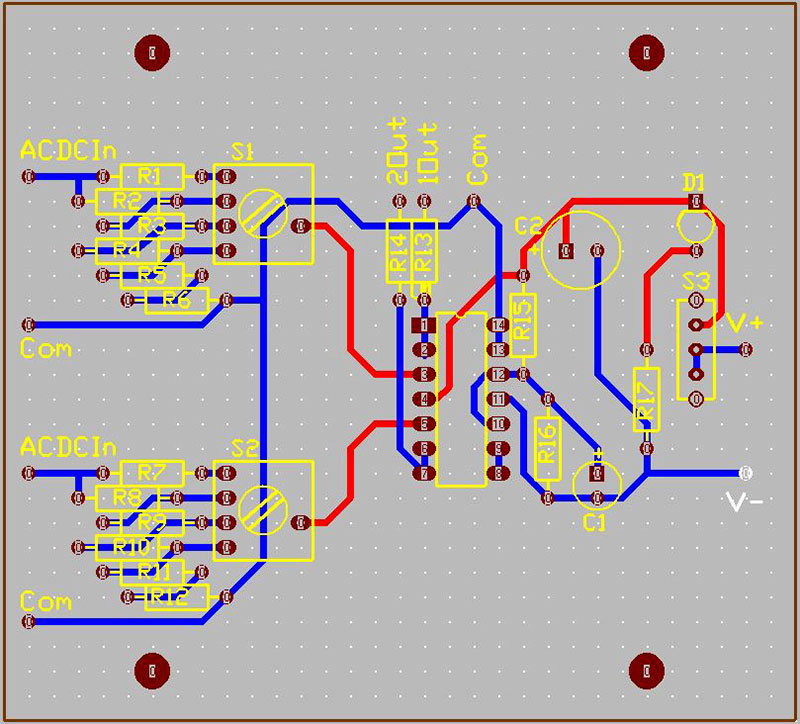
FIGURE 7.
The machine label has two center lines used to orient the label on the enclosure. Measure to locate the center point of all four sides of the enclosure near the edges. Align the machine label with the marks, then attach it with tape as shown in Figure 8.
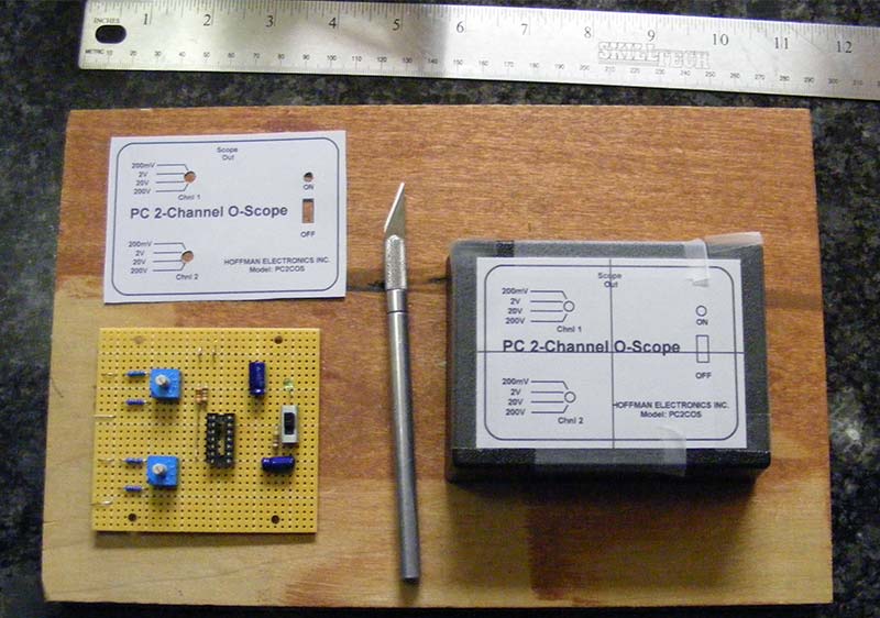
FIGURE 8.
After the machining is complete, remove the machining label and replace it with the enclosure label. Use adhesive laminate over the label to protect it. Leave a .25” border of the laminate around the edge of the label. Use double-sided tape or poster tape on the back of the label to secure it to the enclosure. Cut out the holes in the label using an X-acto™ knife. Use the holes to align the label on the enclosure. Burnish the laminate label edges and the poster tape to the enclosure.
For the build, point-to-point wiring was used on a prototype board from RadioShack, cut to the desired size to fit in the enclosure. The components were laid out and positioned the same as on the PCB layout in Figure 8.
After wiring and testing the circuit board, the jacks were installed into the enclosure and then wires were connected from the board to the jacks. The assembled unit is shown in Figure 9.
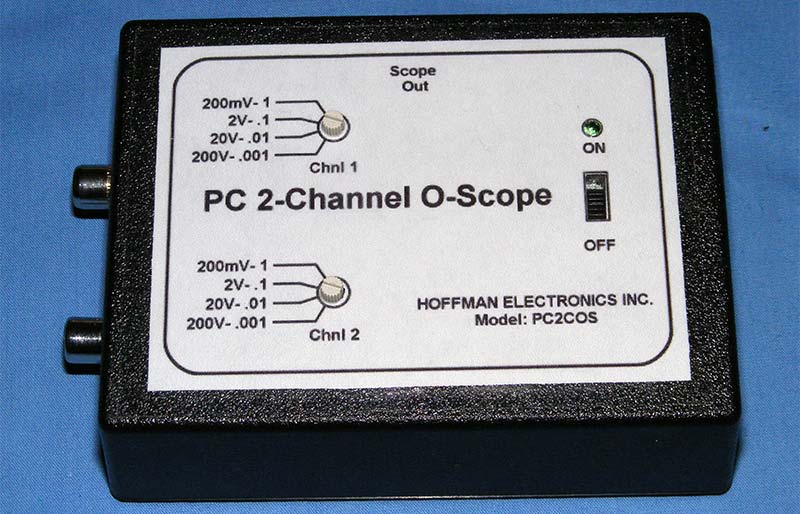
FIGURE 9. Assembled unit.
Though commercial oscilloscope probes can be used with the PC o-scope, I thought it would be nice to have some rugged customized probes more suited to automotive and project testing. Figure 10 shows some of my homebrew and commercial probes.
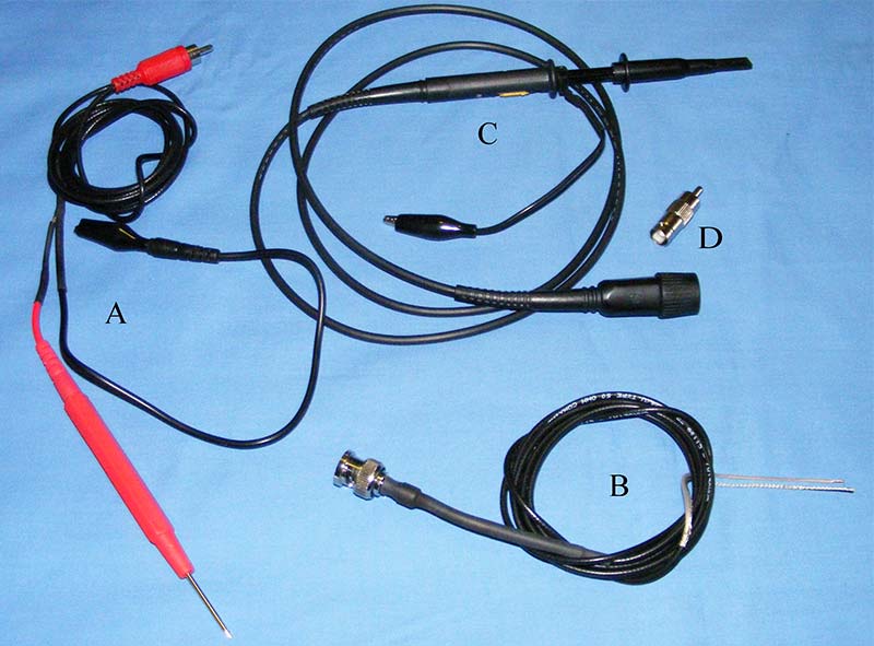
FIGURE 10.
First, I wanted to be able to connect them to test points that may be a few feet apart. Second, it was desirable to connect different types of probe attachments to the probe ends. What was chosen were multimeter probe leads that would allow for attaching a test probe, alligator clip, or spring-hook probe ends (Figure 10A).
To minimize noise, coaxial cable was used for the signal. The ground shield end had a multimeter test lead end soldered to it that allows for extended test hook-ups and attaching a probe, alligator clip, or spring-hook probe end.
Figure 10B shows a cable with a BNC connector on one end and the other end stripped and tinned to be connected to either probes, alligator clips, or spring-hook connectors. Figure 10C shows a commercial oscilloscope probe with a BNC connector. Figure 10D shows a BNC to RCA adapter used to transition the commercial probe, or the probe in Figure 10C to the PC scope unit.
Using the PC O-Scope
Using the PC o-scope is very straightforward. Refer to Figure 11 for the following discussion.
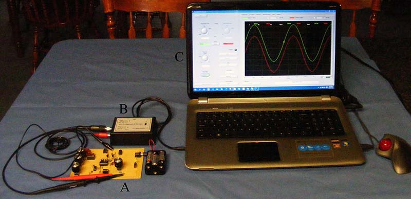
FIGURE 11.
Connect the output of the PC o-scope (the 1/8” stereo jack) to the microphone input jack of your laptop, desktop, or tablet computer (Figure 11B).
Make sure you have installed the Soundcard Scope Version 1.46 on your computer (www.zeitnitz.eu/ scope_en; click on scope 1.46) and then open it. Next, connect the desired scope probes to the inputs of the PC two-channel o-scope.
I connected the probes to my homebrew function generator (Figure 11A). Turn on the PC o-scope and the function generator. Adjust the function generator to 1,000 Hz, then set the PC o-scope channel 1 and channel 2 input selector switches to the 2V-X.1 position.
On your computer oscilloscope display (Figure 11C), set the amplitude CH1 to 100 mV/Div, click the sync box between CH1 and CH2, set the Time/Div to 2 mSec/Div, and set the trigger to auto, rising, channel 1, threshold = 120m. The screen should appear as seen in Figure 12.
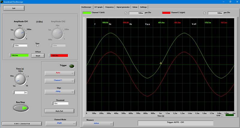
FIGURE 12.
If you click on the settings tab, then on the save settings button, you can save the Soundcard Scope settings as an .XML file to easily restore them for future use. Give them a name related to the task that they were used to perform; for example, Fnctn Gen 1.
That pretty much wraps it up. Figure 13 shows a Lissajous figure made by 60 Hz AC line noise in channel 1 and a 120 Hz sine wave from the function generator in channel 2.
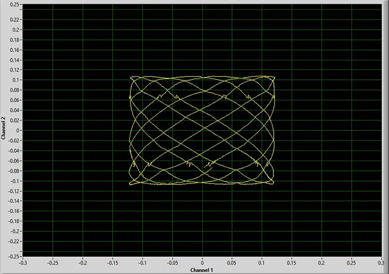
FIGURE 13. Lissajous figure (X-Y plot).
A Lissajous figure is basically an X-Y plot of the signals in the CH1 and CH2 inputs.
Another interesting thing is to click on the frequency tab and explore the different frequency domain representations of a sine, triangle, or square wave. The descending amplitude peaks of the frequency multiples indicate the mix of different sinusoidal frequencies and amplitudes that would need to be added together to produce the waveform, like a triangle or square wave.
Figure 14A shows a 1 kHz square wave and Figure 14B shows the FFT plot of the harmonic sine wave amplitudes.
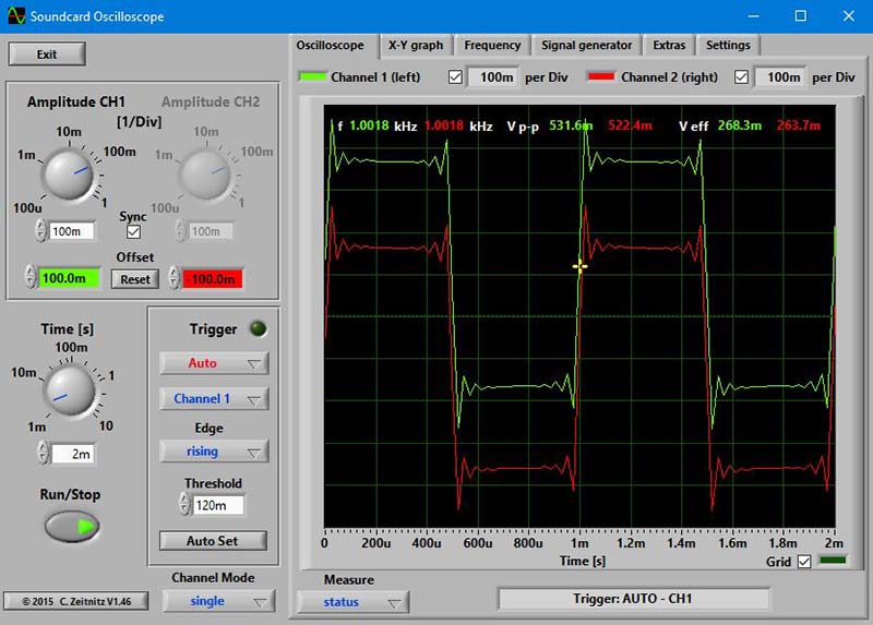
FIGURE 14A. 1 kHz square wave.
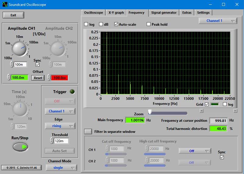
FIGURE 14B. 1 kHz square wave FFT plot of harmonic sine wave amplitudes.
Figure 15A shows a 1 kHz triangle wave and Figure 15B shows the FFT plot of the harmonic sine wave amplitudes.
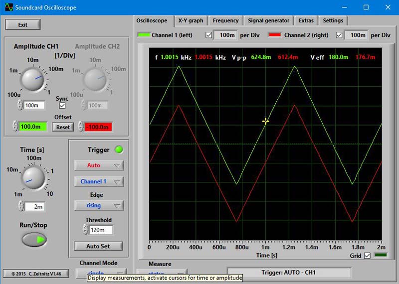
FIGURE 15A. 1 kHz triangle wave.
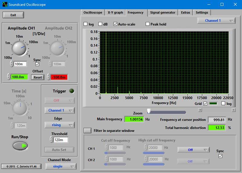
FIGURE 15B. 1 kHz triangle wave FFT plot of harmonic sine wave amplitudes.
Notice the frequencies and amplitudes of the FFT representations. Both waves have odd number multiples of the fundamental frequency. The square wave has much higher harmonic amplitudes and shows THD at 48.43%, whereas the triangle wave has much lower harmonic amplitudes and a THD of 12.53%.
This demonstrates how the more a waveform deviates from a pure sinusoidal shape, the higher the THD and harmonic frequency content. This is why fuzz boxes for guitars drown out the accompanying vocals and other instruments.
I hope you have fun building and using your PC two-channel o-scope. It comes in handy without much cost. NV
Parts List
| QTY |
PART REF |
DESCRIPTION |
| 2 |
R1, R7 |
1 meg resistor 5%, YAGEO, Digi-Key (DK) 1.0MQBK-ND or equiv. |
| 2 |
R13, R14 |
1.0K resistor 5%, YAGEO, DK 1.0KQBK-ND or equiv. |
| 2 |
R15, R16 |
20K resistor 5%, YAGEO, DK 20KQBK-ND or equiv. |
| 1 |
R17 |
470 ohm resistor 5%, YAGEO, DK 470QBK-ND or equiv. |
| 2 |
R2, R8 |
9.00M resistor 1%, metal film, YAGEO, DK 9.00MXBK-ND, or equiv. 9.09M resistor 1%, metal film, YAGEO, DK 9.09MXBK-ND, or Vishay PPCHF9.09MCT-ND or equiv. |
| 2 |
R3, R9 |
900K resistor 1%, metal film, YAGEO, DK 900KXBK-ND or equiv. 909K resistor 1%, metal film, YAGEO, DK 909KXBK-ND or equiv. |
| 2 |
R4, R10 |
90.0K resistor 1%, metal film, YAGEO, or equiv. 90.9K resistor 1%, metal film, YAGEO, DK 90.9KXBK-ND or equiv. |
| 2 |
R5, R11 |
10K resistor 1%, metal film, YAGEO, DK 10.0KXBK-ND or equiv. |
| 2 |
R6, R12 |
100 resistor 1%, metal film, YAGEO, DK 100XBK-ND or equiv. (Only used with 9.09M multiple resistor pairs, jumper with 10M.) |
| 1 |
C1 |
10 µF metalized poly, ±10%, Panasonic ECQ-V1H103JL, DK P4513-ND or equiv. |
| 6 |
C2 |
100 µF metalized poly, ±10%, Panasonic ECQ-V1H104JL, DK P4525-ND or equiv. |
| 2 |
D5, D8 |
LED, GRN (green), Lite-On LTL-4232N or equiv., DK 160-1083-ND. |
| 1 |
S1 |
SPDT slide switch, TE Connectivity, DK 450-1609-ND. |
| 2 |
J1, J2 |
RCA chassis mount phone jack, DK CP-1412-ND. |
| 1 |
J3 |
1/8" (3.5 mm) stereo chassis jack, DK CP1-3533-ND. |
| 1 |
U1 |
MCP6024-I/P quad op-amp or equiv., DK MCP6024-I/P-ND. |
| 1 |
PCB |
Printed circuit board, FR-4, two-sided, 2 oz copper (final), per Gerber files. |
| |
|
Enclosure, SERPAC 032-B, Mouser 635-032-B. |
| |
|
3xAAA battery holder. |
| |
|
BNC female to RCA plug adapter. |
| |
|
Velleman oscilloscope probe SA (PROBE60S) Newark Part #37C2491. |
| |
|
Universal DVM test lead kit, Newark Part # 21-550. |
Downloads
What’s in the zip?
PC two-channel Oscilloscope gerber files
Soundcard oscilloscope program and manual