Or, How to Turn On or Off Two AC Devices Whenever You Want
How's that for a long title? This device really is a universal on-off machine and not just a router restarter. It can be programmed to function in many ways. This project came about because we have a place in Florida to save us from the Michigan winters. While we are not there through the summer months and into the fall, we run the air conditioning to keep the humidity down and prevent "black mold" and other unwanted damage. I installed a smart thermostat that connects to our wireless router so I can check the temperature and humidity in Florida, as well as change settings from my smartphone. The problem I have is that over a period of several months, the router is sure to freeze up and thus need a simple unplug, then plug back in to restart. In the past, this entailed having to call a neighbor and ask them to go over and restart the router.
After noticing a dual relay board on Amazon that would work with an Arduino microcontroller, I came up with the idea of having an RTC (real time clock) connected to an Arduino that would activate a relay that turns off the AC power to the router for a brief period of time.
After a little work on scratch paper, I came up with the circuit shown in the Schematic.
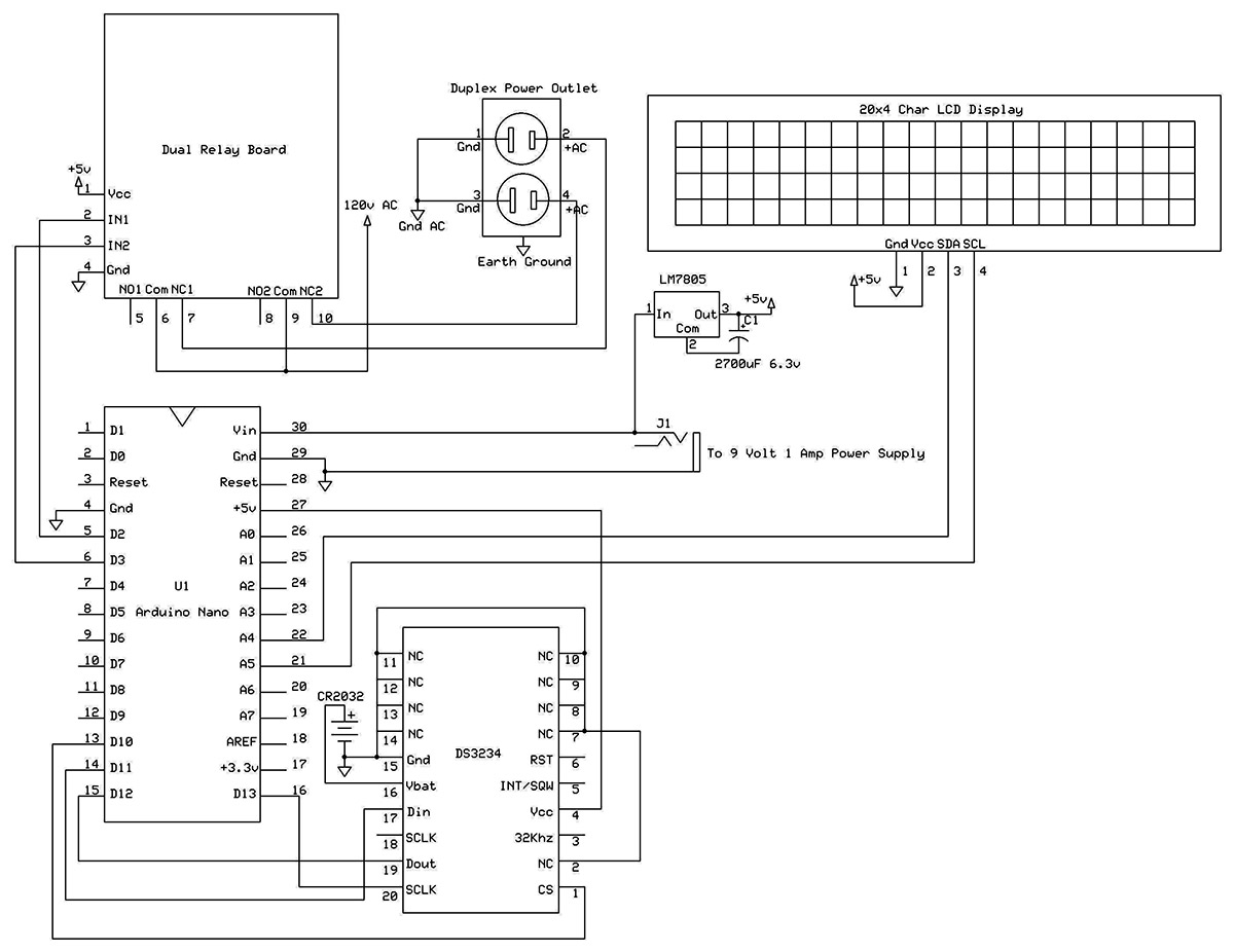
The router restarter circuit.
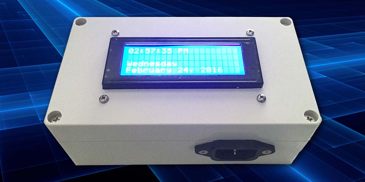
The LCD display was added as an afterthought when I discovered it would fit with everything else in the 158 mm x 90 mm x 60 mm (roughly 6 x 3-1/2 x 2-3/8 inch) plastic box which I had available.

The LCD display mounted in the cover of the box.
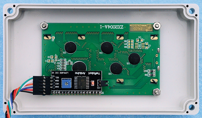
The LCD display mounted in the cover.
I chose an Arduino Nano — perhaps my favorite model — as it has most of the features of the Uno but in a smaller package. In addition, it sometimes works better not to have to build a shield to attach to the Arduino. The Nano, a DS3234 RTC chip, the holder for a CR2032 backup battery for the RTC, an LM7805 five volt regulator, and the two needed four-pin headers are all placed on a breadboard with point-to-point wiring. The DS3234 SMT circuit was mounted on a SchmartBoard SMT to DIP adapter, so it would fit the 0.1 inch pin spacing on the breadboard.
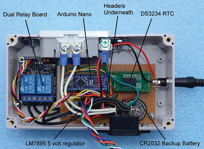
Interior of the box showing parts placement.
For powering the circuitry, a power jack was installed on the plastic box for a nine volt/one amp “wall wart” power supply. The plastic box also mounts a standard duplex 120 volt wall jack to plug in the things needing to be controlled (I chose the type that has a rectangular shape) and a male three-pin panel mounting power inlet socket (like those found on the back of desktop computers).
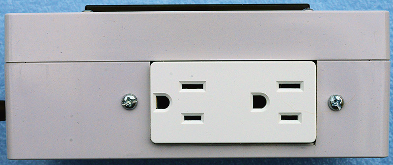
Side view of the duplex 120 volt wall jack.
The power inlet socket takes a standard computer power cord. Along with the breadboard (inside the box) are the dual relay board and a 20-character by four-line LCD display.
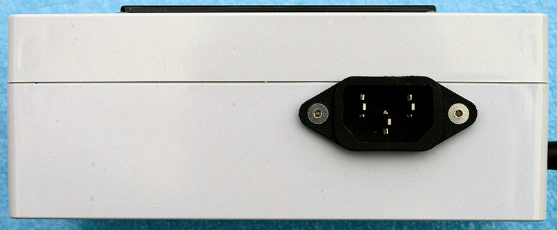
Side view of the three-pin power inlet socket.
The dual relay board’s output contacts are SPDT, so they can be wired up to turn on or turn off a device. The NC (normally closed) contacts were used, but the NO (normally open) contacts could be employed as well to control just about anything that uses 120 volts AC, up to 10 amps.
The software for the device simply turns off the channel 1 relay for one minute at 3:00 a.m. and then turns off the channel 2 relay for one minute at 3:02 a.m. With minor changes in the software and connecting to the NO contacts on the relays, it could be programmed to turn on and off lights or a coffee maker or whatever at different times.
Construction
If you would like to make life easier for yourself, you should consider using a slightly larger box. Everything will fit in a 158 x 90 x 60 mm version, but it is a tight fit. Start by cutting the holes you need to fit the duplex 120 volt wall jack, the three-pin power inlet socket, the round 3.5 mm power jack to mate with your nine volt wall wart, and the rectangular hole and screw holes for the LCD display.
I like to use a drawing program like Visio to create the pattern for the cutouts. For example, with the LCD mounted in the cover of the box, simply draw a rectangle the size of the box cover, a centered rectangle where the LCD will mount, and the four screw holes. When this simple layout is printed to scale, cut out the rectangle the size of the box and tape it to the top of the box. When the rectangular hole is cut and screw holes drilled following the pattern, they will be nicely centered.
You could easily omit the three-pin power inlet socket and just run an AC cord into the box. The LCD display could also be eliminated, but it does provide a nice way to check on the Arduino, the RTC output, and when the relays function.
By cutting down from the top edge of the bottom section of the box for the 120 volt duplex wall jack and the three-pin power inlet socket, it made it quite easy to produce the openings; you are only cutting out three sides of a rectangular opening.
Be sure to leave space to mount the breadboard with its components, and have reasonable clearance for the 120 volt wires that connect power to the relays and the duplex wall jack.
The most time is spent doing the point-to-point wiring on the breadboard. For this, I like to have a printout of the schematic. As I add a connection or wire to the circuit, I use a red marker on the schematic to record what has been finished.
Both the dual relay board and the LCD display have four-pin headers for connections. Use short pre-made four-pin jumper cables to easily connect these to the two four-pin headers created on the breadboard. The CR2032 battery is a must for the RTC. Once programmed, this allows you to disconnect the power and reconnect it later, with the backup battery supplying the power to the RTC and maintaining the time.
Surface-Mount Soldering
The DS3234 integrated circuit only comes in a surface-mount package (an SOIC-20). This means the pins are spaced on .05 inch centers. A SchmartBoard SMT to DIP adapter is a small printed circuit board (PCB) with standard 0.1 inch spaced pins that you solder the SOIC-20 package on. With some care and forethought, it is actually not too difficult to solder the DS3234 to the SchmartBoard by hand.
Here is my method.
- Using the smallest soldering tip you have available, place the smallest amount of solder possible on diagonally opposed corners of the SOIC-20 pads on the SchmartBoard. Using a toothpick (it is also insulated against static) to help place the IC perfectly centered on the pads, press one corner pad down with the soldering iron tip, melting the small solder dot underneath. Do not go on until this first pin is soldered down, which holds the IC in place and ensures that all other pins on the IC are perfectly placed over their pads. If the IC is not perfectly centered over all the pads, melt the solder by placing the tip of the soldering iron on the pin, and reposition it.
- Press the pin down on the diagonally opposite corner, melting the solder under the pad. The IC is now held firmly in place and should be perfectly aligned.
- Apply the smallest amount of solder possible to the top of each pin, without bothering to see if the solder joint is perfect. The smallest amount of solder will do. Often, it is all right to go on to the next pin without adding solder; touching it with the soldering iron tip will deposit a small amount of solder still adhering to the tip.
- With a small amount of solder on each pin top, go back and slowly swipe each pin with the soldering iron tip, moving away from the IC body and melting the solder. If the solder bridges two pins, place the tip between the pins and pull it off with the tip. If this happens, too much solder has been used. If extra solder accumulates on the tip, wipe the tip with a slightly wet paper towel. It is important to keep the tip clean using this method. If the circuit is not working, try going back over the IC pins with the soldering iron tip. Sometimes a pin can look well soldered, but is not, or there is a solder bridge between two pins.
Software
The Arduino software is fairly simple. The main program loop basically reads the clock and then — given the current time — checks to see if a relay needs to be turned on or off.
The SPI library is included for communication with the RTC:
#include <SPI.h>
The Wire library allows use of the I2C two-wire bus:
#include <Wire.h>
The LCD display is one of several different types available and comes with a built-in interface for I2C two-wire communication. This model used the LiquidCrystal_I2C library and compatible settings when initializing the LCD object. Be aware that these settings do vary with different LCDs:
#include <LiquidCrystal_I2C.h>
// Set the LCD I2C address for 20x4 LCD
LiquidCrystal_I2C lcd(0x27, 2, 1, 0, 4, 5, 6, 7, 3, POSITIVE);
There are three functions to simplify the use of the LCD. They are: Display_Time(), Display_Date(), and dateString() — the latter to concatenate the month, day, and year into a single string.
There are also functions to initialize, set, and read the RTC. Here are their prototypes:
// Necessary variables
byte second, minute, hour, ampm, dayOfWeek, dayOfMonth, month, year, f1224;
// Initialize DS3234
void RTC_init_DS3234()
// day(1-31), month(1-12), year(0-99),
// dayofweek(1-7) Sun = 1,
// ampm(0-1) 0 = am, 1 = pm, hour(0-23),
// minute(0-59),
// second(0-59), 12/24 hr, (0-1) 0 = 24 hr.,
1 = 12 hr.
// Set Time and Date info
void SetTimeDate_DS3234(byte d, byte mo, byte y, byte dw, byte ampm, byte h, byte mi, byte s, byte f1224)
// Read Time and Date info
void ReadTimeDate_DS3234(byte *second, byte *minute, byte *hour, byte *ampm, byte *dayOfWeek, byte *dayOfMonth, byte *month, byte *year)
The relays are controlled by simply connecting the input pins on the relay board to digital pins on the Nano, and setting the digital pin output to HIGH to activate the relay or LOW to deactivate. These three functions handle the operation of the relays:
// Set Start Time
// Channel number 1-2, hour, minute, AM or PM
void setStartTime(byte chan, byte h, byte m, byte apm)
// Set End Time
void setEndTime(byte chan, byte h, byte m, byte apm)
// check Time
void checkTime()
setStartTime sets the channel number (the relay to be used) and the time to activate it. setEndTime sets the channel number and the time to deactivate it. In all cases, only the hour and minutes are used. checkTime checks the time against set times for activating or deactivating the relays and acts if necessary.
Included in the setup block of the Arduino program are the following:
// Set our times on the two channels
setStartTime(CHAN1, 3, 0, AM);
setEndTime(CHAN1, 3, 1, AM);
setStartTime(CHAN2, 3, 2, AM);
setEndTime(CHAN2, 3, 3, AM);
The cable modem is powered by channel 1, which will be turned off at 3:00 a.m. and turned back on one minute later. The router is powered by channel 2 and is connected to the cable modem. It is turned off at 3:02 a.m. and turned on one minute later.
The complete program can be found below in the downloads
.When programming the Arduino Nano, here's an important point not to miss. Program the Nano with the SetTimeDate_DS3234 function in the setup block of the program. The function includes the current time and date at your location. This will set the real time clock going in the DS3234, and with the installed CR2032 backup battery, the clock will continue to run when power is removed.
Next, comment out the line with the SetTimeDate_DS3234 function, then program the Nano again without it. Now if you remove power, the DS3234 will continue to run. When you power-up the Arduino Nano without the SetTimeDate_ DS3234 function, it will not overwrite the clock's current time. Notice also that the five volt power for the DS3234 comes from the five volt output of the Nano. This allows you to plug in your USB cord to program the Nano, plus the DS3234 will be powered as well. This is convenient for debugging as the five volt LM7805 regulator does not need to be powered.
Improvements
What this project doesn’t have is an easy way to change the start and end times for the relays. For my project, this wasn’t a problem. For those who need to make changes, the only way is to make changes in the program and then upload the new program to the Arduino Nano.
Changes could be done with the TSOP38238 infrared receiver available from Adafruit and also their mini remote control. There would also need to be some extensive software additions to receive the various signals to change the start and end times, but this is certainly a possibility. NV
Parts List
- Arduino Nano
- Arduino Compatible Dual Relay Board
- 20-Character x Four-Line LCD Display with I2C Interface
- DS3234 Real Time Clock, mounted on SchmartBoard SMT to DIP Adapter
- CR2032 Battery and Holder
- LM7805 Five Volt Regulator with Mini Heatsink
- 2700 µF Electrolytic Capacitor, 6.3 volt Rating
- Duplex 120 volt Wall Jack
- Three-Pin Power Inlet Socket and Mating Computer Power Cord
- 3.5 mm Power Jack, Compatible with nine volt/one amp Wall Wart Power Supply
- 158 mm x 90 mm x 60 mm Plastic Case or Larger
- Breadboard with 0.1 inch Pin Spacing, Cut to Size
- Miscellaneous Hookup Wire, Spade Connectors, Header Pins, Six inch Four-pin Header Jumper Cables, Screws, Nuts
Downloads
Arduino Source Code For The Router Restarter