For the past few years, I have had as part of my backyard Christmas light display a 'tree' made up of eight LED light strings strung in a pyramidal fashion to a central metal pole. (Refer to “The Tree” sidebar.) At night, it was a nice display that worked well, but as a static display it grew to be boring. I needed to add some action using a light controller.
There are a number of commercially-available Christmas light controllers that can be programmed to act in conjunction with music, control many channels of lights with various effects, and handle high current loads — all with price tags that match the capabilities. Other options are simple, but repeat the same pattern and quite often are integrated within the light string itself.
For me, I didn’t want to have to synchronize with music; I didn't want the same patterns night after night or something that required operator interaction. I just wanted a simple controller that I could plug in a few sets of lights to and apply power.
The project in this article is low cost and simple to build, while providing several different light patterns in random order and speeds. Each time the circuit is powered up, the pattern order is different, only repeating after 65,535 power cycles. Several of the patterns are random themselves, and the speed of light change is randomly selected. Should you want to, it's easy enough to change the speed and modify the patterns.
Circuit Description
The circuit is built around the PIC16F690 and an eight-channel solid-state relay (SSR) board that is readily available. The circuit (as shown in Figure 1) is simple enough to build on a perf board.
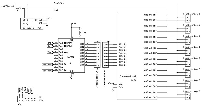
FIGURE 1. Eight-channel light controller schematic.
Configuring the board so it interfaces to the SSR board was also fairly easy. If you use a different relay board, then you may have to modify it.
Though I selected the PIC16F690 for this project, there are many other eight-bit microcontrollers that could be used. I chose the 16F690 because its port C is eight bits wide, making it very easy to address as we will see later in the description of the software; there are enough other I/O pins to leave ISP and UART available for use, and I already had several on hand and was familiar with them.
Though the UART is not used in the final design, the serial interface was utilized extensively during prototyping, and may come in handy should you want to change patterns. Port C is interfaced directly to the inputs of the SSR board. In software, you can choose whether active high or active low is used to select a channel. I use the PIC16F690’s internal oscillator since timing or high speed is not critical.
The SSR board shown in Figure 2 is reasonably priced and less than the cost to buy the components to build it — let alone the cost to fabricate the printed circuit board (PCB).
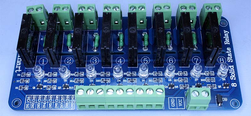
FIGURE 2. View of the solid-state relay (SSR) board.
Each channel is optically isolated, fused, has an LED indicator that is useful when troubleshooting, and is built for operation at a household mains potential. With the SSR board operating at five volts and inputs spaced at 0.2”, the interface to the microcontroller was quite easy. (Refer to the sidebar).
The maximum current for each channel is two amps, but with LED light strings you will be pushing much less current through each channel. In fact, during initial testing, I was concerned that one LED light string would not present a large enough load for the triac to fully turn on and off; fortunately, the switching worked well. I recommend using LED light strings because not only is their power consumption low, the colors that LEDs produce are more brilliant than incandescent lights shining through tinted glass.
Why use solid-state relays instead of electromechanical relays?
The easy answer is solid-state relays (SSR) don’t make any noise. Plus, they are much more reliable than electromechanical (EM) relays. In fact, an EM relay would likely not survive a holiday season of operation! The lifetime for EM relays is specified in the number of contacts made — about 100k contacts for a typical EM relay. Because there are no moving parts, the lifetime for an SSR is specified in hours of operation; minimally 100k hours, though many SSRs have lifetimes in excess of one million hours.
Let’s assume that the light controller is used between Thanksgiving and New Year’s Day (35 days) for six hours per day. If we assume a conservative one contact per second, the number of contacts made would be 35 days * 6 hours/day * 3600 seconds/hour = 756k contacts. This is well over the predicted lifetime of 100k contacts. Meanwhile, the SSR is operating for 210 hours which is a small fraction of the 100k hours lifetime.
Since we are switching very low currents with the EM relay, in the case of LED light strings, we can generously increase its lifetime to one million contacts. Even then, the story is still not too promising. Under those conditions, an individual EM relay’s probability of surviving the holiday season is only 47%, while for the SSR it is 99.8%. For eight relays, the probabilities of survival for the system using EM relays or SSRs are 0.24% and 98.4%, respectively, using the very low current assumption.
Software
The software was written in C using Microchip’s MLAB IDE (integrated development environment) and the HiTech PIC lite C compiler. The source code is available in the downloads. Essentially, the program uses the random number generator in C, rand(), to provide an ever-changing light show by randomly choosing from 15 different patterns and two speeds. The program is simple: First, the pattern and speed are chosen, then the pattern is executed a set number of times. It then loops back to pick a new pattern and speed, and executes the new pattern.
Generating Random Numbers in C
In C, rand() uses an algorithm to provide a series of pseudo random integers between 0 and RAND_MAX (a large number defined by the library). The algorithm is started by rand() and uses a seed generated by another function, srand(int s). By using different values of ‘s’ in srand(), the series of integers generated by rand() are different. Likewise, using the same values of ‘s’ in srand() will produce the same series of integers.
You can see this for yourself by writing a simple program that prints out the sequence of integers produced by rand(). In this project, we ensure that the generated series is different each time the controller is powered up by adding one to the previously used seed which was stored in the microcontroller’s EEPROM. The new seed is then stored in EEPROM so it can be incremented at the next power-up.
A quick Web search on rand() will bring up several discussions on the ‘randomness’ of it — especially when restricted in a small range as used in this program. If you are generating random numbers for encryption, unique identifications, or other security sensitive applications, this is a concern. In this application, by changing the seed each time the light controller is powered up, the randomness is good enough.
As noted earlier, rand() will generate a very wide range of integers from 0 to RAND_MAX. What if you only want a smaller range of integers (for example, 0 to 7) that is used extensively in this project? The modulus — the remainder after division — is used to restrict the range as shown in this code for the RandomNumber function:
char RandomNumber(unsigned char range)
{
n = rand();
char rnmbr = n % range;
return rnmbr;
}
Here, the variable ‘range’ is (n+1) which restricts the generated random integers to between 0 and n inclusive. For example, for range = 8, the returned integer will always be between 0 and 7 since you cannot have a remainder greater than 7 when you divide by 8.
For example, if the remainder is 8, then the number is evenly divided by 8 giving the modulus of 0. In the code, we start each cycle by choosing between two speeds by using RandomNumber(2) returning either a 0 or 1, and then choosing a pattern (or mode) by using RandomNumber(15) and returning an integer between 0 and 14.
You may notice there is a test to see if the pattern (mode) would repeat. I found in my early prototypes that patterns and the actual display would repeat periodically. This occurs because we are restricting the range of our random number generator. Even though the random number generator produces two different integers, they will appear to repeat if they have the same remainder.
I found that generating another random integer will cut the repeats so they are infrequent and not obvious to the observer. I used the same test in several of the patterns, too.
Using Port C to Drive SSR Board Channels
Another one of the reasons I chose the PIC16F690 was that port C is eight bits wide, so it is simple to write a value to port C. Writing to the PORTC register allows you to directly write the desired state for each output. Bit 0 of PORTC is the value for C0; bit 1 is the value for C1 — all the way to C7.
For example, PORTC = 0b10101010 will cause all even outputs to be low and all odd outputs to be high. Once the pattern is selected, the corresponding routine is executed to turn on the desired channels of the SSR board.
Let’s take a look at the function that drives the corresponding port C outputs of the microcontroller:
char PortCDriver(char selected, char nchan, char onchan, char logic)
{
space = 0;
if (nchan == 2){space = 4;}
if (nchan == 3){space = 3;}
char port=0xFF&0x01<<selected |
0xFF&0x01<<((selected+space)%8) |
0xFF&0x01<<((selected+space*2)%8);
char flip=onchan^logic;
//determine if outputs need to be toggled
if (flip){port=port^0xFF;}
PORTC=port;
return port;
}
There are a number of parameters for this function: selected is the active channel for the pattern; nchan is the total number of channels to be active (1, 2, or 3); onchan sets whether the active channels are lit or dark; logic is positive or negative logic.
With this function, we can take the channel that has been selected by the pattern’s routine and add an additional one or two channels equally spaced around the perimeter of the tree. This will give an appearance of channels dancing around the tree. Notice that the spacing is added to the selected channel and modulus 8 is used to keep the result between 0 and 7.
For example, if the pattern calls for three active channels and the selected channel is 2, the other two active channels will be 5 and 0 (i.e., (2+2*3)%8 =8%8=0). These channels are ORed together and written into PORTC after it is determined if the bits need to be toggled — which depends on whether the active channels are lit or dark and which logic is required. By understanding how each parameter affects the operation of this function, you will be able to build your own set of patterns.
Examining a Few Patterns
To get some insight on how the display patterns are generated, let’s take a look at two patterns: one that is random, and one that is sequential. In operation, the particular pattern and the speed is chosen using random number generators at the beginning of each while(1) cycle.
If pattern (i.e., mode) 4 is selected, then the following code — using yet another random number generator — is executed. This pattern specifically blanks the active channel, as well as an additional channel spaced by four channels; the other six channels will be lit. As you will see, this pattern gives the appearance of two dark strings directly opposite each other dancing around the tree:
// Blanks only channel corresponding to generated number plus one spaced channel
// For two enabled channels the spacing is four, for three enabled channels the spacing is three
if (mode==4)
{
for (i=1; i<=reps; i++)
{
char eight = RandomNumber(8);
if(eight%4==oldeight%4)
{
eight = RandomNumber(8);
} //end if
oldeight=eight;
PortCDriver(eight,2,0,portclogic);
pause(dd);
} // end for
} // end if
The pattern is executed 32 times as defined by the variable reps. During each execution, a random integer between 0 and 7 is generated and is used to select the active channel. Once again, we test for repeats as discussed earlier, but this time we use modulus 4 instead of modulus 8. This is because we will be activating two channels, with the second channel spaced four channels from the selected channel.
For example, selecting channel 0 looks the same as if channel 4 was selected. Once the active channel has been selected, the PortCDriver() function is used to drive the SSR board. Here, we designate the selected channel with the variable eight; there are two active channels, the active channels are blanked, and the port logic is defined by the portclogic variable. Pause(dd) freezes the pattern for either 250 milliseconds (dd = 0) or 500 milliseconds (dd = 1), setting the speed of the display.
In this next example, two opposite channels are active and will be lit while the other six sets of light strings will be dark. The pattern will appear to rotate around the tree four times. This pattern is executed when pattern 14 is selected:
// Enables only one channel and spaced channel
// decreasing rotation
if (mode==14)
{
for (i=reps; i>=1; i—)
{
char eight = i%8;
PortCDriver(eight,2,1,portclogic);
pause(dd);
} // end for
} // end if
Similar to the prior example, this pattern is executed 32 times, but in this case the selected channel is not random, but rather the modulus 8 of the rep count as it decreases from 32 to 1. Since I chose 32 for the number of repetitions of patterns, the cycle will repeat four times.
Again, the function PortCDriver() is used to drive the SSR board with the selected channel designated by the variable eight; the number of active channels is two, the active channels will be lit (i.e. enabled), and the port logic is defined by portclogic.
Construction
This project involves switching the mains voltage and currents that can be dangerous to human life. Your safety and the safety of others should be the first priority as you build this project. If you are not experienced or don’t feel confident in working with mains voltages and currents, get help from someone who is experienced in dealing with household voltages and currents.
Enclosure
Since my controller is outside at the base of the tree, a top concern for me was to keep water and prying fingers from entering the enclosure. To do this, I minimized the number of holes that could let water in by eliminating any adjustments or other controls. My controller — and the rest of my holiday lighting — is powered by an outlet connected to my home automation system, so I left out the power switch.
The only holes needed are for the power in and each of the switched channels. In my case, I used a plastic food storage container that is waterproof. It worked well for me since it is sealed against the elements and is electrically isolated. It is not secure enough to prevent access while it is powered up, however. If contact with the box is possible, then you should use a waterproof enclosure that is secured with fasteners or move the controller into a secured location.
To bring power to the controller and deliver switched power from each channel to the light strings, I used polarized power extension cords with the unused end cut off. These cords have polarized plugs and outlets with one large blade (neutral) and one small blade (hot).
During construction, keep proper polarization so that you are fusing and switching the hot side, while neutral is only used as the return. After cutting off one end of the extension cord, you can use an ohmmeter to identify which lead is hot. This is the side that will be switched by the SSR board.
To keep the enclosure waterproof, I had to make sure each power cord entry was sealed. I used a grommet to protect the cord from the plastic edge of the hole it passed through. Since the cords that I used were flat rather than round, fitting the grommet was more challenging than simply drilling a round hole. I used two smaller adjacent holes to form an elongated hole. After clipping out the plastic between the two drilled holes, an elongated hole just larger than the cord was produced.
The cord is pulled through the hole after fitting the grommet. Threading the cord through the grommet should be tight; I practiced this on a scrap piece of plastic first to get the right size and fit. In addition, I used a plastic zip tie around the cord on each side of the hole to keep the cord from moving, then some silicone as a final water tight seal.
Microcontroller Board
Since the circuit is simple, I used a perf board for the microcontroller related circuitry. The layout of the board was arranged so it would easily interface to the SSR board. The input terminals of the SSR board are spaced 0.2” for all eight channels and ground. I used 17 positions of a right angle male 0.1” header; keeping the outer pins, I removed every other pin so nine 0.2” spaced pins were left.
I soldered the shorter pins on the edge row of the perf board, with the longer pins extending out from the board so they could mate with the SSR board. This takes care of the connections for channels 1 through 8 and the ground connection.
Next, wire the header pins to the appropriate pins on the microcontroller. The completed microcontroller board is shown mated to the SSR board in Figure 3.
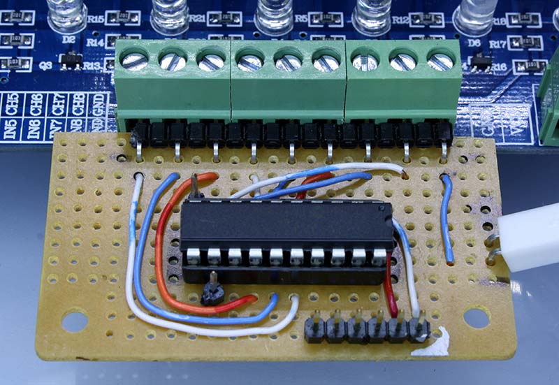
FIGURE 3. Microcontroller board mated to the SSR board.
Looking at the microcontroller board in Figure 4, you will notice pins for ICSP, Rx, and Tx for future use or for modifying the program; these pins are optional.
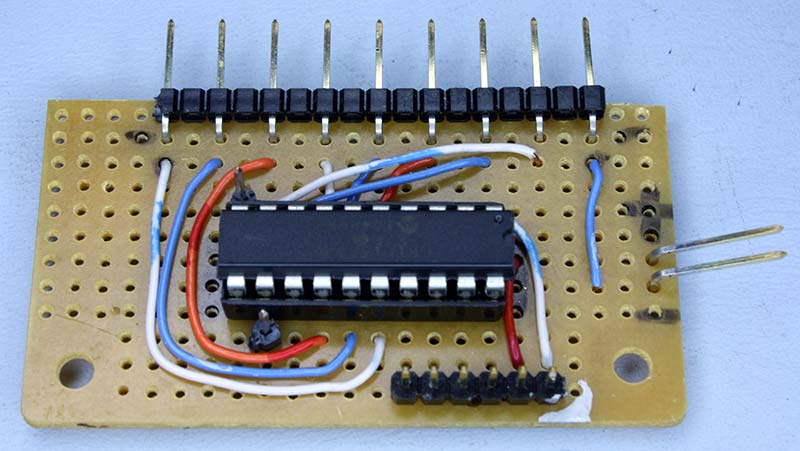
FIGURE 4. Microcontroller circuitry built on a perf board.
I used a socket for the microcontroller with the decoupling capacitor, C1, mounted between the two rows of the socket beneath the socketed microcontroller. This allows the capacitor to be very close to the Vcc and ground leads while taking up less space. The only other connection is a male two-pin header for power, fed from a five volt wall wart supply.
SSR Board
Using the prebuilt SSR board makes wiring the high voltage mains circuitry easier and safer. Even so, precautions must be taken to make sure polarity is maintained; there is no exposed high voltage and use of wire size that can handle the current that will be passing through it.
As shown in Figure 5, leads are dressed and color-coded so polarity is maintained; the hot side of the AC should be switched by the SSR board while neutral is used for return (or common).
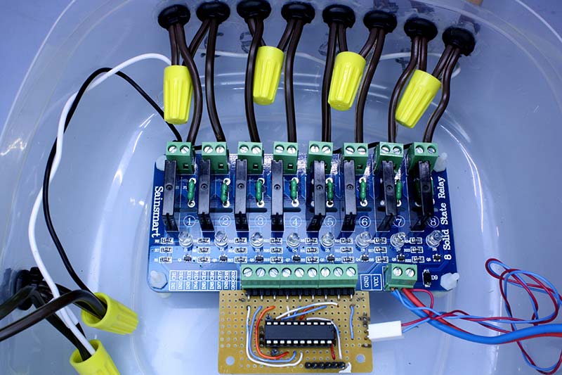
FIGURE 5. Close-up view of the AC wiring
Traditionally, hot is connected with black insulated wire and neutral with white insulated wire as used here. Be sure that the wire insulation is rated for household voltage.
Each channel of the SSR board is rated for two amps, so you should limit current draw to less than that. In my case, I was driving a single string of LED lights that draws very little current. Depending on your current draw, make sure your wire size is sufficient; for two amps, #18 wire will be adequate. For the common hot and neutral wires feeding the SSR board and lights, the current draw will be eight times the individual channel current draw.
In my case, the total current draw is still low, but could be significant in your configuration. If each channel is passing close to its two amp limit, your common feeds need to be at least #14 wire. If you don’t have experience in determining current draw and sizing wires appropriately, get help from someone who knows how to do this.
Connect the hot side of the outlets for your lights to the switched side of each channel on the SSR board. The neutral side is shared among all channels; use wire nuts to connect the neutrals together. Don’t do this with just one wire nut. Connect two channels together to the common neutral with one wire nut and daisy-chain to the adjacent channels. This not only gives a neater layout but also puts less stress on the connections.
Plastic screws, nuts, and standoffs are used to support the SSR board. The SSR board and the connected perf board float in the case, held in place by the connecting wires. This was done to eliminate additional holes that would be used to mount to the case, reducing possible compromise of the weather seal.
The power to the SSR board is also supplied by the five volt wall wart used to power the microcontroller board; connect power to the Vcc and GND terminals on the SSR board. The completed assembly is shown in Figure 6.
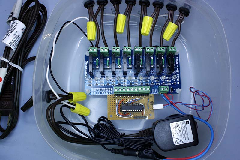
FIGURE 6. Completed assembly before installing the cover.
Startup and Troubleshooting
After building the microcontroller board, it is easy to check for operation. Connect the microcontroller board to the SSR board and supply power from the wall wart to both boards; no need to hook up the outlets or light strings just yet. The SSR board called out for this project has an LED on each channel that lights when the channel is selected.
When powered up, you should see a series of changing patterns of lit LEDs on the SSR board. If not, make sure that you have properly connected the microcontroller board, and check your perf board wiring. Once this test has passed, go ahead and place the boards into the enclosure and attach the power and switched outlets for the light strings.
There are no adjustments needed — just supply power and the controller will run on its own.
Make sure the voltage to the SSR board is close to five volts. I found that if the voltage is low, the selected channel LED will still light but the solid-state relay may not turn on. This confounded me for a while during prototyping until I found that my voltage had dipped below five volts.
Modifications You Can Make
There are modifications to the controller you can make including patterns, speed, and the number of channels. You can easily add or modify the patterns that the controller generates.
When I was prototyping the circuit, I drove the LEDs directly with the appropriate series resistor from the PIC16F690. I arranged the LEDs in approximately the same pattern as the final display which, in my case, was a circle. This gave me an idea what the pattern would look like, which I found quite useful.
If you add or delete patterns (modes), be sure to change the modulus where the mode is selected. You can change the speed of the pattern by modifying the delay in the pause() function, and the number of times the display is stepped by modifying the variable reps.
Modifying the number of channels is more complicated, but can be done by experienced builders. The PortCDriver() function may need to be modified, and the range of random numbers generated in patterns would have to be modified, as well as the modulus used in other patterns.
If you want to use more than eight channels, then other ports of the microcontroller will have to be used, as well as additional SSR boards.
I hope you will enjoy building this project. It made a big difference in my holiday display. It will do the same for you. NV
The Tree
The tree that is used with this controller has a center pole from which eight LED light strings are hung, flaring out to form a tree-like structure. Each LED light string makes two legs, giving a total of 16 legs.
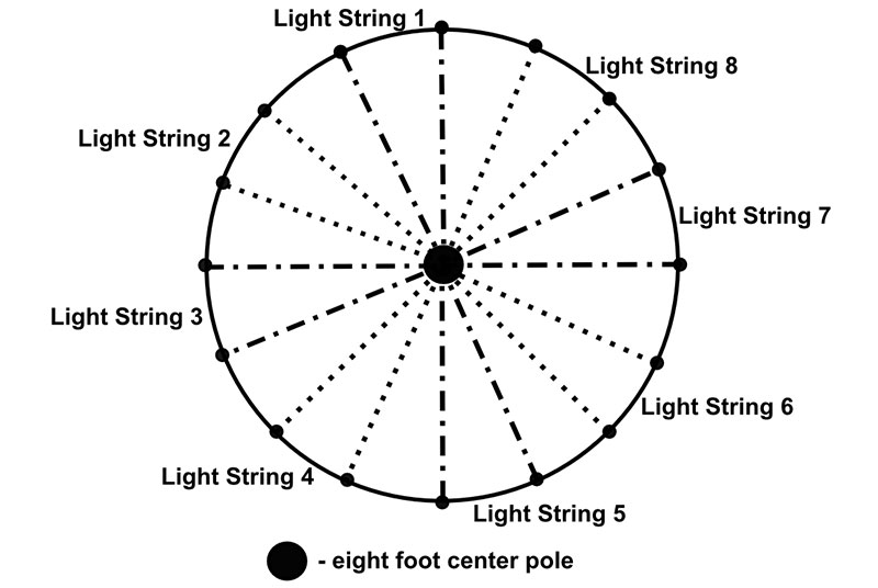
The tree as viewed from the top. Eight sets of LED lights result in 16 legs.
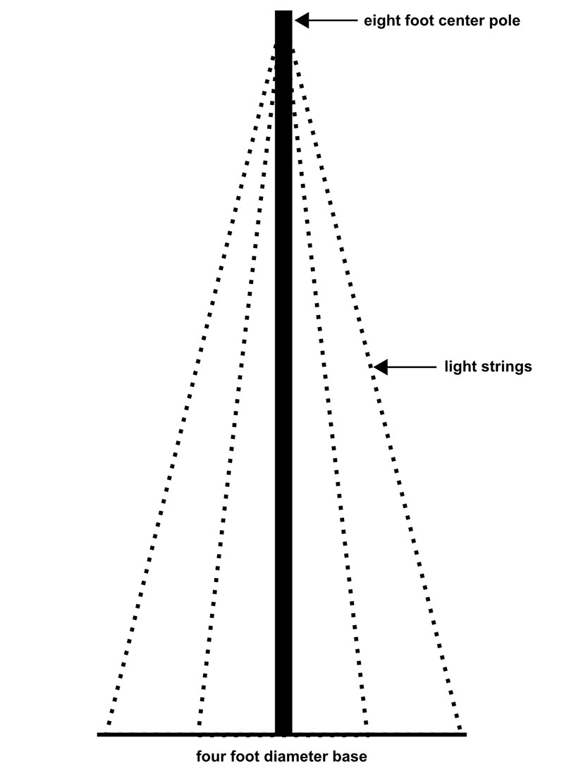
A pleasing proportion is for the height of the center pole to be twice the diameter of the base of the tree. I used an eight foot pole with a base diameter of four feet.
 \
\
Side view. The legs are the LED light strings meeting at the top of an 8' metal pole.
The middle of each light string is at the top of the pole, with the ends at the base. Each light string is plugged into the controller sequentially. The controller sits on the base of the tree.
| Item |
Description |
Part# |
Notes |
| BRD1 |
Eight-channel 5V SSR |
101-70-111 |
SainSmart |
| C1 |
0.1 µF |
|
|
| F1 |
Fuse and Fuse Holder |
|
Sized per total current demand |
| J1a |
17-pin .1" Male Right Angle Header |
|
|
| J2 |
Six-pin .1" Male Header |
|
|
| PS1 |
Five volt >= 200 mA wall wart |
|
|
| U1 |
Eight-bit PIC Microcontroller |
PIC16F690-I/P |
Newark |
| Misc |
Polarized Extension Cords |
|
Hardware store |
| Misc |
Wire Nuts |
|
Hardware store |
| Misc |
Zip Ties |
|
Hardware store |
| Misc |
Silicone |
|
Hardware store |