 This is not only a great teaching project for soldering surface-mount components, it is also perfect for the holidays and very inexpensive. Now, you can help cultivate interest in a budding student getting started in electronics AND take care of some gift giving in one fell swoop.
There are two projects in this article. The first utilizes surface-mount parts with a microprocessor. It has 16 different colored LEDs that flash randomly, blink, have patterns that run up and down and down and up, and flash different colors. It equates to about one minute of programming. The other project uses through-hole components. The new rainbow LEDs used here change colors and blink. This is about a three minute project. (My wife actually prefers this style.) Both versions use a small hearing aid battery. There’s a video available in the NV Webstore if you’d like to see these two different types in action.
This project helps to teach hand surface-mounting and has assembly files that can be changed to make your own patterns. Normally with my projects, I include programming pads so you can change the programming on the board. This one does not, however. The low impedance on the programming pathways prevents this, plus there’s not much space.
The board files were generated using ExpressPCB and their free software (www.expresspcb.com). These files along with hex and assembly files for the microprocessor are available at the article link. If you don’t want to worry about programming, there is a complete kit available from the NV Webstore.
 |
| Figure 1 |
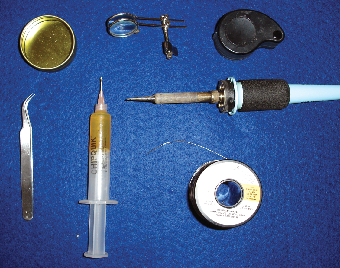
Okay ... let’s get started by first discussing some helpful tools and tricks to make your construction faster, safer, and easier.
You won’t really need much in tools. Curved forceps (check out Mouser 578-EROP7SA for $3.90), a small tipped soldering tip (I use a Weller PTS8 1/64” long), “Tacky Flux” (Chip Quik SMD 290), small solder wire (I use Kester 0.60 mm), and solder wick .030 (Digi-Key 60-1-5-ND). If you’re like me, a lit magnifying lens, loupe, or head magnifier will also be of use. Check out Figure 1.
You won’t need a reflow oven for this project.
SIMPLE TOOLS THAT HELP
 |
| Figure 2A |
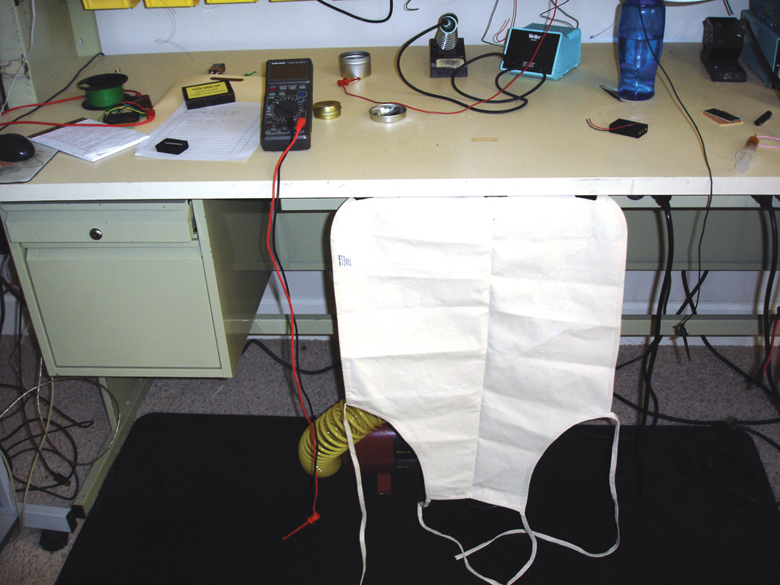
USE AN APRON
Although you may look weird, it is well worth using an apron. Find a white or neutral color with no pockets. Do not use an apron with a busy design in case a component decides to fall on you (or the floor). Pick up some Velcro© and sew or glue it on the top side of the apron in the two corners and also in the center of the bottom edge (I usually attach three squares of Velcro.) Refer to Figure 2A.
Stretch the apron out, and put three 4” strips under the edge of the table where the Velcro strips are. This will allow flexibility when using the apron (Figure 2B).
 |
| Figure 2B |
Now, if something decides to fly off your work area, it will be easier to retrieve it.
MAKE UP NEEDLE PROBES
Nothing is more frustrating than to find a surface-mount resistor or capacitor that has gotten mixed up and has no markings. Make up a set of probes using two 1.5” needles. Solder the needles to a small length of flexible wire and tin the other end. (This is becoming more of a sewing article than an electronics one!)
When you find a strip of components and don’t know what they are, you can pierce the package and measure. This also makes it easier to identify the anode and cathode of LEDs or diodes if the markings have rubbed off.
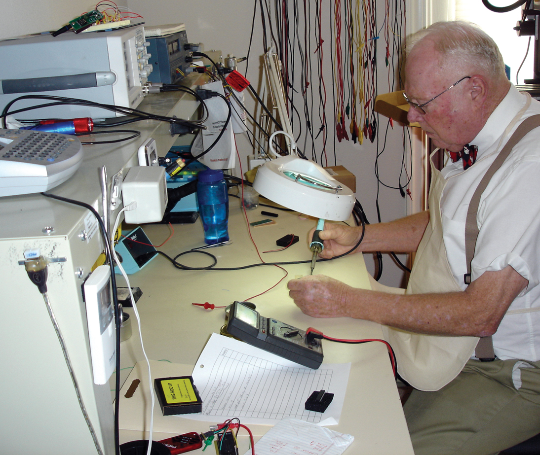
HOW TO SURFACE-MOUNT BY HAND
One of the tricks to surface-mounting is to have a very steady hand and a board that will not move. I use double-sided tape. This will allow your forearms to rest on the work bench. It is also great for sticking battery supplies to another chassis.
 |
| Figure 3 |
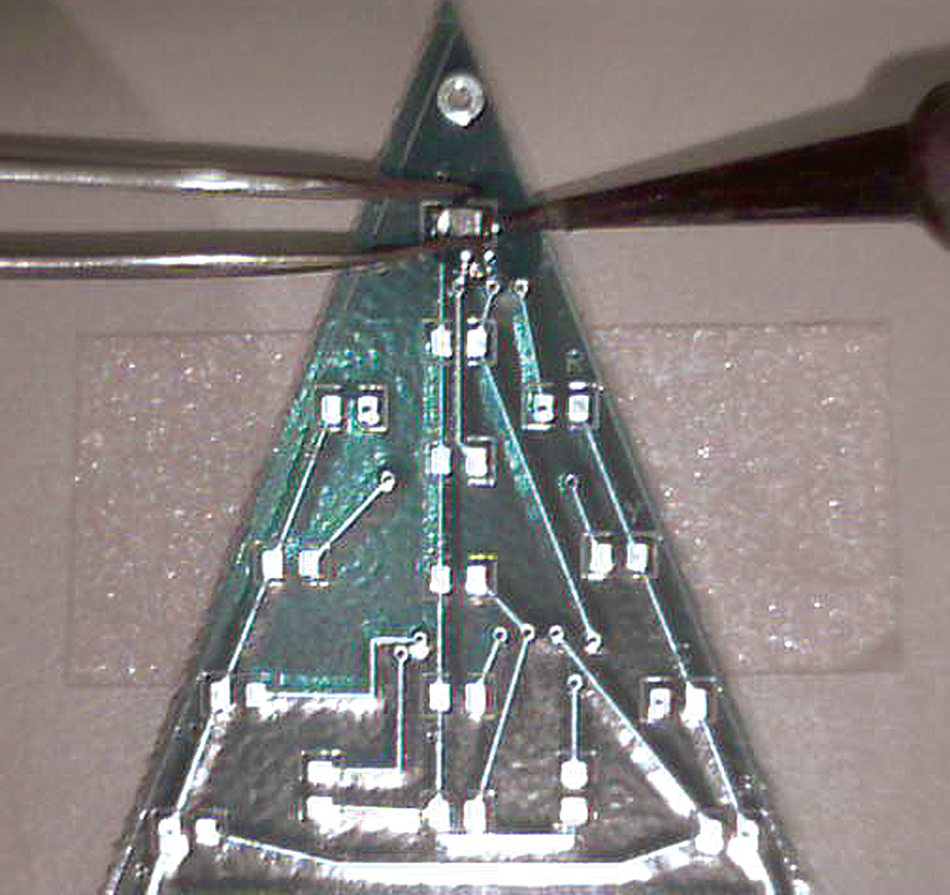
Place the double-sided tape to the bench where your arms will feel comfortable. Have it extend farther than the board. Peel off the upper side of the tape and stick the earring board to it. This makes it easy if a part is upside down or the marking is on the wrong side. Just touch the part to the tape and (it will stick) roll it.
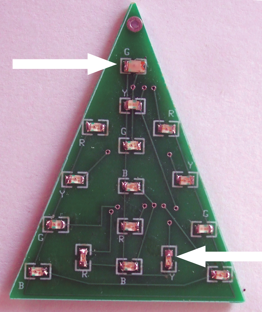
Let’s try this with a green LED. Find the pads that have a “G” and add a dab of tacky flux to both pads. Find a green colored LED, locate its cathode (normally has a marking on top), and place the cathode next to the G marking. On the Christmas tree board, the cathode is marked with the color of the LED. Solder the components so they are horizontal and not vertical. (If they’re vertical and you are right-handed, your tweezers “hand” will be in your stomach.) Watch the LED cathodes on the right side as they are opposite of those on the left side and center. (Refer to Figure 3.) Remember to rotate the board, not the components.
The first thing I do is see if the board pad has enough solder to tack the part. Most boards are tinned and many components are also. Put a small dab of tacky flux onto the pad and place the part onto it, holding it with the curved forceps. Touch the soldering tip to the pad and component. If it sticks, you are home free. If not, add a small amount of solder to the pad and try again. Once tacked, use sparse amounts of solder that touch both the pad and the component’s connector. If you put too much solder, you’ll create a solder bridge! Just take the clean end of a piece of solder wick and touch it to the part. Ta-Da ... it’s cured!
Some quick rules of thumb: 605s are very difficult to hand solder; 805s are fairly easy to hand solder; and 1206s are a piece of cake.
THE “DAUNTING” CHIP
Actually, chips are really easy. Place tacky flux on each pad and place the chip onto the pads. Make sure pin 1 is in its correct position! Remember: Rotate the board, not the components.
Tack pin 1 and the pin in the upper right-hand corner. Solder the rest of the pins. Some people flood all the pins by dragging the solder across them, then remove the solder bridges using solder wick. This is up to you, of course, but if you’re a novice, I would practice soldering each pin individually.
LET’S BUILD EARRINGS
Now that I’ve made you an expert in hand soldering surface-mounts, let’s complete the board.
 |
| Figure 4 |
To keep track of all the colored LEDs, I would mount all the greens at the same time, following with the other colors. Dump all the greens into a canister (or receptacle of your choice).
Solder all the green LEDs, then the red, yellow, and blue ones to the top of the board. Remember the cathode goes to the color marking. Only LEDs will be on top of the board. Note: For comparison of sizes, I soldered a 1206 LED for the top and two 605s on the vertical LEDs just to show you can actually hand solder 605s. The rest are 805s (Figure 4).
The reason we did the top first is that it makes a flat surface when turned over.
So, turn the board over and place the top of it to the double-sided tape. Solder the two transistors, U2 and U3. Solder the two 10K (R1-R2) resistors just above the transistors. They do not have any polarity.
 |
| Figure 5 |
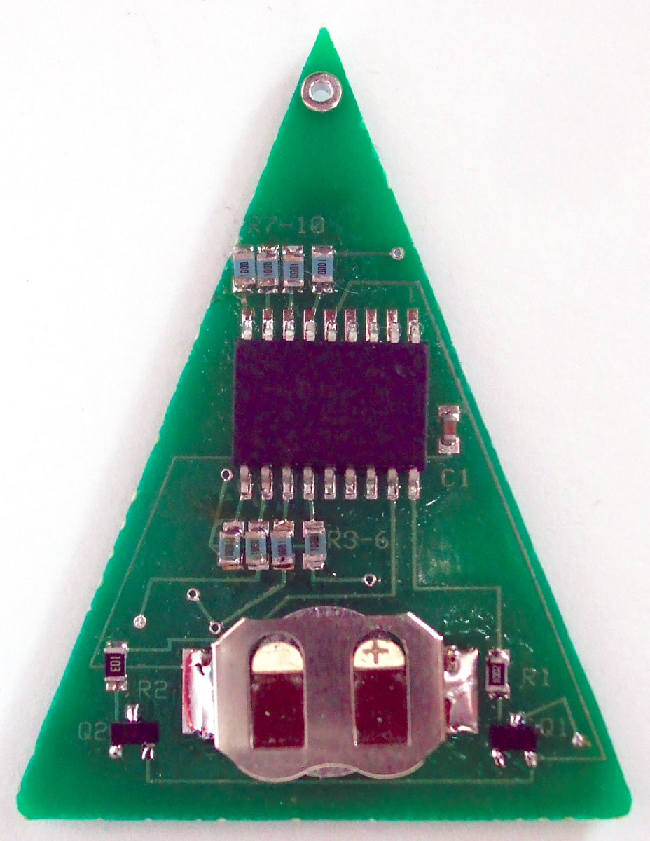
Solder the remaining 100 ohm transistors (R3- R10) to their pads. Solder C1. It has no polarity, either. Solder IC1, noting where pin 1 is. Solder the battery clip (Figure 5).
Put in the CR1225 battery, and the earring should start to flash. The battery should power the earrings at least eight hours. I ran a one minute statistical analysis of both units, and the average draw is about 2-3 milliamps.
THE CIRCUIT
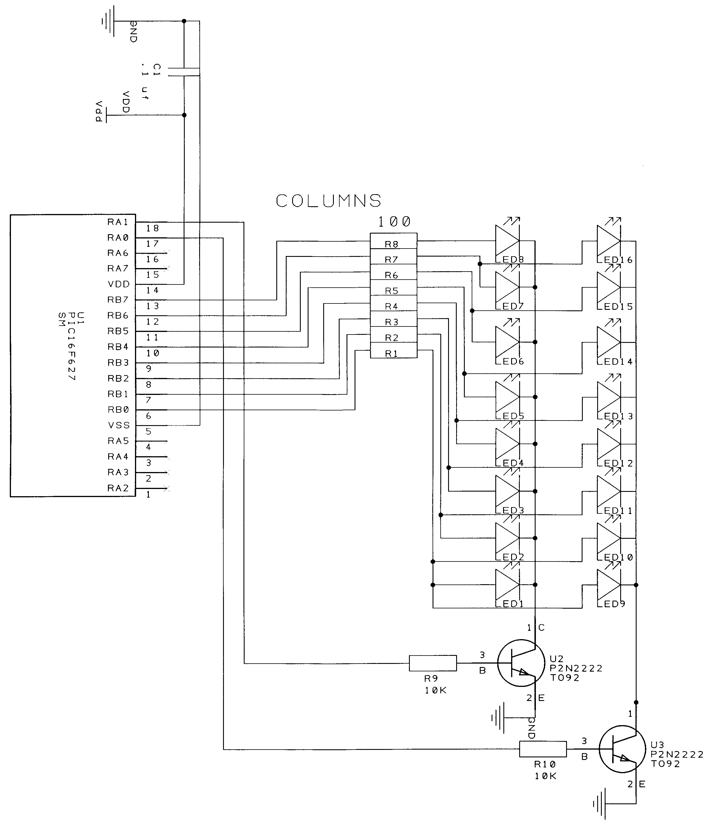
The Microchip PIC16F627 used here is a low cost microprocessor. It has its own built-in clock, and is capable of sinking and sourcing 25 mA, and runs from 2 to 5.5 volts. A three volt lithium battery was used in this circuit for power. The clock is set to run at 4.0 MHz. Port B provides anode current via 100 ohm resistors. The cathodes are pulled to ground using two NPN transistors with a base resistor of 10K.
To turn on the transistors, a positive voltage is applied to the base. Two columns of eight LEDs are used, with each column having a common cathode. There is a possibility of 512 different light combinations (29 = 512), but I am only going to use a few (my fingers get tired of typing code, as well as my brain). The lights are multiplexed to save power and give the effect of being on all the time (Figure 6).
 |
| Figure 6 - Schematic |
To give a simple example of the code, you can turn on all the anodes on one side of the earring with a binary setting of 11111111, or a hexadecimal of 0xFF, or a decimal of 255 on port B. All the anodes will be on.
 |
| Figure 7 |
Placing a binary setting of 00000001 or 0x01 in hexadecimal, or just 1 in decimal on port A will turn on column 1. If you just want to turn on one LED — for example, the first one — writing a 1 to port B and a 1 to port A will turn it on. If you want to turn on LED 9 (the other column, first LED), writing a 1 to port B and a 2 to port A would turn it on.
Since the microprocessor is running so fast, time delays have to be added to slow down the on and off times. The schematic is shown in Figure 6.
SIMPLE SOLDER EARRINGS
 |
| Figure 8 |
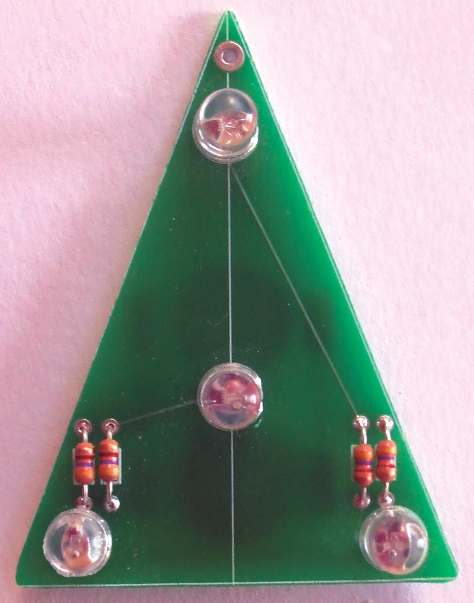
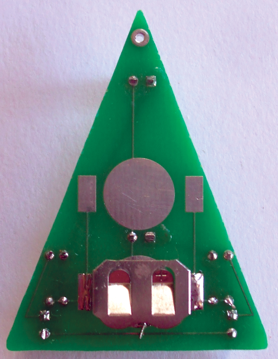
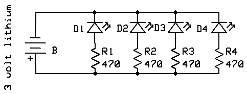
Okay, say you need some bling in a pinch. Push the four resistors through the top of the board and solder. Push four 3 mm LEDs through the top of the board, putting the long leads into the square pads (Figure 7). Turn the board over and solder the battery holder. You just surface-mounted (Figure 8)!
Put a battery in and the earring should light.
 |
| Figure 9 |
FINAL COMMENTS
This circuit takes advantage of color-changing RGB LEDs. Unlike conventional LEDs that require external intelligence to make them blink or fade, these RGB LEDs have a microscopic microcontroller encapsulated witthin them. Subsequently, you only need to add as little as two volts of power to have a colorful fading/flashing light show (Figure 9).
Have a Merry Christmas. NV
SMT Earrings Parts List
| ITEM |
DESCRIPTION |
PART # |
QTY |
SOURCE |
| BH |
12 mm battery holder |
712-BAT-HLD-012-SMT |
1 |
Mouser |
| U1 |
PIC16F627 SM |
579-PIC16F627A-I/SO |
1 |
Mouser |
| LED 1 |
Green |
859-LTST-C170GKT |
4 |
Mouser |
| LED 2 |
Yellow |
859-LTST-C171KSKT |
4 |
Mouser |
| LED 3 |
Red |
859-LTST-C171CKT |
4 |
Mouser |
| LED 4 |
Blue |
859-LTST-C171TBKT |
4 |
Mouser |
| U2 - U3 |
NPN surface-mount |
863-MMBT3904LT1G |
2 |
Mouser |
| R1 - R2 |
10K |
RK73H2ATTD1002F |
2 |
Mouser |
| R3 - R10 |
100 ohm 805 |
RK73H2ATTD1000F |
8 |
Mouser |
| C1 |
.1 µF |
C0805C104K5RACTU |
1 |
Mouser |
| Ear wires |
|
|
1 |
Hobby Store |
| Battery |
Battery = CR1225 |
614-CR1225.IB |
1 |
Mouser |
| Board |
|
|
|
|
Simple Solder (Through Hole) Earrings Parts List
| ITEM |
DESCRIPTION |
PART # |
QTY |
SOURCE |
| BH |
12 mm battery holder |
712-BAT-HLD-012-SMT |
2 |
Mouser |
| Battery |
Battery = CR1225 |
614-CR1225.IB |
1 |
Mouser |
| Ear wires |
|
|
1 |
Hobby Store |
| LED 1 - 4 |
Fast Changing |
Rainbow LEDs 3 mm |
4 |
|
| R1 - R4 |
470 1/8 watt resistor |
299-470-RC |
4 |
Mouser |
Downloads
December2014_Newton-Earrings
PCB File, Hints and Tips, ASM, HEX, SCH files.