Recently, someone told me that they were having problems with their sump pump. The float had a leak causing it to sink, or else the float switch was bad. He wasn’t quite sure what the problem was. At any rate, the sump pump failed to work and resulted in a back-up that flooded their basement and ruined many of their possessions stored there. Another friend said that he wanted to control an elevated cistern that fed plants in a hydroponic garden.
After some thought, I figured that a unit could be designed that could do both jobs. Further, two different approaches could be used. One would depend on the conductivity of water; the second would rely on pressure created by the depth of a liquid in a vessel. Why, you ask, would both strategies be required?
The short answer is that diesel fuel, gasoline, oil, and other types of non-ionic fluids would not work with a circuit that required fluid conductivity. In addition, if the solution were highly caustic or acidic, it would dissolve the sensing electrodes.
The pressure sensing type of controller can be used with any type of liquid. So, you ask again, why bother with the ionic type of controller? For water and water solutions with dissolved fertilizer, for example, the ionic level controller works fine and costs much less than the pressure level controller. The pressure level controller has the advantage of working with any type of liquid, but is more costly to make.
The great advantage to either controller is that they don’t have any moving parts, linkages, floats, or switches that can stick or fail to cause a problem. Also, by negating the output of the logical window comparator, the user can incorporate a simple two-pin jumper to select either the sump or fill mode of operation. One unit can be used for either the sump pump or tank-fill function.
Theory and Operation
Please refer to Figure 1 (schematic of ionic level controller) for this discussion. The ionic sump-fill level controller uses two electrode pairs — low level and high level (jump ahead and check out Figure 7 A/B/C that shows the electrode assembly and control unit) — to detect the liquid level in a vessel such as a sump or storage tank. The electrodes are represented in Figure 1 as S3 and S4.
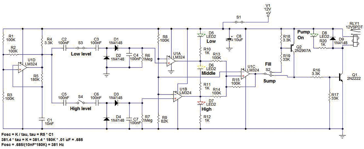
FIGURE 1.
In order to prevent the sensor electrodes from degrading in the ionic water solution due to plating effects, an AC (alternating current) source is used to stimulate the sensor electrodes. Op-amp U1D is configured as a square wave oscillator. Resistor R1, R3 form a Vdd/2 resistive divider for the + input of U1D. Resistor R2 provides positive feedback to the U1D+ input; R4 pulls up the output of U1D to Vdd. Resistor R5 and capacitor C1 form a delay time constant to the - input of U1D.
When the output of U1D is low, the + input of U1D equals Vdd * (R3//R2)/((R3//R2) + R1) = Vdd * 50K/150K = 1/3*Vdd. Resistor R5 discharges C1 until the voltage at U1D ≤ U1D+. The output of U1D switches from low to high. The U1D+ input switches to Vdd * R3/((R1//R2) + R3) = Vdd * 100K/150K = 2/3 * Vdd. Resistor R5 begins charging C1 until the voltage at U1D ≥ U1D+. This process repeats, producing a square wave at the output of U1D. With the values shown, Fosc = approx. (.685 /( R5 * C1)) = 381 Hz (400 Hz was the target).
The output of U1D is fed to capacitors C2 and C5 which are connected to one side of the low and high level electrode sensing pair, respectively. The other side of the low and high level electrodes connects to C3 and C6, respectively. Capacitor C3, D1, D2, C4, and R6 function as a charge pump. When solution allows current to flow from C2 to C3, C4 charges to indicate the solution level is at least as high as the low level electrode pair. Similarly, C5, C6, D3, D4, C7, and R7 detect the high level of the solution in the vessel.
Resistors R8 and R9 form a voltage divider that is half of Vdd - 1.5V (due to the limited output level of the LM324 op-amps). Whenever the voltage level on C4 or C7 is above the R8, R9 reference level, op-amps U1A and U1B (that work as comparators) switch from low to high. When both comparators are high, this overcomes the hysteresis of U1C and causes U1C’s output to go high.
The operation in the sump mode proceeds as follows. The sump level is below the low electrodes; therefore, C4 and C7 are discharged, and U1A and U1B outputs are low. This causes LED D5 to be ON indicating the sump level is low. U1C is low; therefore, RLY1 is OFF (so is the sump pump).
When the solution rises above the low level electrode pair, C4 charges and U1A’s output goes high. This turns OFF D5 and turns ON D6 (because U1B’s output is still low), indicating the tank level is somewhere between the low level and high level electrodes. U1C stays low due to its own positive feedback and the low state of U1B.
The +input of U1C = (Vdd-1.5V)* R15//R14/(R15//R14+R13) = 10.5 * 50/150 = 3.5V which is below the reference of 5.4V. When the solution rises above the high level electrode pair, C7 charges and U1B’s output goes high. This turns OFF D6 and turns ON D7 (because U1A’s output is still high), indicating the tank level is above the high level electrode pair. The +input at U1C is now (Vdd-1.5V)* (R15)/(R13//R14+R15) = 10.5 * 100/150 = 7V which is above the reference of 5.4V. This causes U1C’s output to go high that, in turn, activates Q1, RLY1, turning ON the sump pump. As the pump lowers the tank level, U1B goes low. This turns OFF D7 and turns ON D6, indicating the mid level.
The + input at U1C = (Vdd-1.5V)* (R14)/ (R15//R13+R14) = 10.5 * 100/150 = 7V which is still above the reference of 5.4V. So, that U1C’s output remains high, RLY1 stays ON, and the sump pump keeps running. When the tank level is lower than the low level electrode pair, U1A’s output goes low, D6 turns OFF, and D5 turns ON (indicating a low level in the tank). When U1A and U1B are low, the + input to U1C = (Vdd- 1.5V)*(R13//R14)/(R13//R14+R15) = 10.5*50/150 = 3.5V, causing U1D’s output to go low, turning OFF RLY1 and the sump pump.
S2 represents the three-pin jumper selector. The fill mode is selected by connecting the jumper from the output of U1C to R19 and the base of Q2. This negates the output of U1C so that when U1C is high (the tank level is high), Q2 is OFF and Q1, RLY1, and the fill pump or fill valve solenoid are OFF. When the tank is emptied below the low level, U1C goes low, which turns Q2, Q1, RLY1 ON to activate the fill pump or fill valve solenoid to refill the tank. The pressure sensor level controller performs the same sump pump or tank fill function, but does it in a different way. Please refer to Figure 2 for the following theory and operation discussion.
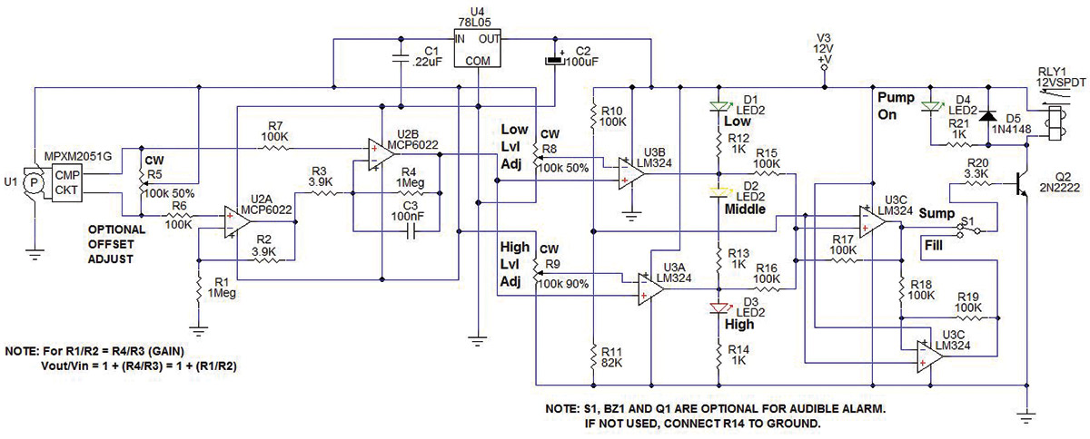
FIGURE 2.
The pressure sensor level controller uses a Freescale MPXM2051G sensor to measure the pressure created by the liquid level in a sense tube that goes from the top to the bottom of the sump or cistern vessel. It works like an inverted drinking glass when you place it into water. The liquid level inside the glass rises as the glass is put lower into the water. The air trapped inside the glass is equal to the water pressure at the bottom (lowest edge) of the inverted glass.
If a flexible tube was connected between the top of the drinking glass (the air bubble inside the glass) and a pressure sensor, the pressure measured would represent the liquid level, or depth of the liquid in the vessel. Instead of a drinking glass, a PVC (plastic), stainless steel, or glass tube is used to trap the air and is connected to the pressure sensor by a flexible tube. (Again, jump ahead and check out Figure 8 that shows the sense tube, flexible connecting tube, and the controller unit.) The type of sense tube material is determined by the type of fluid that is being measured.
As the pressure rises, the pressure sensor — which is based on a piezo-resistive bridge — puts out a small differential voltage that linearly corresponds to the pressure it senses. The math works out as follows.
The sensor has a full scale range of 50 kPa. Since 1.0 kPa (kilo Pascal) equals 0.145 PSI, the full scale range is 7.25 PSI. The MPXM2051G is ratiometric with the supply voltage. It is rated at 40 mV full scale with 10V excitation.
In this design, to accommodate the MCP6022 dual op-amp (used as a zero referenced, differential instrumentation amplifier) five volts of excitation voltage provided by a 78L05, U4 is used. This means that the full scale output of the sensor is 20 mV at 7.25 PSI. Therefore, since 1 PSI = 27.68 in of water, the full scale value of 7.25 PSI = 27.68 in *7.25 = 200.7 in of water for a 20 mV output; 20 mV / 200.7 in H2O = .09965 mV / in H2O. Thus, about 15 feet of water would produce about 18 mV of sensor output.
To get a full scale output from the differential amplifier, a gain of roughly 250 is needed. The gain is (R4/R3 + 1) = (1M/3.9K + 1) = 257.4, so the full scale output is 4.62V. This is fine because the MCP6022 is an RRIO (rail-to-rail, input and output) op-amp. The output of U2B provides a common input level to the U3A and U3B window comparators. Trim pot resistor R8 provides the low level reference to U3A, and trim pot resistor R9 provides the high level reference to U3B.
For a differential level of six inches of water, the differential voltage from U2B is about .09965 * 6 * 257.4 = 154 mV. To prevent noise from causing erratic operation, capacitor C3 in parallel with R4 form a low pass filter with a pole at 6.2832 * .1 µF * 1 Mohm = 1.6 Hz, or a time constant of .1 sec. Resistor R5 is included to adjust the offset of U2B output to around .3V to .5V, to increase the span of level adjustment.
Building the Sump/Fill Controllers
The intention here was to use inexpensive readily-available parts to build the controllers. All of the resistors are carbon film 5%. I chose a SERPAC model 032 plastic case which I have used in previous projects. The board was sized to use the mounting bosses in the case. For the ionic level controller, three wire terminals are mounted on the PCB (printed circuit board) and have slots in the side of the enclosure to allow for the insertion of the sense wires and the pump/solenoid load wires. The power jack (a 2.1 x 5.5 mm barrel jack) was mounted to the side walls of the case. A 12V/1A switching power adapter is used to provide the needed power for the controller.
The Gerber files for a two-sided PCB layout (refer to Figure 3, ionic; Figure 4, pressure) are available in the downloads.
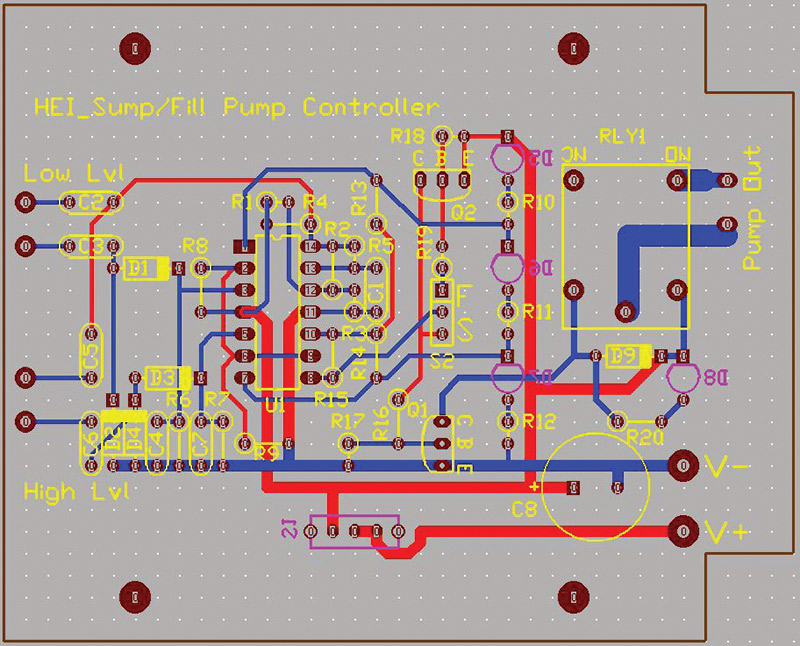
FIGURE 3.
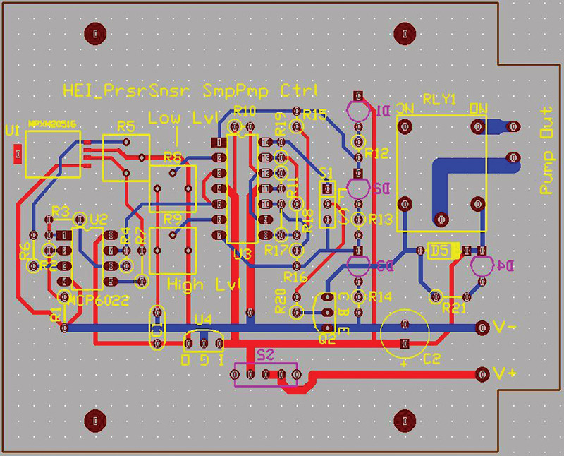
FIGURE 4.
For the build, point-to-point wiring was used on a prototype board from RadioShack and cut to the desired size to fit in the enclosure (refer to Figure 5, ionic; Figure 6, pressure). The components were laid out and positioned the same as on the PCB layout.
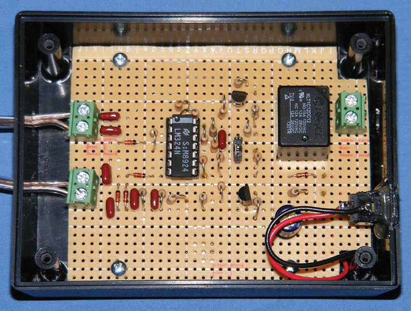
FIGURE 5.
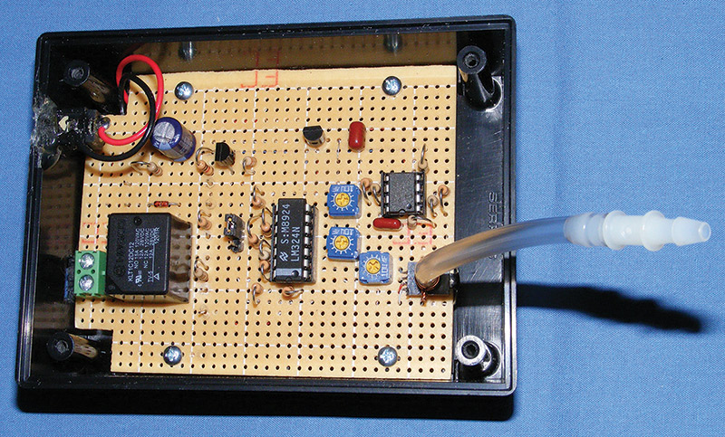
FIGURE 6.
After wiring and testing the circuit board, the AC out and input terminals were each connected to their sensor electrodes and load (pump). The power jack was installed into the enclosure, then the wires were connected from the board to the jack. The enclosures were machined using the respective machine labels that are available in the downloads.
Measure the center point of each side of the enclosure. The machine labels have center lines that are used to align the labels with the enclosure. The same must be done for the back panel of the pressure unit. The pressure unit has two labels: one for the enclosure front and one for the back. Both the switch and LED holes for the front of the enclosure and the holes for the adjustments and the pressure tube for the back panel are shown on the machine label as an X-ray view. The mirror image label is for the back of the enclosure.
Again, the actual labels used on the enclosure are available in the downloads. The labels will print out at actual size using 300 dpi in Paint Shop Pro. Since they are jpg files, you can use any photo program using the dimensions of 3.5” wide by 2.5” high for the labels, and 3.5” wide by 2.7” high for the machine labels.
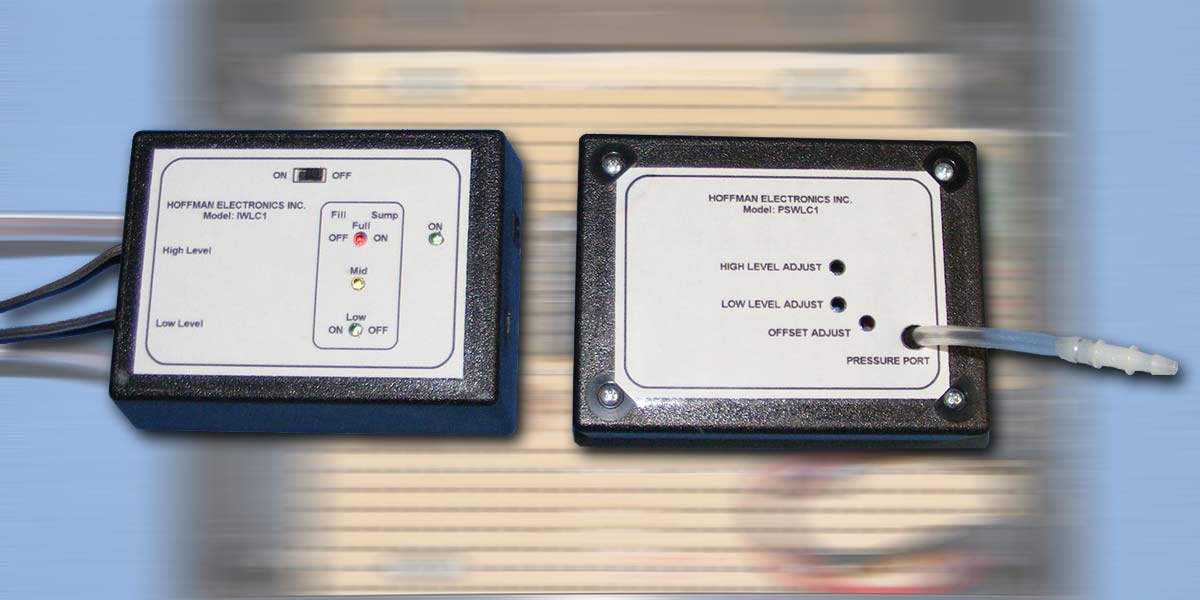
Several different types of electrode assemblies for the ionic level controllers were built and tested (Figure 7 A/B/C).
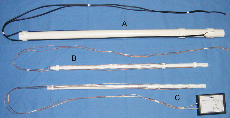
FIGURE 7.
One electrode probe (Figure 7A) was made using one inch and 1.25” diameter PVC pipe. The 1” pipe was used as a mounting shaft, while the 1.25” pipe was cut into two .75” rings used as the adjustable electrode holders.
The .75” rings were drilled and tapped with a 6-32 thread to accommodate a .5” x 6-32 nylon pan-head screw that is used to clamp the rings to the mounting shaft at the desired liquid level.
Two .0625” holes were drilled through the wall of the rings to mount a 14 AWG copper wire used as the sense electrode. The 20 AWG SPT-1 lamp wire was soldered to the copper sense electrodes, then run up the mounting shaft through a third ring at the top of the mounting shaft. This kept the wires taut along the shaft. The assembly worked fine, but seemed bulky and difficult to make.
A second version (Figure 7B) was built using a .5” and .75” diameter PEX tubing. A smaller 24 AWG speaker wire was used as the sensor wire. This assembly was much smaller, less costly, and worked fine too. The rings were machined like the PVC pipe and took some time. A third electrode assembly (Figure 7C) was built using a .5” PEX tube, 24 AWG speaker wire, and three nylon zip ties. This was the easiest to make. The only trade-off was that it is more difficult to adjust the liquid level height. Since the liquid level height adjustment only has to be done during the initial setup of the system, this is not too much of a problem. My preference is either version B or C.
The pressure based level controller required a sense tube to capture the pressure caused by a rising liquid level (see Figure 8).
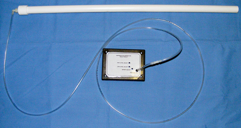
FIGURE 8.
For testing and development, a .5” PVC pipe was used. The bottom was cut off at an angle to allow the liquid to enter even when the tube was inserted to the bottom of the tank (in this case, a five gallon pail). A .5” PVC pipe cap was drilled and tapped for a .25” NPT pipe thread. A .25” NPT to .125” barbed elbow was threaded into the PVC pipe cap using Teflon tape to ensure an air-tight fit.
A .125” flexible tube (i.e., Tygon, or silicone, etc.) was used to connect the elbow to the controller unit. A short 3” length of tubing was attached to the pressure sensor using a 20 AWG solid copper wire wrapped twice around the tube at the pressure sensor, then twisted with pliers to cinch it tight. A dual .125” barbed fitting was used to connect the short tube to the long flexible tube coming from the sense tube elbow.
Testing the Liquid Level Controllers
To test the level controllers, the sump fill jumper was connected in the sump position on both controllers. A five gallon pail was used as the test vessel and filled nearly to the top with water (about 16”). A 12 VDC at 1A switching power adapter provided the necessary voltage to operate the level controllers. The ionic controller sense tube (shown in Figure 7C) was lowered into the tank to simulate the water rising in the sump tank. When the low level set of electrodes touched the water, the low level LED turned OFF and the mid level LED turned ON; the pump remained OFF.
Continuing to lower the sense tube into the water, the high level electrodes touched the water, the mid level LED turned OFF, the high level LED turned ON, the pump run relay and pump run LED turned ON. The sense tube was raised to simulate the pump lowering the water level in the sump tank. As the high level electrodes rose out of the water, the high level LED turned OFF, the mid level LED turned ON, and the pump relay and LED remained ON.
As the low level electrodes emerged from the water, the mid level LED turned OFF, the low level LED turned ON, and the pump run relay and pump run LED turned OFF. By adjusting the position of the sense electrodes, any low level and high level could be set. I placed the sump/fill jumper in the fill position. The unit worked to display the levels as before, but the pump run relay and pump run LED worked in the opposite way, i.e., they turned OFF when the high level was sensed and turned ON when the low level was sensed.
Next, the pressure based level controller was tested. The sense tube was inserted four inches into the water and held at that position. The low level pot was adjusted until the mid level LED came ON, then backed off slightly until the low level LED turned ON and the mid level LED turned OFF. The tube was then inserted 10 inches into the water and held at that level.
The high level pot was adjusted just until the mid level LED turned OFF, the high level LED turned ON, and the pump run relay and pump run LED turned ON. As the sense tube was withdrawn from the pail, the mid level LED turned ON and the pump relay and LED remained ON. As the sense tube was removed less than the four inch set point, the mid level LED turned OFF, the low level LED turned ON, and the pump run relay and pump run LED turned OFF.
Applications and Using the Liquid Level Controllers
Obviously, replacing the float and switch assembly in a sump pump tank is one application for the level controllers. Another would be for pumping out water from a dry well. A public water cistern which is mounted above ground to provide local water pressure could be refilled from a well whenever the tank level gets too low.
A top-down hydroponic feeding tank could be refilled to maintain a level between two specified points. The lower hydroponic catch tank could automatically refill to maintain a level between two specified points. Using a unit for the top and bottom tanks would allow for nearly complete automated hydroponic gardening. The only manual task would be adding fertilizer to the system as needed.
Another suggestion would be for maintaining the level of water in an aquarium. By plumbing a small fill line like those used for a refrigerator ice maker, the ionic level controller could energize a small solenoid valve to maintain the aquarium water at an optimum level for the filter pump and aeration system.
The pressure sensing level controller could be employed to fill an above ground fuel tank from an underground storage tank. The controller could be used to auto fill tanker trucks carrying fruit juices or vegetable oils. As was mentioned at the beginning of this article, any type of liquid can be level controlled using these two units to either fill or empty any size container.
The best part is that there are no mechanical floats or switches to deal with, and the level sensing is done remotely which keeps the electronics away from the fluids that are being monitored. As a reminder, the Gerber files and label files for this project are available below in the downloads. I hope you find this unit useful for many different applications. NV
Ionic Sump/Pressure Sump Parts List
| # |
QTY |
PART REF |
DESCRIPTION |
| 1 |
7 |
R1, R2, R3, R8, R13, R14, R15 |
100K resistor 5%, YAGEO, DK 100KQBK-ND or equiv. |
| 2 |
3 |
R4, R16, R18 |
3.3K resistor 5%, YAGEO, DK 3.3KQBK-ND or equiv. |
| 3 |
1 |
R5 |
180K resistor 5%, YAGEO, DK 180KQBK-ND, or equiv. |
| # |
QTY |
PART REF |
DESCRIPTION |
| 1 |
2 |
R1, R4 |
1 meg resistor 5%, YAGEO, DK 1.0MQBK-ND or equiv. |
| 2 |
3 |
R2, R3 |
3.9K resistor 5%, YAGEO, DK 3.9KQBK-ND or equiv. |
| 3 |
1 |
R5 |
100K trim pot, or equiv., DK CT6EP104-ND |
| # |
QTY |
PART REF |
DESCRIPTION |
| 4 |
2 |
R6, R7 |
1 meg resistor 5%, YAGEO, DK 1.0MQBK-ND or equiv. |
| 5 |
1 |
R9 |
82K resistor 5%, YAGEO, DK 82KQBK-ND or equiv. |
| 6 |
4 |
R10, R11, R12, R20 |
1.0K resistor 5%, YAGEO, DK 1.0KQBK-ND or equiv. |
| 7 |
2 |
R17, R19 |
33K resistor 5%, YAGEO, DK 33KQBK-ND or equiv. |
| 8 |
1 |
C1 |
.01 µF metalized poly, ± 10%, Panasonic ECQ-V1H103JL, DK P4513-ND or equiv. |
| 9 |
6 |
C2, C3, C4, C5, C6, C7 |
.1 µF metalized poly, ± 10%, Panasonic ECQ-V1H104JL, DK P4525-ND or equiv. |
| 10 |
1 |
C8 |
330 µF alum elec, 16V, Panasonic, ECA-1CM331, DK P5140-ND or equiv. |
| 11 |
5 |
D1, D2, D3, D4, D9 |
1N4148 silicon diode or equiv., DK 1N4148FS-ND |
| 12 |
2 |
D5, D8 |
LED, GRN (green), Lite-On LTL-4232N or equiv., DK 160-1083-ND |
| 13 |
1 |
D6 |
LED, YEL (yellow), T-1, Lite-On LTL-4252N or equiv., DK 160-1082-ND |
| 14 |
1 |
D7 |
LED, RED (red), Lite-On LTL4222N or equiv., DK 160-1081-ND |
| 14 |
1 |
JK |
5.1 x 2.1 mm barrel jack, DK CP-037A-ND |
| 15 |
1 |
Q1 |
PN2222A Fairchild Semi or equiv., DK PN2222AFS-ND |
| 16 |
1 |
Q2 |
PN2907A or equiv., DK PN2907ATFCT-ND |
| 17 |
1 |
RLY1 |
Relay, Hasco KLT1C12DC12, SPDT, 12A, 12 VDC, 300 mW or equiv. |
| 18 |
1 |
S1 |
SPDT slide switch, TE Connectivity, DK 450-1609-ND |
| 19 |
1 |
S2 |
Three-pin header, Sullens DK S1212-03-ND |
| 20 |
1 |
S2 |
Two-pin shunt jumper, DK 3M9580-ND |
| 21 |
1 |
U1 |
LM324N quad op-amp or equiv., DK 296-1391-5-ND |
| 22 |
1 |
PCB |
Printed circuit board, FR-4, two-sided, 2 oz copper (final), per Gerber files |
| 23 |
1 |
Enclosure |
Enclosure, SERPAC 032-B, Mouser 635-032-B |
Downloads
What’s in the zip?
Enclosure Labels
Gerber Files