After I had designed the RF generator, I started to toy with the idea of adding a sweep function to it. A couple of months later, I completed the design and prototype of this adapter that has relatively simple circuitry with a non-critical layout. It’s quite economical to build and draws its power through a short cable that plugs into a connector at the rear of the RF generator. This is a five-conductor cable that consists of three power leads and two interface leads. This combination is easy to use and has adequate performance. Although it's focused for use on my original generator design, the basic architecture can be modified for use with commercial RF generators that are based on varactor diode tuning.
There were many of these units manufactured during the ‘70s and ‘80s, and one may be sitting on your test bench now. One shortcoming is that my RF generator design has no overlapping RF bands such as my sweep generator has. This may not pose too much of an inconvenience and will be touched on later in this article. Again, the main body of this article will be directed towards my design but with occasional side notes pertaining to commercial equipment.
Theory of Operation
The basic architecture of this adapter generates a ramp for driving the generator’s varactor diode and also a synchronized ramp wave driving the scope’s horizontal axis. Features are Auto (ramp) or Manual tuning, Set Sweep Start and Stop Frequency, Variable Sweep Rate, and various alert lamps, plus an overload alarm (over-driving varactor).
Referring to Figure 1, the sweep ramp is formed by Q1, Q2, IC1a, and associated components.
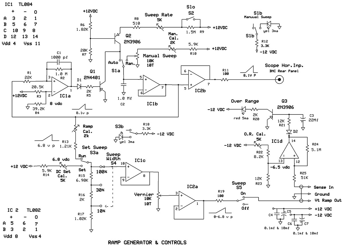
Figure 1.
Q2 is configured as a constant current generator; this current level is controlled by a fixed R6, R7 bias voltage on its base and the resistance of R8, R9 (in SLO position) and the 5K Sweep Rate potentiometer (pot) connected to its emitter. Varying the emitter resistance produces a change in the collector current which charges C2 in a very linear fashion and at a rate set by that emitter resistance value.
Obviously, this charging would just continue up to the supply voltage (+12V) and then sit there forever without some sort of reset incorporated. This is the function of comparator IC1a: to trigger at some arbitrary level (in this case, approximately 8 VDC) turning Q1 on hard and discharging C2. The C2 voltage drop immediately resets the comparator and then the whole process starts over again, thus producing a train of ramps at a rate set by the Q2 emitter resistance chosen. C1, R2 add some stability and hold time for completely discharging C2.
In this design, the sweep rate is approximately 10-100 Hz, and in SLO Sweep about 15 seconds per sweep. When S1a is switched to the manual position, the Manual Sweep pot produces a dot on the scope’s X axis that moves from zero to the full 10 major graticules on the screen. This will indicate the exact frequency at any position on the display, and comes in handy for closer examination and spot checking along that axis.
The ramp voltage or the DC voltage developed across C2 is buffered by IC1b, and further buffered by IC2b before entering the outside world through a BNC jack on the rear of the adapter unit to the oscilloscope X axis. The 100W resistor R11 is for stabilizing the op-amp under most any reactive load conditions it might encounter. You will see these stabilizing resistors in other outputs, so no further explanation of them is necessary.
The IC1b op-amp also feeds two other nodes: the discharge comparator at R1 and a calibrated attenuator S4 which is the Sweep Width Control. Just prior to S4, switch S3a is called out as the Set Sweep switch.
In the run position, the ramp voltage is adjusted by the 2K cal trimmer to a voltage peak that exactly equals the required varactor tuning voltage (Vt) span. In the set position, a DC voltage is set to match that voltage by adjusting the 5K cal trimmer. Also during final calibration, the Manual sweep pot will be calibrated with its 2K cal trimmer to match the DC voltage of the S3a Set position.
The Sweep Width switch, S4 is the coarse adjustment for setting the frequency span of the desired sweep. The 10K Vernier pot is the fine control used in conjunction with S4. This pot is buffered from S4 by IC1c for two reasons: First, I had one oddball op-amp left over from the initial design; and second, this was a good place to incorporate it as I don’t want the pot or anything else changing the load on S4.
Remember R15, R16, R17 are part of the calibration string. I want to keep their values isolated from any additional or changing loads. IC2a is wired as a buffer which insures very low impedance on this lead, and sends the Vt ramp voltage to the RF generator.
IC1d is a comparator that monitors the total Vt voltage applied to the RF generator varactor. This monitors the Vt output stage in the generator. Its trip point is set to the maximum voltage that the varactor was designed to handle. That voltage may be pure DC, Ramp AC peak, or the combination of both. Its purpose is to alert the user that an illegal operation has occurred and requires some reduction of the Vt voltage. This warning indicator is the only way you will know if the Vt is set too high and is being over-driven, resulting in a flat spot near the end of its sweep action.
The tripped comparator turns on Q3 hard, and drives the alert LED. C3 is incorporated to give some hold to that turn on time so as to allow the LED to stay on long enough to view it when the comparator is just starting to see the very peak of any ramp voltage that is present. S1b and S3b are the other halves of these DPDT switches and are used to turn on small LEDs to alert the operator to their status.
Strictly optional, but in the original design, there were several occasions of running sweep testing where I did not realize switches were not in their final proper positions to do so. Getting false results from the test was very confusing and annoying until I realized it was operator error. They add virtually no extra cost and add very little load to the power supply requirements (about 3 mA each).
Construction
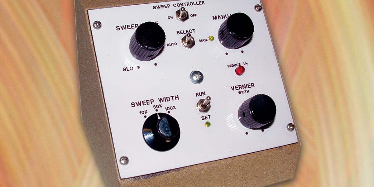
Referring to Figures 2 and 3, the completed front and rear views are shown.
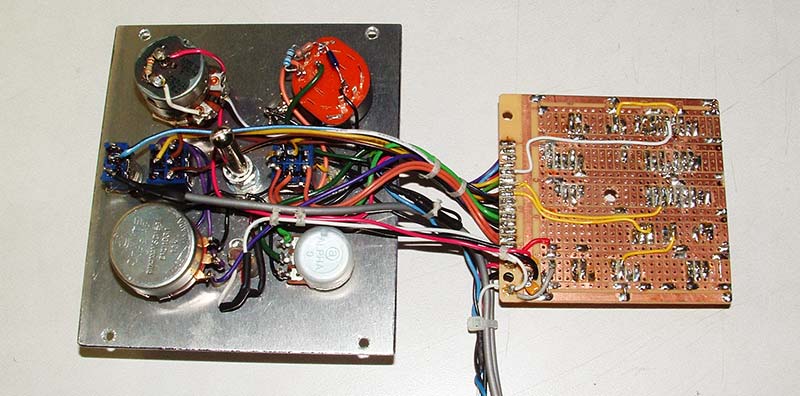
Figure 2.
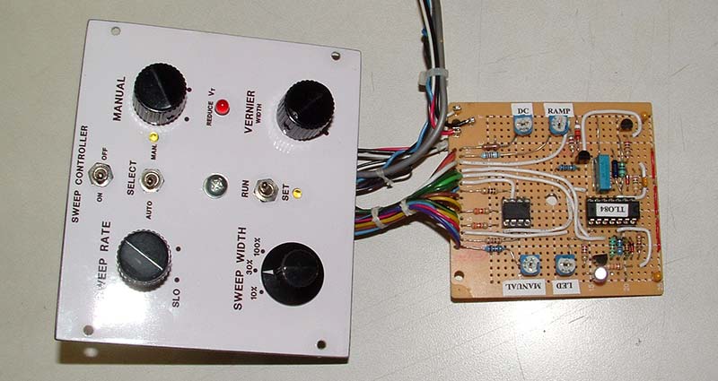
Figure 3.
The front panel measures 4.5” wide x 4.0” high. The circuit board measures approximately 3” square and is a modified RadioShack board (#276-168). I just love these boards as they readily accept DIP sockets and have power busses running right underneath them.
As seen in Figure 2, the board just folds over the back side of the front panel and is mounted to the front panel center post by one 8-32 screw. The depth of this whole assembly is approximately 2”. I built it this way so as to have easy access to the board component side for calibration and/or troubleshooting, and yet still have easy access to the underside with only the removal of one screw.
One thing to note in the photo is that the Manual sweep pot and the Vernier pots are shown as single-turn pots. These were ultimately changed to 10-turn pots of the same value (10 Kohms) for reasons I’ll describe later. I wanted an enclosure as small as possible, but with the control panel angled for comfortable operation, so the slope front style immediately came to mind.
At that point, I started cruising the Internet for a metal box that would be suitable, but at a lowest available price of $75, it was out of the question. Since this circuit did not require metal for shielding protection, I next tried plastic.
Prices were still too high, and nothing had a good fit for my front panel size. Since I decided I didn’t need a shielded box and I happen to be a woodworker, wood was my next logical choice. The material I used was some leftover scrap aircraft plywood about 0.15” thick.
I cut out six panel pieces and glued them together. Once cured, I finger-smeared a fillet of Bondo auto filler along all the inside corners for added strength. All in all, though, a rectangular box would be sufficient — especially with fold-down rear feet that would hold it at the proper angle when in use.
As can be from Figures 1, 2, and 3, the layout is fairly simple and straightforward. The cable leads to the generator were brought out the rear of the adapter box through a grommetted hole. The 14” cable was just laced every couple of inches and terminated in a seven-pin plug that looks similar to an XLR style. A mating jack was installed in the rear panel of the RF generator to accept this.
From there, the jack was wired to the proper locations on the control board as shown in Figure 4.
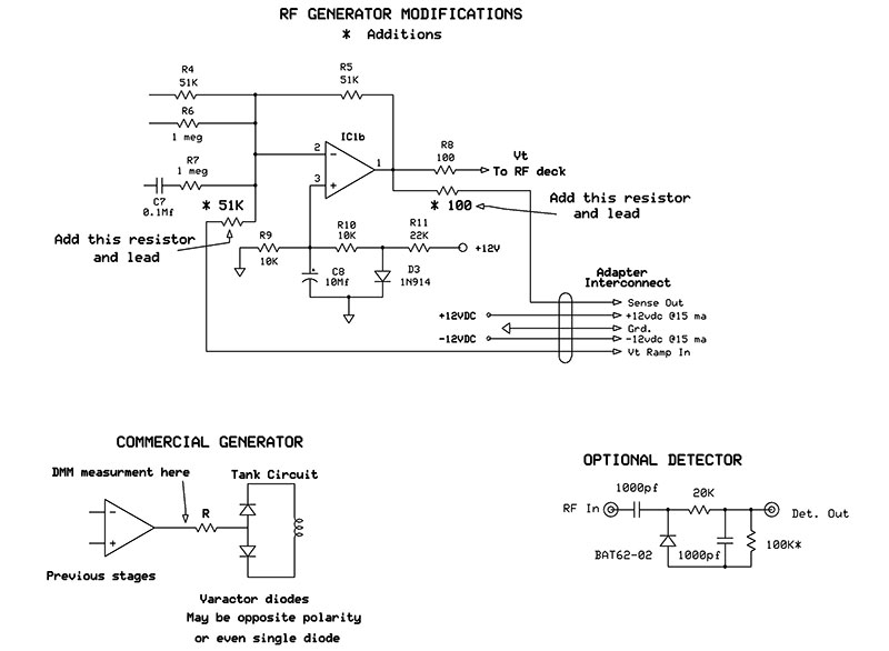
Figure 4.
Alternatively, you could just run leads out of a hole and use an outboard inline connector. Two resistors will have to be installed in the generator for the Vt and sense leads; you should have room left on the control board for these.
Too tight? Just solder one end of them snug to the board in a vertical position and tack the incoming leads to a short stub on the other end. Tie in the power leads wherever convenient. I did use shielded leads for the Vt/sense lines, and tied their shields to ground ONLY at the adapter unit end. This was probably overkill as all lines exiting the circuit board were designed for low impedance; generally less than 100 ohms.
The power required to operate the adapter unit is ±12 VDC at 15 milliamps. If you built your generator power supply as originally published, it can handle the added load. If not, then pre-check it with a suitable resistive load for those requirements to make sure it’s up to the task.
After the first prototype was completed and in the testing stage, it was apparent that the Manual sweep pot and Vernier pot needed more resolution than the single-turn pots originally installed. I wanted to replace them with three-turn pots in these locations.
They were hard to find; only 10-turn pots were commonplace on eBay and quite cheap. I did locate some three-turn pots from a small west coast distributor and promptly put my order in for them. I paid a bit more than I wanted to, but they were the only ones I could locate.
In the meantime, I wanted to continue my testing, and subbed in a pair of 10-turn pots I had in stock.
Funny thing is that by the time I received my three-turn pots, I was delighted with the way the 10-turn pots performed. I originally thought these would have required too much fiddling around to adjust them. However, they were really not that bothersome — especially when you consider that they are basically for setting up the sweep parameters, and then just get on with the sweep testing at hand. The resolution is such that it overshadows any minor inconvenience of their usage.
Needless to say, the 10-turns won out and the newly acquired three-turns were stored away for use in another project. While we are on the subject of multi-turn pots, I have to mention that about a year ago I replaced the fine-tuning control on my RF generator with a five-turn pot and it made a world of difference in tuning to an exact frequency — especially on the higher bands. You may want to do the same, as it is well worth the effort.
There are a fair amount of wires interconnecting the circuit board and front panel. I wanted to bundle them, yet easily be able to identify them at the other end by color-coding them. Having only seven or eight colors to choose, I quickly ran out of options.
So, I used a trick from the past to reuse the same colors by marking them with a continuous stripe. Clamp one end of the wire in a vice and while drawing the wire tight, trace a line down its length with a black felt tip pen. A blunt one works the best and one pass is adequate. Additional passes will remove more ink than they lay down.
Several precision metal film resistors are used in this circuit. Their actual ohmic value is not super critical, and near values may be used as long as they are within a few percent of the schematic values. Basically, they are used for their tighter temperature stability. Resistors R15, R16, and R17 can be off value somewhat, but the total of their combined resistance should be close to the design value of 10K as this is part of the calibration string.
After completing construction, check all controls for operation. If they are in the ball park, you can proceed with calibration.
Calibration and Operation
The original design of my RF generator calls for a Vt +0.6 VDC to -6.2 VDC which is a span of 6.8 VDC. Due to component tolerances, this could vary from unit to unit. For now, let’s assume that they are all identical to establish a standard of calibration and test setup procedure. I only mention this if your situation is slightly different and the calibration voltages might have to be changed.
I tried to keep the calibration pot resistance small in relation to the overall strings of resistors associated with them. This is due to the fact that they would be the most unstable resistance of those networks, and I wanted the 1% metal film resistors to make up the bulk of the load because of their superior stability. So, if you run out of pot travel in the calibration procedures, you will have to go up or down in value from the associated resistor of that particular string (i.e., R10, R13, R14, R22).
Begin the calibration procedure by turning the Manual sweep pot and the Vernier fully clockwise; S4 at the 100% position. Place S1a in the Auto position, S3a in the Run position, and the Sweep Rate at mid position. Scope probe IC1b’s output; you should see a very linear ramp of about 8V peak. Place the scope probe at the wiper of S4 in the 100% position and adjust the 2K cal pot that feeds this switch for 6.8V peak.
Now, place S3a to the Set position and adjust the 5K pot feeding that Set position for a DC voltage exactly the same level as the sawtooth peak (6.8 VDC). Set S3a back to the Run position and S1a to the Manual position. Adjust the 2K cal pot feeding that control for exactly the same voltage as the previous DC voltage (6.8 VDC).
Now, the Auto sweep level (ramp) and Manual sweep level (DC) will always track each other exactly, no matter how the testing setup is arranged. Of course, the scope trace and Vt ramp are always in sync by virtue of being locked on the circuit board. Leave these controls set as-is for now as they will provide the Vt on the sense lead to perform the next step.
To calibrate the over-range LED, you will need the RF generator connected and both its tuning controls fully counter-clockwise. You should see about -6.5 VDC at the sense lead input to the adapter. Adjust the 5K cal pot feeding IC1d in a direction to turn off the LED. Then, slowly rotate in the opposite direction until it just starts to turn on. There will be a small amount of hysteresis here which is intended.
This ends the calibration. These pots will never again need adjusting other than troubleshooting or periodic calibration checks (every five years?). At this point, I will just do a “drive-by” on each control from the top to the bottom of the front panel:
ON/OFF: S5 disconnects the Vt out signal output.
SWEEP RATE: Varies from 10 to 100 Hz; 15 seconds per sweep when S2 is in SLO position.
SELECT: Connects ramp to Vt out in Auto position; pure DC to Vt out in Manual position.
MANUAL TUNE: Applies DC only to Vt out and moves a spot across the entire scope’s X axis.
SWEEP WIDTH: Coarse adjustment of the total frequency span desired; % of RF band in use.
VERNIER: Provides a fine adjustment of the Sweep Width setting.
RUN/SET: S3a is used in conjunction with the RF generator and is for setting the start and stop frequency of the sweep.
The setup for testing requires both instruments to be connected together and sufficiently warmed up. If your generator does not have an internal frequency counter, one will need to be connected externally. Connect the adapter Scope Output to the horizontal input of your scope and adjust the scope for exactly 10 full graticules in length. With the RF generator’s tuning controls at the full CCW position, switch to the RF band of interest.
On the adapter unit, set S1a in AUTO position and S3a in SET position. Set the Vernier at the minimum (CCW) position. Select the S4 SWEEP WIDTH control for the approximate span of the RF band selected.
For example, if you were using the 5-12 MHz range and were only interested in a 2 MHz portion of that band, you would place this on 30% giving you a 2.1 MHz maximum span (12-5 x 0.3 = 2.1). These % settings apply to any portion of that band whether it is upper, lower, or middle.
Adjust the RF generator’s tuning controls for the desired start frequency and then adjust the adapter’s VERNIER control for the desired stop frequency. Reset S3a to the RUN position. Connect the RF generator to the input of the DUT (device under test) and the output of the DUT to the scope’s vertical input and begin testing.
Obviously, since the scope trace data isn’t labeled up like a full blown spectrum analyzer, you will have to be doing some simple math in your head during any testing. If you work in units of ‘10s,’ it’s really a no-brainer.
Let’s apply this to the above setup. We want to examine a narrow band pass filter with a moderate “Q” in the 11 MHz range. We have adjusted the SWEEP WIDTH CONTROL for 30% of any given portion of the 5-12 MHz band. We would like a center trace frequency of 11 MHz and probably a sweep width of 100 kHz per graticule division, giving us a total span of 1 MHz which will require a 10.5 MHz to 11.5 MHz actual span.
The start frequency of 10.5 MHz will be adjusted with the RF generator controls, and then the stop frequency of 11.5 MHz will be adjusted with the adapter’s VERNIER control. In an ideal world, the center graticule frequency would be exactly 11.0 MHz with this setup, but in reality — due to inherent non-linearity in the varactor — it may be off the mark. This may be of no concern in wide bandwidth filters, but is more important in narrower filters. This is where switching S1a to Manual sweep control comes into play.
Now, we can move a dot across the screen and land at any point on the trace. Since it tracks the ramp precisely, we can read the frequency that the Auto mode reads whenever its ramp would cross that given dot location. In my experience, if the dot planted on the exact midpoint of the trace and the desired center frequency was in error, the scope trace could be shifted slightly to center everything up.
Rarely would it require more than a fraction of a division, and a slight shift would not affect the test nor lose but a small fraction of the total trace due to a very small part of it being shifted off screen. However, the wider the band pass of a given DUT, the less important exacting frequencies become.
Back to our test. Our display shows a flat topped pass signal with a 3 dB reduction on graticule lines 4 and 6. Now we know that our filter has a band pass of 200 kHz (two full graticules at 100 kHz per division) with a “Q” of 55 as per the common formula of center frequency divided by the band pass of the 3 dB corner frequencies. What the sweep trace will really show is the symmetry and steepness of the skirts (how fast the filter builds or drops off the pass frequencies), plus any other spikes or aberration.
If all this setup sounds confusing, believe me it is not near as bad as shown. After an hour or so of playing around with the finished unit (even without a DUT), the operation will become almost intuitive. To clear the air a little more, I have taken scope pictures of a few tests I have run along with the actual setup.
Figure 5 is a display showing the final tuning of my high fidelity AM radio’s 455 kHz IF strip.
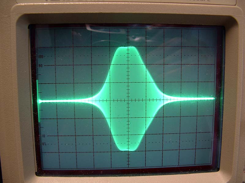
Figure 5.
These filters are stagger-tuned to broaden out the pass band and enhance the fidelity of the detector stage. The setup was: 455 kHz center frequency; 415 kHz start frequency; 495 kHz stop frequency; with a total span of 80 kHz at 8 kHz per scope graticule, and showing a 10 kHz band pass at the -3 dB corner frequencies.
Figure 6 is a sweep of a band rejection filter that I wanted to verify its location and performance: 19 MHz center frequency; 12.5 MHz start frequency; 26.5 MHz stop frequency: Total span 14 MHz at 1.4 MHz per major scope trace graticule. The filter has a band reject at 19 .1 MHz and a notch depth of 28 dB with a Q of 4.3.
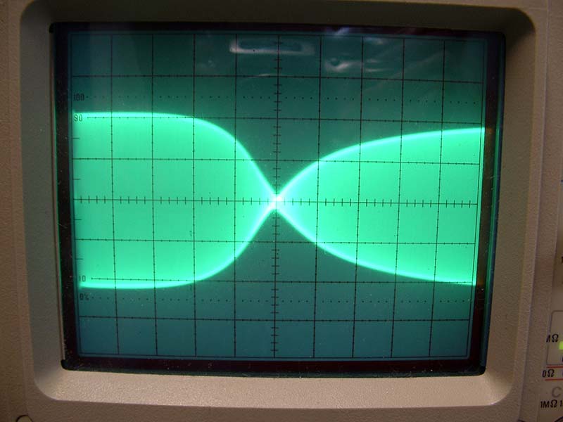
Figure 6.
Figure 7 is a sweep of a 100 MHz wideband amplifier I recently completed: 110 MHz center frequency; 60 MHz start frequency; 160 MHz stop frequency; with a total span of 100 MHz at 10 MHz per major scope graticule.
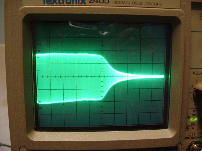
Figure 7.
It just starts to roll off at 108 MHz. Considering I needed to know the performance here from “DC” to well beyond 100 MHz, I had to begin with the lowest RF band and just spin the RF band switch right on through to the last position. All were run at 100% sweep, and due to the excellent leveling of the RF output, this displayed a reliable presentation from band to band. When checking any wide band response of a DUT, use this method. All lower bands here displayed a flat response.
Figure 8 is the same setup as in Figure 7, only this time with a detector probe (as shown back in Figure 4) attached to the output.
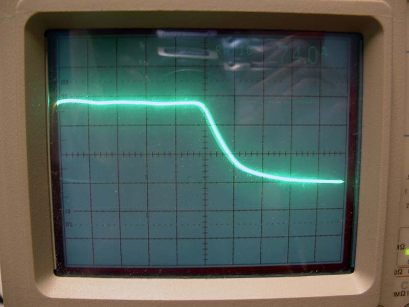
Figure 8.
I built two of these probes: One is constructed in a very small metal enclosure with BNC connectors on each end and the input terminated into a 50 ohm impedance. The other was built inside a felt tip marker housing with shielded leads and terminated with a BNC connector. Although you definitely want a Schottky type diode here, after experimenting with several, the BAT62 was the winner. This gives fairly linear performance down to 0 DBM levels (about 600 mv p-p), and then enters its square law region where response starts to drop off rapidly.
Some Words on Sweep Linearity
To begin, sweep testing is not an exacting science. In an ideal world, as the scope’s horizontal display is traveling along its 10 major divisions of length, the corresponding generator frequency would be in an exact step to those divisions in regards to linearity. This would require that all “major players” in all these devices were perfectly linear. Any scope manufactured in the last 40 years probably has a near perfect ramp driving its sweep trace. The adapter’s Vt ramp is perfectly linear. Now comes the weak link in the chain: the varactor diode.
Varactors do not have good linearity as far as their capacitance value vs. the applied bias voltage (Vt). They all tend to have a sag or bulge somewhere in their range of Vt. There are different methods to partially compensate for these errors in the Vt driving circuits, but none of them can completely correct this shortcoming.
There are other methods to correct this by using servo control that analyzes the non-linearity through a separate and parallel circuit path, establishes an error signal, and feeds it back to correction amplifiers in the basic Vt circuitry.
Although this method has superior performance, it is very complex and expensive to build. Any further discussion of this subject is beyond the scope of this article, and beyond the degree of accuracy intended for a service grade instrument. The best I could do on this design was to stretch out the tuning bandwidth as far as possible, and still maintain a respectable linearity for that given bandwidth. Like most design work, it involves trade-offs.
After deciding on the optimum tuning range, I ran a series of linearity tests. There are different ways to do this. I chose to measure the frequency at each major scope graticule division (10 in all) as the sweep trace crossed them. I then computed the frequency error in percentage as to what it should be in a perfectly linear sweep.
I ran tests on each band at the 10%, 30%, and 100% sweep widths, with center trace frequencies always referenced to the center frequency of that particular band. I made measurements at each graticule division for the sweep widths just mentioned on each frequency band — 240 test points in all. I then averaged these for an overall specification. Here are my results:
100% Sweep (of total band): 1.2% average error and 2.4% maximum error.
30% Sweep (of total band): 0.2% average error and 0.4% maximum error.
10% Sweep (of total band): 0.02% average error and 0.05% maximum error.
As can be seen from this data, the narrower the sweep span, the greater the accuracy. Recall that where the best accuracy is required is in narrow band sweeping; wide band sweeping is not so critical — especially the farther we move away from the center frequency. Due to screen parallax and the thickness of the scope trace, it is unlikely that one could discern a readout much beyond 0.5% (1/4 minor division). For that reason, the errors of the 10% and 30% bands can almost be dismissed.
For examining DUTs which have very wide bandwidths, the setup would be 100% sweep; simply start at an RF band lower than necessary and run through the RF bands beyond what is needed, pausing at various responses in the slopes and expanding for closer examination. The RF generator has excellent flatness of output level, so band hopping will not affect the test. All in all, these specs are satisfactory for most of the tests you might run.
Conclusion
This sweep adapter was a nice fit for my RF generator design. For readers that have commercial generators, some changes are likely required. The basic circuit architecture will remain the same but modifications will have to be made for it to work correctly.
You first have to determine the varactor’s tuning range (Vt), which is usually about one octave of frequency. To do this, you will have to measure the Vt span applied to the varactor by connecting a DMM directly to the varactor bias resistor ON THE INPUT FEED SIDE as shown back in Figure 4. Ultimately, this may be the tie-in point from the adapter’s Vt output lead.
The feed resistor will usually be in the 5-100K range. Tune the generator through its full travel and make note of the voltage and span read. Due to the wide range of designs from different manufacturers, these bias voltages can be all over the map. They may be anywhere from five volts to 30 volts, and in a positive or negative direction, or even bi-polar. Once you have established the starting voltage and span, the adapter Vt out lead has to present that voltage to your particular generator.
Modifications could be as simple as an added op-amp here to scale, offset, and/or invert the voltage that the adapter currently outputs. A better way (if your skills are sufficient) would be to change gains, polarities, and inversions in the unit itself, thereby not having to add more stages. The maximum Vt spans that can be obtained with the adapter’s power supply are from -10.5 volts to +10.5 volts. Beyond that, you will need a separate higher voltage power supply which would only be used in the Vt output stage.
One word of caution here is that the Vt feed point must be carefully chosen due to unwanted voltage division of the internal and external Vts. It’s better if you can locate a tie-in point farther upstream from the varactor — especially a summing amp because there is no interaction of inputs at their summing point.
This is not rocket science, but if undertaken, you should have a certain knowledge and confidence of what is required here. It goes without saying, a good factory service manual or at least a schematic diagram is needed.
Before ending this article, I will again present a quick rundown for the sweep setup:
- Sufficient warm-up time for both units.
- Generator-RF band of interest.
- Adapter — S5 Sweep on; S1a in Auto position; Vernier control fully CCW.
- Generator — Set RF tuning controls for start frequency.
- Adapter — S3a in Set position; switch S4 for desired span; advance Vernier CW to stop frequency.
- Place S3a in Run position. Start testing.
Note: Manual tuning may be switched in or out at any given time for spot checking an exact frequency at any point along the scope X axis trace. This will not interfere with the setup already in place.
So, that’s it. I hope I have not left anything uncovered here, but as I have done in previous articles, I’ve included my email address for any problems that might arise: [email protected]. NV
| PART |
DESCRIPTION |
PART |
DESCRIPTION |
| R1 |
22K* |
C1 |
1,000 pF MLC |
| R2 |
1.0 M* |
C2 |
1.0 mfd (Do not use ceramic or electrolytic) |
| R3 |
20.5K* |
C3 |
22 mfd electrolytic |
| R4 |
39.2K* |
C4, C6 |
0.1 µF |
| R5 |
2K |
C5, C7 |
10 µF |
| R6 |
1.82K* |
D1, D2 |
1N916 or equiv |
| R7 |
20K |
Q1 |
2N4401 |
| R8 |
510Ω |
Q2, Q3 |
2N3906 |
| R9 |
1.5M* |
IC1 |
TLO84 |
| R10 |
5.9K* |
IC2 |
TLO82 |
| R11 |
100Ω |
Optional detector diode |
BAT62-02 |
| R12 |
3.3K |
S1, S3 |
DPDT min toggle switch |
| R13 |
1.21K* |
S2 |
SPST (part of Sweep Rate pot) |
| R14 |
5.9K* |
S4 |
SP three-position wafer switch |
| R15 |
6.98K* |
S5 |
SP min toggle switch |
| R16 |
2K |
Sweep Rate pot |
5K linear w/sw |
| R17 |
1.02K* |
Manual Sweep pot |
10K/10T |
| R18 |
3.3K |
Sweep Vernier pot |
10K/10T |
| R19 |
100Ω |
Manual Calibration |
2K trimpot |
| R20 |
2K |
Ramp Calibration |
2K trimpot |
| R21 |
12K |
DC Set Calibration |
5K trimpot |
| R22 |
8.2K* |
Over-Range Calibration |
5K trimpot |
| R23 |
12K* |
|
|
| R24 |
5.1M |
|
Note: All resistors 1/4 watt @ 5% |
| R25 |
51K |
|
* 1% resistors |
SWEEP ADAPTER PARTS LIST