I find medical instruments like an ECG-EKG unit really fascinating. To be able to watch the electronic firing signals of a heart is mesmerizing and informative. The patterns tell you, for example, if you have arrhythmia (irregular rhythm or beat), too little or too much potassium in your blood, ischemia (a lack of blood flow to the heart muscle), damaged heart muscle (after a heart attack), fibrillation (when the heart just quivers and doesn’t fully pump), your heart rate, and much more. For the rest of this article, I will refer to the unit as an ECG (Electro-Cardio Gram).
If you’ve ever had an ECG at your doctor’s office, the bill for it can run anywhere from $100 for a standard three-lead test to $1,200 for a 12-lead test. Being an engineer and inventor, I wanted to see if I could come up with a really good low cost way of designing and building my own unit so I could check out my own heart signals. The effort was fraught with design trial and error, and many lessons to be learned along the way. The result was better than I ever imagined.
For parts costing less than $50, I built an ECG unit that plugs into my laptop computer’s microphone input jack and displays stunningly clear ECG waveforms. It uses a single quad RRIO (rail-to-rail, input-output) op-amp and features a red LED that blinks with each heartbeat.
This project is easy to build and can be used to explore the fascinating field of electrocardiography. There are many lessons to be learned from the design and the methods used in this project.
How the Circuit Works
The schematic diagram (Figure 1) shows the MCP6024 quad op-amp which is the “heart” of the unit.
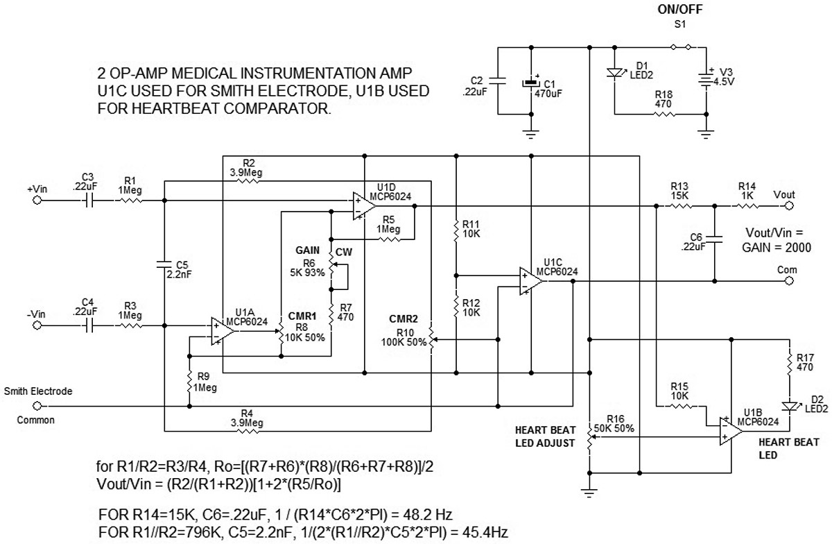
FIGURE 1. Schematic diagram.
U1A and U1D are connected as a common referenced differential instrumentation op-amp. This means that if the +Vin and -Vin input voltages are equal, the output voltage will be the same as the reference voltage. The MCP6024 is the quad RRIO op-amp. The input is linear from Vss-.2V to Vdd+.2V. Three AAA batteries (4.5 volts) provide the supply voltage to the MCP6024.
To maximize the voltage swing, the amplifier bias (or reference level voltage) is set by R11, R12, and U1C. The values selected give a reference voltage of 2.25 volts or Vdd/2, which is roughly half of the linear range. The output of U1C is the “ground” reference for the unit, and is connected to the output jack, the case ground, and the common Smith electrode. It also serves as the positive input reference for U1A and U1D — the two op-amps used as the common mode referenced differential instrumentation amplifier. The green LED shows if the power is on and the relative health of the batteries.
There are many topologies for circuits that do the same thing. I chose the ground referenced dual op-amp instrumentation topology for a couple of reasons. First, it minimizes the parts count, and “ground” references the output. In this case, the ground is the Vdd/2 output of U1C, which allows the output to swing above and below the common ground, and allows for the unit to “float” at the level of the display device whether it is an oscilloscope, laptop computer, tablet, or smartphone. The minimum number of op-amps used by this topology allows the fourth unused op-amp to be connected as a comparator to flash a red LED when a heartbeat occurs.
The second reason for using this topology is that it provides a simple way to adjust the CMR (Common Mode Rejection) of noise introduced at the inputs from the electrodes attached to the patient. This noise is due to RF sources, sparking motor brushes, but mostly from 60 Hz AC line noise induced from wiring in a building. To reduce the input noise while providing high gain amplification to the differential heart signals, two circuit techniques are employed. One is the CMR; the other is low pass filtering. In this design, the filtering is done at the input to the instrumentation op-amps, and at the output before it’s delivered to the display device. R1-R2 and R3-R4 form divider networks that provide bias voltage to the + inputs of U1A and U1D, and limits the input from the patient’s electrodes.
Potentiometer R10 allows for the two divider networks to be balanced exactly to cancel out any common mode input signals. It is designated as CMR2. To assist and filter the input, C5 connects the + inputs of U1A and U1D. If you take the parallel impedance of R1 and R2 (about 800K) times 2 (for R3 and R4), and design for a low pass cutoff around 50 Hz, it yields about 2 nF. Using the nearest standard value, 2.2 nF, Fo= 1/(2*pi*Rtot*C5) yields a low pass frequency of 45.44 Hz.
While we are discussing the inputs, C3 and C4 are very important. The RC time constant for the input is 220 nF * 4.9 Mohms = 1.08 seconds. Any signal occurring in .1 seconds will pass through easily. Any DC voltage will be blocked. This is very important. It turns out that the electrodes and the acids on your skin act as tiny batteries. They create differential voltages that will be amplified and run the output to saturation which buries the heart signal. By connecting the third Smith electrode, this gives the patient a “common” reference which greatly reduces noise and improves the common mode rejection. Capacitors C3 and C4 pass the heart signals but block the electrode induced DC voltages. Thus, the output stays near the common reference ground, and full gain of the heart signals is obtained. R13 and C6 provide for a second low pass filter at 48 Hz prior to the signal passing to the display device.
In addition to R10 (CMR2) which is used to balance the input divider network, an additional CMR1 adjustment is made via R8. Potentiometer R8 adjusts the CMR of U1A and U1D by balancing the ratio of R9 and R5, which further improves the overall CMR of the circuit. R7 in series with potentiometer R6 allows the gain to be adjusted from approximately 900 to 4,200. The needed gain is between 2,000 and 3,000. This is dependent upon the type of electrodes used, area prep (alcohol swabs to clean oils and dead skin from electrode area), thickness of patient’s skin, level of subcutaneous fat, patient’s physical size, etc.
Op-amp U1B is used as a comparator to flash the red LED D2 whenever the QRS complex (heartbeat signal) is observed. Potentiometer R16 adjusts the threshold reference of U1B; the -input of U1B connects via R15 to the output of U1D. Adjusting R16 to a couple of tenths of a volt above the common causes U1B’s output to be high and LED D2 off. Whenever the heartbeat is detected, the QR portion of the signal goes to nearly one volt depending on the amount of gain, etc., causing U1B to go low and flash LED D2.
Author's Note: If a smoother waveform is desired, C5 could be increased to 4.7 nF or 10 nF, to provide a break frequency of 20 Hz or 10 Hz, respectively, to reduce noise. Likewise, increasing R13 to 33K would reduce the output break frequency to 22 Hz, further smoothing the waveform noise.
Building the Unit
The Parts List includes the numbers and sources for all of the parts needed to build the unit. Also provided (in the downloads) are the Gerber files for the printed circuit board (PCB). I built my unit using a RadioShack 276-147 general-purpose PCB. The Gerber file check print (Figure 2) was used to place the components and wire wrap wire to connect any parts that were too far apart to use the part leads to make the connection.
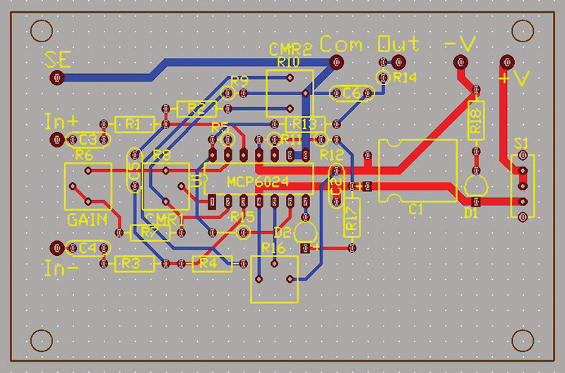
FIGURE 2. PCB layout.
Also, since the PCB I designed was two-sided, the wire wrap allowed me to cross over wires and make connections that wouldn’t have been possible on the single side of the board (see Figures 3 and 4).
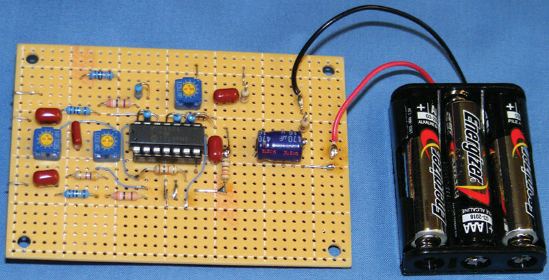
FIGURE 3. Top side of PCB.
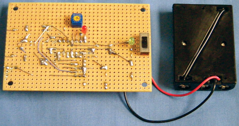
FIGURE 4. Bottom side of PCB.
Resistors R1- R3 and R5-R9 need to be matched in value. It doesn’t matter if the value is lower or higher than one meg, just that they match within one digit, i.e., 2 at 994K, or 2 at 1003K. The same applies for R2-R4 — 2 at 3.92Meg or 2 two 3.89Meg — just so they match. The rest of the values are not critical.
Be sure to use metal film 1% resistors where specified. Carbon 5% resistors can be used for the rest of the circuit. Be sure to check all your wiring and definitely use the 14-pin socket for the MCP6024 so you can replace it if needed. Check all the ohms between pins against the schematic before applying the battery, and then check the plus input of U1C (pin 10) compared with ground. It should read about 2.25 volts. The voltage across C1 should read about 4.5 volts; higher for new batteries, lower for used batteries. If that all checks out, turn the power off and install the MCP6024, being careful to observe the pin 1 placement. If you turn it around 180 degrees, you will fry it upon applying power.
I printed multiple copies of the label file, available in the downloads, and used one for the drill and filing guide on the enclosure (Figure 5).
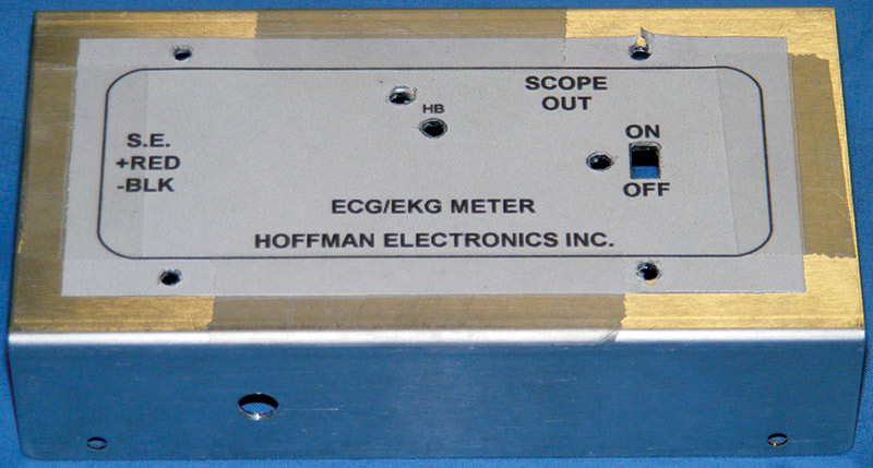
FIGURE 5. Label used as drill guide for machining enclosure.
Align a label equidistant from the sides and ends of the aluminum “U” channel (top). Tape it in place on four sides. Use a 9/64” drill bit for all the holes. Drill two holes in the slide switch rectangle and file out to the lines. Next, two holes need to be drilled on each side of the aluminum U channel. Each hole needs to be 1/2” above the bottom of the side flange.
Drill the electrode input jack and the output (Scope Out) jack hole using a 15/64” drill bit (for a tight fit) or 1/4”drill bit. The output jack should be below the Scope Out on the label. The electrode input jack should be about 1.75” from the front of the unit.
Building the electrode cable assembly is next. The goal was to make it simple to connect the cable to the unit using low cost parts. That is why the standard miniature stereo phone plug and jack were selected.
Cut a piece of two-conductor 28 gauge C1228 Carol coaxial cable about five to six feet long. Slide the plug cover over the wire before stripping and soldering the wire to the 1/8” phone plug. Solder the red wire to the phone plug tip lug; solder the black to the ring lug and the ground wire to the sleeve crimp lug. Crimp the ground wire around the cable jacket, then slide the plug cover over the plug and screw it tight.
Strip the other end of the cable jacket about .75” from the end. Strip 1/4” of insulation from the red and black wires. Leave the ground wire, but remove the aluminum foil wrap. Cut three 18” lengths of Carol C1156 RG174/U 50 ohm coaxial cable. Remove 1” of the jacket on one end of each cable. Push the braided sheath toward the jacket. Using a right angle dental probe, carefully separate the braided wires and pull the center conductor through the opening.
Stretch the braided sheath out. Strip 1/4” insulation off of the center conductor. Slide a 1/2” length of 1/8” diameter heat shrink tubing over the conductor. Solder the stripped center conductor to the red conductor; slide the heat shrink tubing over the soldered wires; then apply heat to shrink the tubing over the solder joint. Repeat this procedure for the black wire.
Last, solder together the ground shields from the three coaxial cables and the center conductor of the Smith electrode cable to the ground wire of the two-conductor coax cable (see Figure 6).
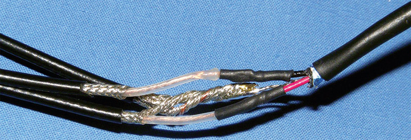
FIGURE 6. Cable assembly connection.
Next, place a 4” length of 1/4” diameter heat shrink tubing over the three coaxial wires and slide it over the soldered joints and their heat shrink tubing. About 1.25” should cover the two-conductor coax wire. Apply heat to shrink the tubing tightly into place, securing the three coaxial leads to the two-conductor coaxial cable.
Finally, strip about 3/8” from the center conductor of each cable and tin the wire with solder. Trim the braided ground shield off. Slide the outer insulation sheath so that it covers all of the ground wire’s braided shield. Insert the center wires of the coaxial cables into the electrode clamps that attach to the adhesive electrodes.
To do this, disassemble the electrode clamps by snapping off the housing, then remove the actuator lever. This releases the upper spring clamp. Remove the bottom metal strip from the clamp. Thread the center conductor into the slot in front of the spring clamp and replace the metal strip into the housing; then snap it in place. Place the upper spring clamp and replace the actuator lever.
Last, snap the top housing cover over the lever on to the clamp housing. Use a small jeweler’s screw driver to press the coaxial cable to the side of the clamp housing, wedging it under the rib. Fill the end of the clamp housing with hot melt glue to strain-relieve the coaxial cable and hold it in place. Finally, measure the resistance from the tip of the 1/8” phone plug to one of the electrode clamps and mark it with a “+” sign.
Measure the resistance from the ring contact of the phone plug to another of the electrode clamps and mark it with a “-” sign. The last clamp should be labeled with a “C” for common. Make sure that there are no shorts between the different clamps. The final assembly should look like Figure 7.
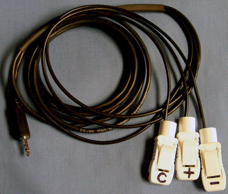
FIGURE 7. Finished cable assembly.
Use another copy of the label and laminate it for the ECG unit. After cutting out the label, laminate it with Fellows self-adhesive laminating sheets, leaving about a 1/4” border around the edge. It works best if you leave about a 1/2” border around the edge of the label.
After you burnish the laminating sheet to the label, cut the holes out for the trim pot adjustment, switch actuator, and LEDs using an Xacto™ knife. Now is the time to trim the edge of the laminate to leave the 1/4” border around the label. This corrects for any skewed alignment when laminating the label and provides equal and straight borders around the edge for a professional looking result.
When all the holes are cut out and you have dry-fitted the label to the unit, make sure that all the holes line up properly. Remove the laminate sheet backing, and carefully align and mount the label to the enclosure (Figure 8).
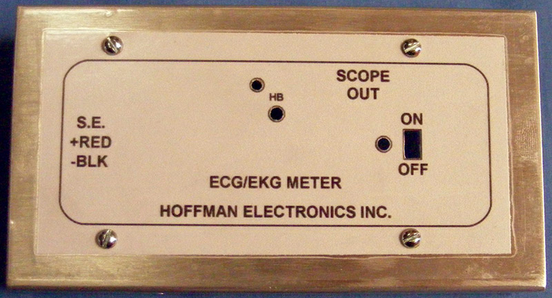
FIGURE 8. Laminated label applied to enclosure.
It may help to hold the aluminum up or back light the enclosure as you lower the label and align the holes with the enclosure. Burnish the label edges to insure the label seals well.
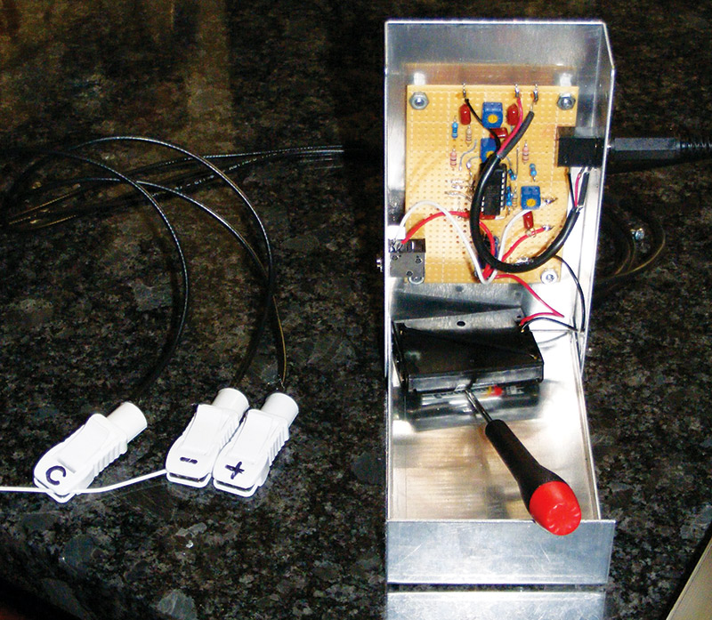
The PCB is mounted to the enclosure using four 4-40 x 5/8” (preferred) or 3/4” (easier to find) machine screws, four 4-40 by 1/4” nylon threaded spacers, and four 4-40 nuts. Place the machine screws through the label, screw on the threaded spacers, and tighten. Mount the PCB on the machine screws and secure with four 4-40 nuts (Figure 9).
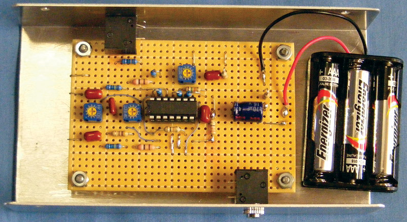
FIGURE 9. PCB installed.
Solder the red lead of the AAA battery pack to the V+ pad or the double soldered pins of the slide switch, and solder the black battery pack lead to the V- pad (Figure 9). At final assembly, a block of foam rubber packing can be used to prevent the battery pack from moving.
Finish the electrical assembly (Figure 10) by connecting some 24 gauge hookup wire from the circuit board to the output phone jack (white, common, to sleeve lug closest to aluminum enclosure; red, from R14, OUT, to the tip lug, closest to the common lug).
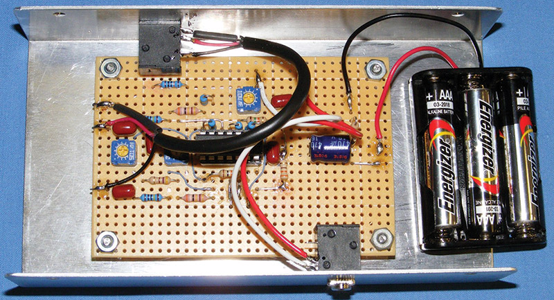
FIGURE 10. Final assembly connections.
Cut a 4” piece of two-conductor coaxial cable (Carol C1228). Prepare one end by removing 3/4” of the outer jacket. Then, remove the aluminum shield foil, leaving the ground wire.
Strip 1/8” insulation from the red and black wires. Prepare the other end of the cable the same way, but remove 1.5” of the outer jacket. Solder the shorter cable end ground to the common sleeve lug closest to the aluminum enclosure; the red lead to the tip lug next to the common lug; and the black lead to the ring lug.
Solder the other end of the cable to the PCB. Ground to S.E.; red lead to In+, C3; and black lead to In-, C4. Figure 11 shows the finished ECG unit, the 1/8” stereo patch cord, and the three-clamp electrode cable assembly.
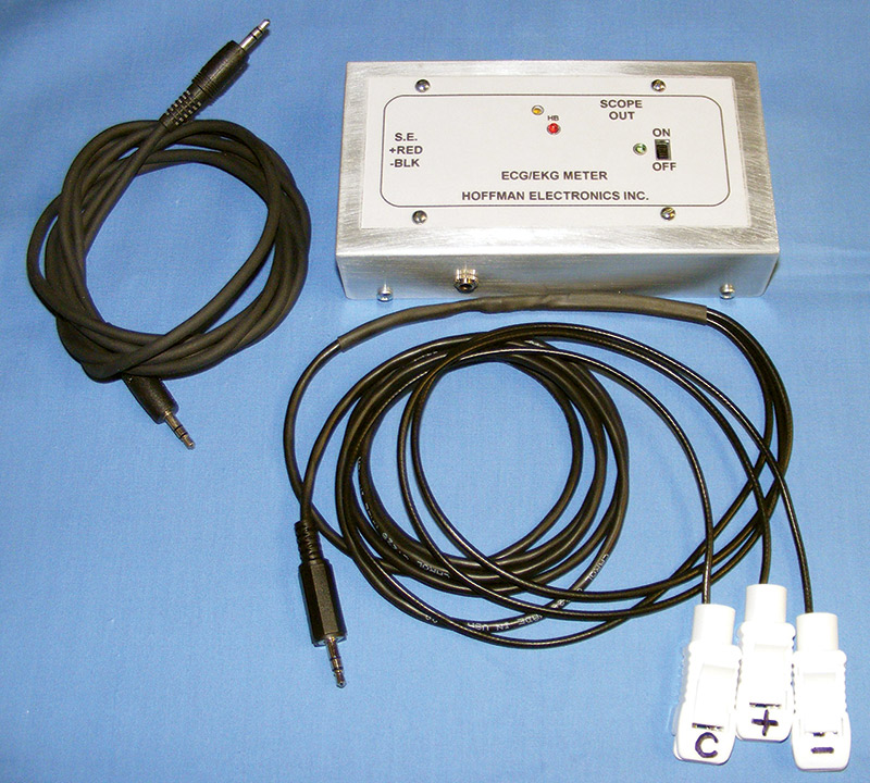
FIGURE 11. Finished unit.
Adjusting and Using the ECG Unit
Set all of the trim pots to their center position. Stand the U channel upright in the slot of the base as shown in Figure 12.
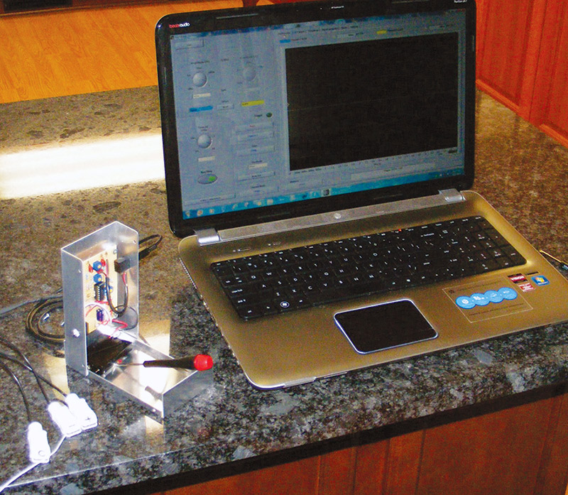
FIGURE 12. ECG setup for adjustment.
Download and install the Zietnitz Soundcard Scope app (version 1.46). Connect the ECG unit, SCOPE OUT, to the microphone input of a laptop computer using a short stereo 1/8” to 1/8” patch cable/cord. Connect the input cable to the ECG unit.
Open the settings tab of the Soundcard Scope app. Set the scope input to the external microphone (Figure 13).
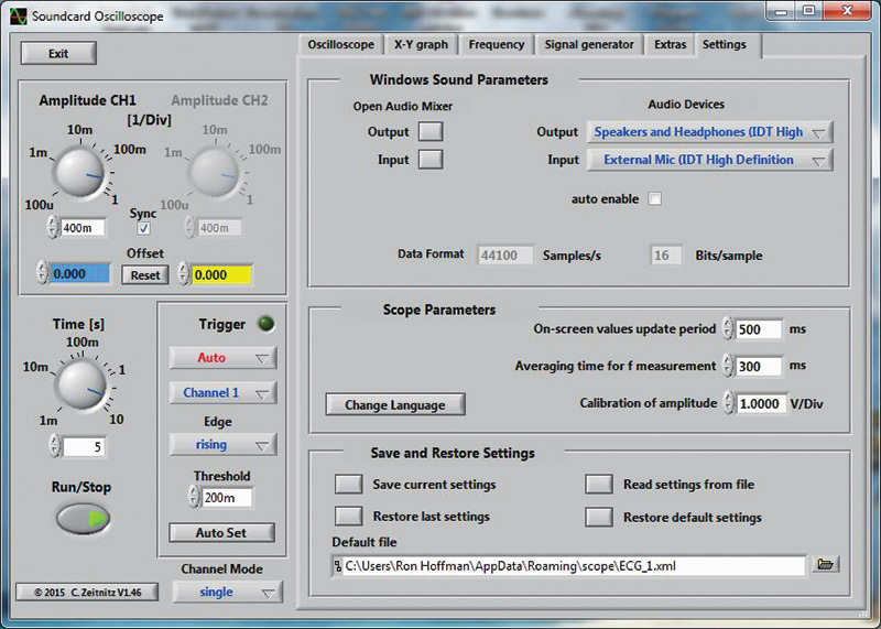
FIGURE 13. Zietnitz scope setup screen.
Adjust the channel 1 amplitude to 400m per division. Set the trace time to five seconds. Set the trigger amplitude to 200 mV. Adjust the ECG pre-amp gain pot to the 2:00 or 3:00 position between the center and max gain setting (this yields roughly a gain of 2,000).
Connect the red and black input leads together and hold them with your fingers. Adjust CMR2 until the scope trace is a minimum amplitude. Adjust CMR1 until there is a minimum amplitude. The unit is now ready for final testing and adjustment.
If the noise amplitude is too large, hold the common clamp in one hand and the ± clamps in the other hand. Then, adjust CMR2 and CMR1 for the smallest noise signal.
Using rubbing alcohol and a folded paper towel, clean three electrode areas as shown in Figure 14.
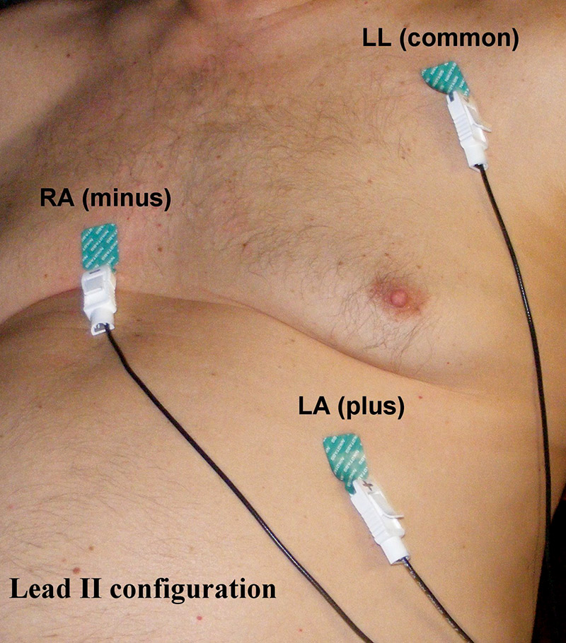
FIGURE 14. Nikotab elctrode placement.
Allow the areas to dry. Remove the backing from an adhesive electrode and place one on each cleaned area with the electrode tab (no adhesive) pointing down. Connect the S.E., common lead to the patient’s left shoulder; the black lead, minus to the right center chest area; and the red lead, plus to the lower left rib area. This electrode configuration is shown in Figure 15.

FIGURE 15. Lead II diagram.
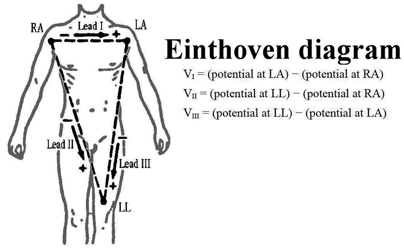
FIGURE 16. Einthoven diagram.
After a few seconds, the scope should show a pattern. Adjust CMR2 to minimize the noise in the pattern, then adjust CMR1 to further reduce the noise pattern. Adjust the GAIN pot so that the heart beat signal (QRS complex) has about a 1V amplitude.
The last adjustment is the heartbeat LED level. Turn the HB pot until the LED lights, then back off the adjustment to where the LED turns off but flashes each time the QRS complex is observed (on each heartbeat). It is important to note that the results are dependent on clean firmly attached contacts to obtain the clearest waveforms.
Reading the ECG Waveforms: What do They Mean?
The waveforms generated by the heart when it is beating can indicate many things. First, the distance (time) between beats indicates the rate the heart is beating. For example, if the time between beats is .75 seconds, the heart rate is 80 beats per minute, BPM, calculated by the formula, BPM = 60/time) = 60/.75 = 80. For .428 seconds, the BPM = 60/.428 = 140 BPM.
Other things like uneven beats (arrhythmias) show up as varied spacing between beats. This happens very often in older people (like myself). Inverted “T” waves may indicate potassium levels that are too low or ischemia (restricted blood flow) due to arterial plaques or blockages.
Other waveform anomalies can indicate damaged heart tissue, electrolyte imbalances, ectopic firing, atrial or ventricle fibrillation, etc. It is left to the reader to consult with a health care professional or cardiologist if they feel something is abnormal.
There are many texts available for understanding and interpreting ECG waveforms. Here are some for you to check out:
Conclusion and Final Thoughts
The unit worked beautifully when I tested it on myself, my wife, and friends. The tracings were clear and detailed. Some of the recordings I captured and saved are shown in Figures 17 and 18.
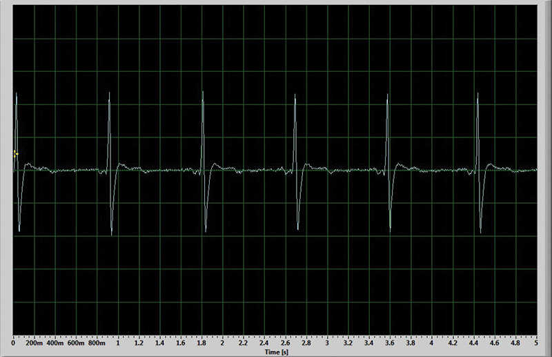
FIGURE 17. My ECG waveform.
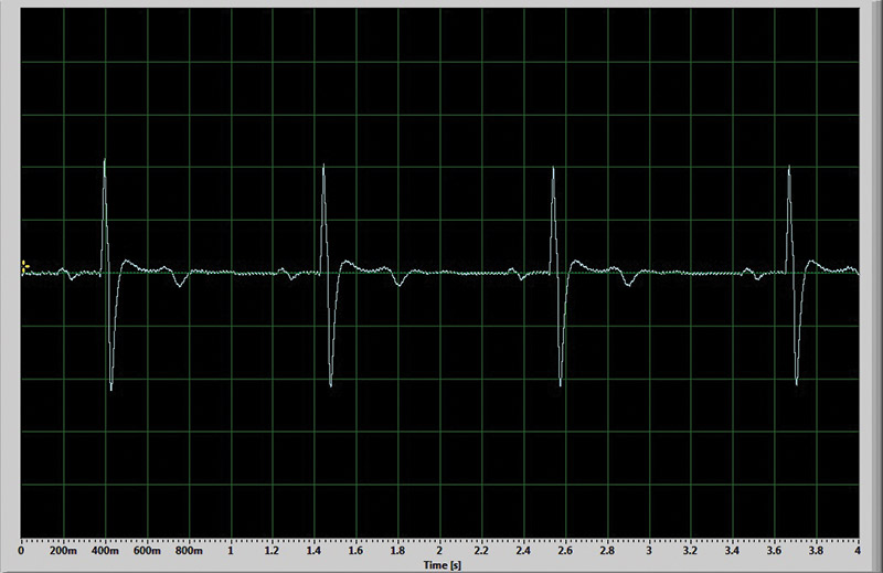
FIGURE 18. My wife’s ECG waveform.
I have included the actual trace recordings in the downloads. If readers have any questions, you may contact me at [email protected]. NV
| QTY. |
REF |
SOURCE |
DESCRIPTION/VALUE |
| 1 |
C1 |
Digi-Key |
470 µF alum elec, 16V, Panasonic, ECEA1CN471U, DK# P1170-ND or equiv. |
| 4 |
C2, C3, C4, C6 |
Digi-Key |
.22 µF metalized poly, ±10%, Panasonic ECQ-V1H224JL, DK# P4667-ND or equiv. |
| 1 |
C5 |
Digi-Key |
2.2 nF metalized poly, ±10%, Panasonic ECQ-V1H222JF, DK# P4555-ND or equiv. |
| 1 |
D1 |
Digi-Key |
LED, GRN (green), Lite-On LTL-4232N or equiv., DK# 160-1143-ND |
| 1 |
D2 |
Digi-Key |
LED, RED (red), Lite-On LTL-4222N or equiv., DK# 160-1140-ND |
| 4 |
R1, R3, R5, R9 |
Digi-Key |
1 meg resistor, 1/4W, 1%, metal film, YAGEO, 1.00MXBK-ND or equiv. |
| 2 |
R2, R4 |
Digi-Key |
3.9 meg resistor, 1/4W, 1%, metal film, YAGEO |
| 1 |
R6 |
Digi-Key |
5K, .5W linear trimpot, COPAL ELECT. CT6EP502-ND or equiv. |
| 3 |
R7, R17, R18 |
Digi-Key |
470 ohm resistor 5%, YAGEO, 470QBK-ND or equiv. |
| 1 |
R8 |
Digi-Key |
10K, .5W, linear trimpot, COPAL ELECT. CT6EP103-ND or equiv. |
| 1 |
R10 |
Digi-Key |
100K, .5W linear trimpot, COPAL ELECT. CT6EP104-ND or equiv. |
| 2 |
R11, R12 |
Digi-Key |
10K resistor, 1/4W, 1%, metal film, YAGEO, 10.0KXBK-ND or equiv. |
| 1 |
R13 |
Digi-Key |
15K resistor 5%, carbon film, YAGEO, 15KQBK-ND or equiv. |
| 1 |
R14 |
Digi-Key |
1.0K resistor 5%, carbon film YAGEO, 1.0KQBK-ND or equiv. |
| 1 |
R15 |
Digi-Key |
10K resistor 5%, carbon film YAGEO, 10KQBK-ND or equiv. |
| 1 |
R16 |
Digi-Key |
50K, .5W linear trimpot, COPAL ELECT. CT6EP503-ND or equiv. |
| 2 |
S1, S2 |
Digi-Key |
SPDT miniature slide switch, STS121PC04, 450-1609-ND |
| 1 |
U1 |
Digi-Key |
MCP6024-I/P quad RR op-amp, MICROCHIP MCP6024-I/P-ND |
| 2 |
J1, J2 |
Digi-Key |
3.5 mm, stereo phone jack, CUI, INC., CP1-3533-ND |
| 1 |
Enclosure |
Digi-Key |
Aluminum box, 5.5 x 3.0 x 1.25", LMB HEEGER, INC., L200-ND |
| 1 |
Bat Hldr |
Mouser |
Three AAA battery holder w/leads, EAGLE, MSR# 12BH431-GR |
| 3 |
AAA |
|
Batteries |
| 1 |
PCB |
|
3.5" x 2.4" |
| 1 |
6' Cable |
Digi-Key |
Carol 1228, Two-conductor, 26AW G, foil with ground, DK# C1228-50-ND |
| 3 |
18" Cable |
Digi-Key |
Carol 1156, 50 ohm, coax cable, RG174/U 26AW G, DK# C1156-50-ND |
| MISC. |
|
|
Fellows laminating sheets |
| 4 |
Screws |
|
#4-40 x .75" machine screws for mounting PCB in enclosure |
| 4 |
Nuts |
|
4-40 machine screw nuts |
| 4 |
Stand-offs |
Digi-Key |
1/4"/4-40, hex-threaded nylon spacer, DK# 1902-AK-ND |
| 100 |
Tab/snap electrodes |
|
NIKOTABS, NIKOMED USA, INC. |
| 10 |
Contact clamps |
|
RongRui-century Science and Technology, Inc., multi-function electrode adapter |
Downloads
What’s in the zip?
Gerber files
Trace images
Front panel label
Schematics
