The PCB Rax system from Bench Werx
A modular system for holding circuit boards
I was recently asked to review a product that readers may soon see advertised in this magazine — the PCB Rax system from Bench Werx. A quick look of the Bench Werx website (see www.benchwerx.com/pcb-rax) had me intrigued, and I agreed to put the PCB (printed circuit board) Rax through its paces and report back the results. Here’s what I found.
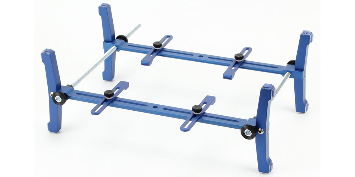
Bench Werx describes the PCB Rax system as an easy-to-use, versatile circuit board holder for board repair, prototyping, and assembly. The basic PCB Rax consists of two side rails with feet, connected by threaded rods that allow the rails to clamp rectangular circuit boards between them, plus four extension brackets that connect to the rails at adjustable angles to hold smaller or different shaped boards. Figure 1 shows these components assembled into the PCB Rax system, ready to hold a circuit board for assembly or rework.
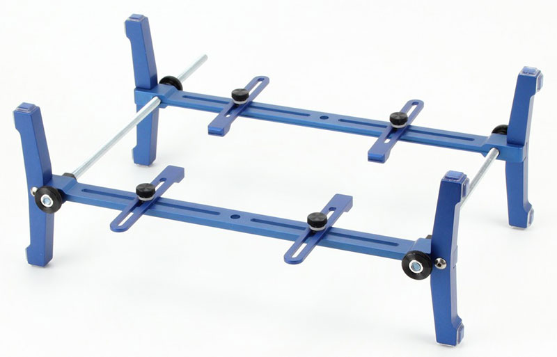
FIGURE 1. The PCB Rax system from Bench Werx.
To put the system through its paces, I assembled four circuit boards of varying size and complexity that I found lurking in my goody box. These included an Elenco SP-3B Solder Practice Kit (partially completed by the grandkids), an ancient Parallax S-2 Robot Badge kit, an old Pocket Mini Computer kit from Propellerpowered, and one Parallax EDU circuit overlay board that I used to build out a current project of mine. These boards are mostly through-hole construction with a few surface-mount components, and they have varying component densities and component proximity to board edges. They represent most of the PCB assembly tasks that I encounter as a hobbyist. I also placed a few components on an old prototype board, then removed and replaced them to simulate some board repair (Figure 2).
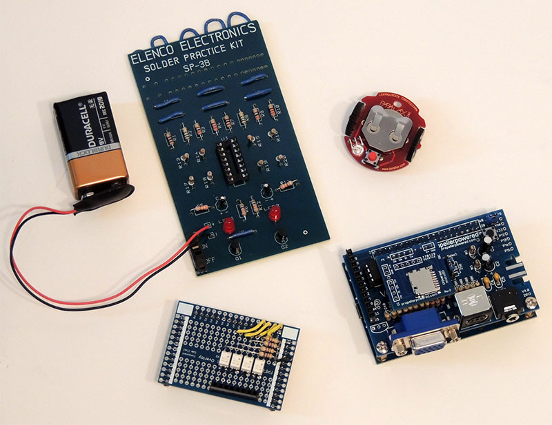
FIGURE 2. Projects completed for this evaluation. Note the different board sizes, shapes, and component densities.
To cut right to the chase, I’ve been building things electronic for a long time, and I was a bit skeptical that the PCB Rax could add much value to the process I’ve developed over the years. With my curiosity still intact, I spent about eight hours over six different sessions evaluating the system. I found it easy to learn and easy to use, and I discovered that circuit board assembly and repair went noticeably quicker and easier using the PCB Rax. I like this tool, and I’m going to order one. Here’s why.
With 50 plus years of hobbyist soldering under my belt, I’ve become something of a minimalist, now relying on tape, clips, and trained fingers to get the most out of my simple 15 watt iron. I no longer have a full-time electronics bench or even a soldering station, and I long ago traded in my big oscilloscope and signal generator for tiny PC-driven devices that hide in a desk drawer and see the light of day only occasionally. This minimalist approach has been working okay for me for some time. So, could the PCB Rax teach this old dog a new trick? It turns out it could, and did. The first thing you notice when unpacking the PCB Rax is the care with which it was packed. While not as fancy, it brought to mind the pride Apple and others display with their product packaging. The next thing you notice is the heft and finish of the PCB Rax. It is aircraft grade aluminum, anodized with a nice blue finish with quality fittings — top drawer, just asking for a place on your bench. So, could it make a difference in my hobbyist circuit board work?
Assembling the PCB Rax is straightforward and quick — just follow the excellent video instructions on the Bench Werx website. Once the system was assembled, I started with the Elenco SP-3B Solder Practice Kit, which is a 2-1/2” x 4” rectangular board with generous component spacing and areas to practice solder bridge avoidance and trace repair. Placing the board in the PCB Rax horizontally, I adjusted the extension backers to hold the board corners and tightened the tension knobs on the rails.
There are a lot of possible adjustments (important to the flexibility of the system) and it took me a few minutes to get the hang of things. I soon had the Elenco PCB held securely and was stuffing components and emulating board repair (Figure 3).
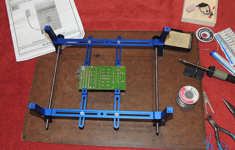
FIGURE 3. The Elenco Solder Practice Kit, with the PCB Rax in the horizontal position. This position was good for trace repair and (flipped over) component insertion.
At first, the system seemed only marginally better than my tried-and-true method of placing a single component, securing it with a small heatsink clamp, tacking one lead in place, then soldering all the leads — with all work done from the trace (underside) of the board. This required repeated flipping of the PCB Rax for each component, which the system supported nicely, but which didn’t seem to be any real improvement over my old non-PCB Rax method.
So, I positioned the system to hold the board vertically, tightening the tension knobs to make sure the PCB didn’t slip in the extension brackets. Now, I could stuff several components at once, then swing the PCB Rax around and solder them all in the same pass. The little heatsink clamp was still required to secure components, but now I was starting to see some benefits of the PCB Rax (Figure 4).
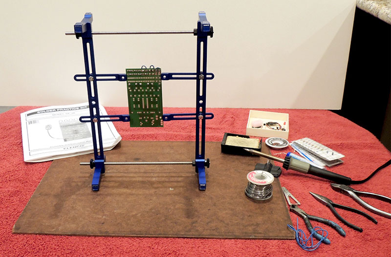
FIGURE 4. The Solder Practice Kit in the vertical position. This allows soldering multiple components in one pass and offers access to both sides of the board at once.
Next, I tackled the Parallax S-2 Robot Badge kit, which is a roughly circular PCB 1-1/2” in diameter with only three components. By now, I was getting comfortable with PCB Rax adjustments, but I was still surprised how easy it was to secure the small round board (Figure 5).
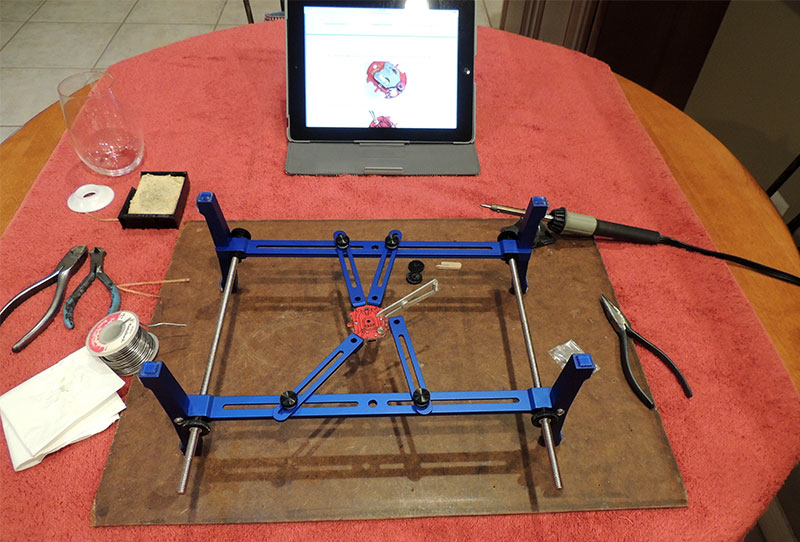
FIGURE 5. Assembly of the S-2 Robot Badge. Note the heatsink clamp holding a component in place for soldering.
This board was through-plated with nice lands on either side, and I learned that I could tack some components from the component side (using gravity to hold them in place instead of my heatsink clamp), then set the PCB Rax vertically and solder the whole lot. I was beginning to get a feel for this new system (Figure 6).
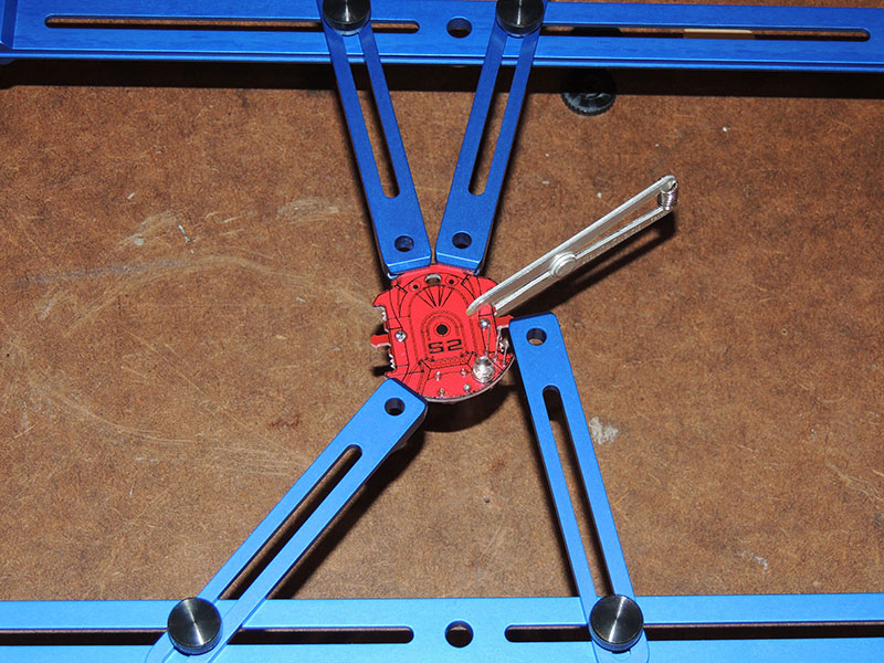
FIGURE 6. The PCB Rax extension brackets offer good positioning flexibility and easily held the small irregular-shaped Robot Badge PCB.
Having made short work of the Robot Badge kit, I decided to attempt an old Pocket Mini Computer (PMC) kit which consisted of a 2” x 3” “shield” for the Parallax QuickStart Board, with a 1” x 1” daughterboard on top. These boards were mostly through-hole with some surface-mount components, and component density was high with a number of headers and connectors at the board edges. These characteristics embody much of the PCB work I do, and I thought this kit would provide a “real” test of the PCB Rax. In addition, I had built several of these kits before using my tried-and-true method, which I thought should provide a good baseline for a “before and after” comparison of the system.
I started with the 2” x 3” shield board in the vertical position, and had no trouble soldering the discrete components and IC sockets. Some components needed my little heatsink clamp to steady them while soldering, but most didn’t, and things went smoothly.
This kit had several connectors on the board edges, and I had to jockey the extension brackets a few times to make room for the connectors being installed. Again, things went pretty smoothly, except for my over-confidence-driven haste (hey, I’m starting to get the hang of this!) that left a VGA connector slightly raised off the board on one side (Figure 7).
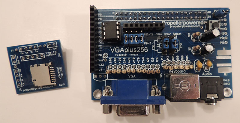
FIGURE 7. The completed PMC shield and daughterboard. The size, component density, and component proximity to the board edges are typical of many kits available today.
The 1” x 1” daughterboard required some surface-mount work, which meant the PCB Rax had to be in the horizontal position. To my mild surprise, the system held this tiny board securely, using only two of the extension brackets. It took some shifting around to get my iron positioned comfortably above the PCB Rax in the horizontal position (the feet stick up a couple of inches on each corner), but with my heatsink clamp holding things down, I was able to complete the necessary joints. I did have to remove the board, rotate it 90 degrees in the extension brackets, and re-tighten to get clear access to some of the joints. All in all, construction of this Pocket Mini Computer kit using the PCB Rax seemed easier and quicker than the several I had built previously using my old method (Figure 8).
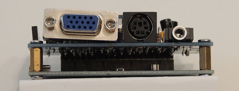
FIGURE 8. My sloppy installation of a VGA connector. I should have adjusted the extension brackets on the PCB Rax to give me more room.
My final PCB assembly test was a homebrew project built on a 1-1/2” x 2-1/4” Parallax EDU circuit overlay board which is a protoboard that can be used to create “shields” for the Amigo computer kit sold in the Nuts & Volts webstore. Unlike the three previous “kit” boards — where component x goes in position y — effective layout of the components on the protoboard is a big part of the build process.
I found that my new skills with the PCB Rax allowed me to quickly solder the male shield headers in place with the system set vertically. Then, I switched to the horizontal orientation with the component side of the board up, and dropped the various components into the protoboard, moving them around until I found a layout that I liked. Gravity held everything in place, and the PCB Rax elevation above my workspace allowed long component leads to stick out below the board with no ill effects.
With the board still horizontal, I tacked down the components I could, working easily from above and using gravity as my helper. I then turned the system vertically and soldered all the connections on the trace side of the board, using my little heatsink clamp to hold components I couldn’t tack from above. For me, the whole process was surprisingly intuitive — I now had a good “feel” for this new tool — and again my build seemed quicker and easier than it would have been using my old process (Figure 9).
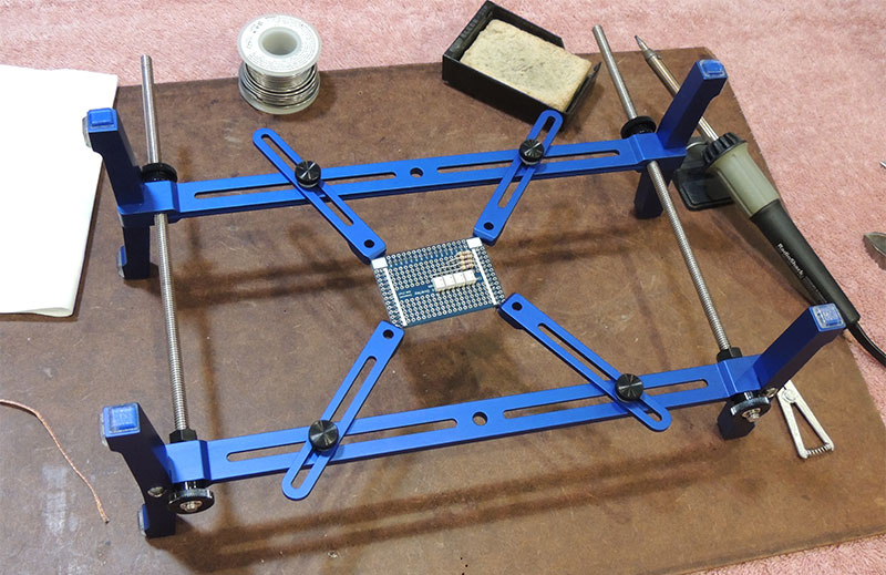
FIGURE 9. Arranging components on the EDU circuit overlay board. Once I had a layout I liked, I tacked things down as shown, then shifted the PCB Rax to the vertical position and soldered everything on the trace side of the board.
To complete my evaluation of the PCB Rax, I also simulated some board repair and rework by stuffing some components into an old prototype PCB (4” x 4”, from one of my projects), then removing and replacing them using the PCB Rax. The vertical positioning capability of the PCB Rax allows easy access to both sides of a board at the same time, which is very helpful for component removal — much easier than trying to hold your iron, needlenose pliers, and the board with just your two hands, no matter how skilled you are. If you do any amount of PCB repair, this feature alone should make PCB Rax a valuable addition to your workbench.
I also tried out a few interesting add-on components that will soon be available from Bench Werx for the system, including a center rail, alligator clips for the extension brackets, and some neat “third hand” articulated arms that fasten to the side rails. Depending on your needs, you may find that these significantly extend the capabilities of the system, and you should check them out if you’re considering PCB Rax.
Bottom line: The PCB Rax system from Bench Werx can securely hold almost any shape circuit board in either the horizontal or vertical position for project assembly or board repair. It is a high quality tool that should last for years, and I found it easy to learn and intuitive to use. For me, circuit board work seems noticeably easier and quicker using PCB Rax, enough so that I’m going to add one to my current “minimalist” tool suite.
If you do much circuit board assembly or protoboard work or if you just enjoy having the right quality tool for the job at hand, I suggest you take a close look at the PCB Rax. NV