Part 2 is available here.
The game of chess is considered by many to be very complicated and played by people who enjoy a challenge. Actually, the rules of how the chess pieces can move are fairly simple and easily learned. What makes things complicated is the total number of different ways a game can progress.
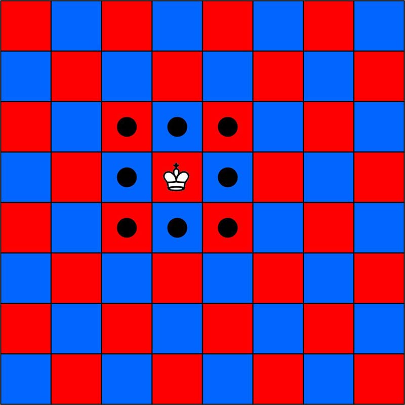
After each side has played three moves, the pieces could form any one of over nine million possible positions on the board. The number of distinct 40 move games is far greater than the number of electrons in the observable universe. If you're not familiar with chess, Wikipedia has an excellent introduction to the game at https://en.wikipedia.org/wiki/Chess. The chessboard layouts shown here illustrate the various allowable moves for each chess piece. The more esoteric castling, en passant, and promotion moves are not included in this project, although they could be added to the software.
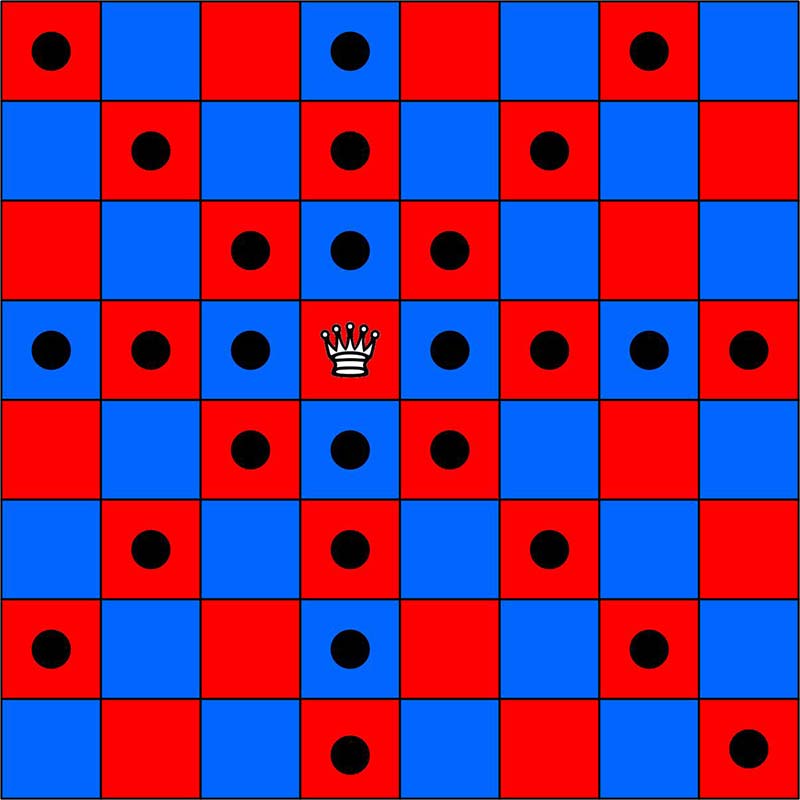
The black circles represent the squares where each piece can move. The knight is the only piece that can jump over other pieces. The pawn’s first move can be either one or two squares forward if those squares are empty. After the pawn’s first move, it can only move forward one square if empty. The X positions mark where the pawn can capture an opponent’s piece, which is limited to a diagonal move forward of one square.
King moves.
Queen moves.
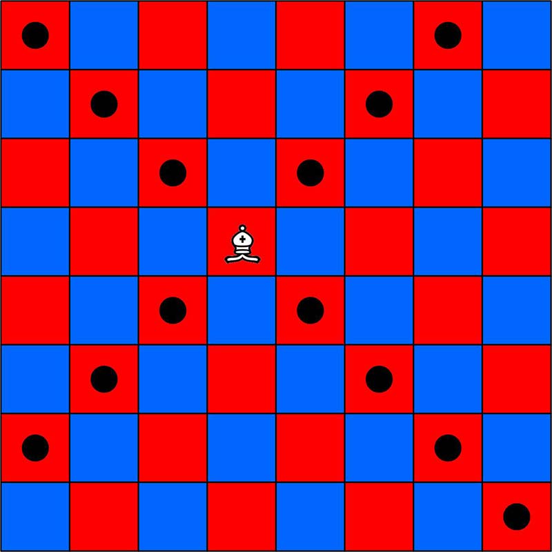
Bishop moves.
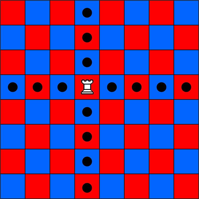
Rook moves.
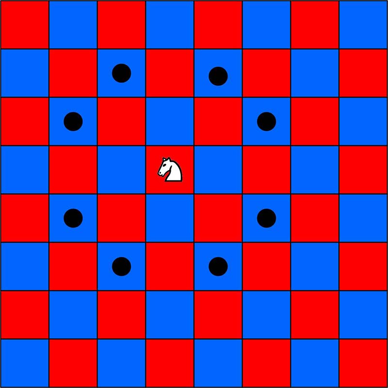
Knight moves.
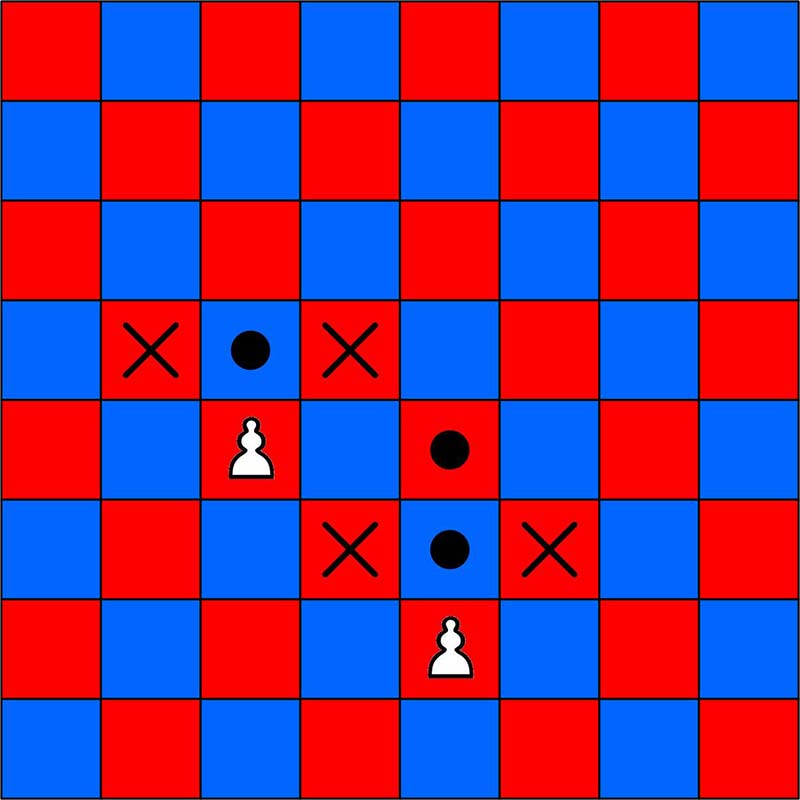
Pawn moves.
My Path to Building This
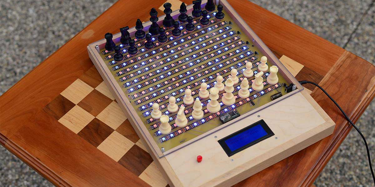
Some time back, my grandson mentioned a circuit board for gaming he was working on in his college program. Our discussion led me to thinking about building a chessboard using an array of RGB LEDs and some sort of detector to monitor the position of the chess pieces. I experimented with an array of 256 individual RGB LEDs placed in a 16x16 array, using a block of 2x2 LEDs for each board square. For the detector, I tried using reflective IR sensors.
After many attempts, I got a prototype to barely work. Scanning 256 LEDs is not simple, but worked fairly well. The problem was the IR detectors. Their output was read with an Arduino Mega 2560 analogRead() which gave differing values for each IR detector. This coupled with the fact that as the ambient light in the room changed, the IR detector’s values changed as well, it was just a matter of a few chess moves before the IR detectors gave an error.
After some experience using RGB LED strips, it occurred to me that this might be an easier way of driving the LEDs on an electronic chessboard. Once an LED is turned on, it doesn't need to be continually refreshed. My previous experience had me deciding against using IR detectors, so I went instead with Hall effect sensors.
The chess pieces have a small magnet in their base to trigger the Hall effect sensors. I also moved from using an Arduino Mega 2560 to a Teensy 3.1, which has more RAM and a 72 MHz clock, as opposed to 16 MHz for the Arduino. It can also be easily programmed with the Arduino GUI. You'll need to download and install the Teensyduino software package to program the Teensy 3.1 with the Arduino GUI. Download information and instructions can be found at https://www.pjrc.com/teensy/td_download.html.
| |
Arduino Mega 2560 |
Teensy 3.1 |
| RAM |
8K |
64K |
| Program Space |
256K |
256K |
| Clock Speed |
16 MHz |
72 MHz |
This chessboard does not play a chess game against you. The chessboard is used by two players, and the basic objective is to keep track of the board and the rules of the game for both players. This makes it a nice learning device for the beginning chess player. The LEDs light up to show a player where a piece can be moved, and whether there is an opponent’s piece that can be taken. Illegal moves are detected, as well as when the king is in check.
The chessboard operation does not include the three more esoteric moves — castling, en passant, and promotion — although these could be added. This project can be expanded on and if you're interested in chess programming, it has the potential to add intelligent responses or even game play. Teensy 3.1 pins 0, 1, 9, and 10, RX1, TX1, RX2, and TX2 were left unused and brought out to pads, allowing for an interface to a PC.
The hardware for this project is fairly minimal. The main cost was the printed circuit board (PCB). I designed mine using the free software available from ExpressPCB and then uploaded my design to them when ordering the boards. Their web address is https://www.expresspcb.com. This board is 11-1/2 x 11-1/2 inches. If you can make your own board, that will save you some money.
It might be possible to build the hardware on a breadboard of some sort, but it will take some effort with all the connections that are necessary. As for the software, it's already written and is available in the downloads.
What the circuit basically consists of is an 8x8 array of Hall effect switches that are scanned a row at a time. The results of this scan produce an 8x8 array indicating where the chess pieces are currently placed. Surrounding each Hall effect switch is a square of four RGB LEDs which represents a square on the chessboard. The LEDs are laid out and glued down as 16 strips that wind back and forth across the board.
Connections are also available on the board to optionally connect a four-line LCD display and a Real Time Clock (RTC) using an I2C interface. The LCD display has been incorporated in my software, but the RTC was not.
The Build
The schematic is shown in Figure 1. It's fairly large, so a full size file is available with the downloads.

FIGURE 1. Schematic of the complete chessboard circuit. (Full size schematic file is available in the downloads.)
There are two different versions of the PCB layout for an ExpressPCB board inthe downloads. The only difference is that one uses a standard DIP (Dual Inline Package) layout for the 74HTC138 and the other an SMT (Surface-Mount Technology) layout for this integrated circuit.
The RGB LED strips were laid out starting at the top of the PCB, alternately going left to right and then right to left as shown in Figure 2. This simplified the layout of the PCB, reducing the length of the traces between strips.
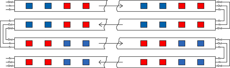
FIGURE 2. Layout of the first four RGB LED strips on the chessboard.
The RGB LED strips have adhesive on the bottom to attach them, and my first thought was just to stick them down on the PCB. Since these strips would be placed over various circuit board traces on the top of the board, I became concerned about creating a possible short on the PCB. I ended up gluing a strip of very thin tag board to the bottom of the RGB LED strips with Super Corona Dope™ from MG Chemicals, which is an excellent insulating varnish. The tag board surface was then glued down to the PCB with the Super Corona Dope. (Perhaps a little overkill, but it guaranteed no short circuits.) These strips are connected to the PCB by short pieces of wire soldered from the tabs on the LED strip to pads on the board.
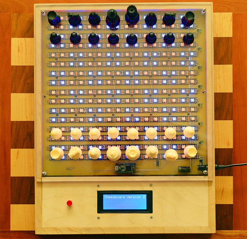
FIGURE 3. The circuit board mounted in a small wooden frame with the LCD display and restart switch.
There are two caveats when using these strips. I found that a short delay (I used one millisecond) was necessary between setting individual pixel colors. An example is in the colorSquare() function. Without this delay, the pixel color appears to be off by one position. This error was intermittent and the higher clock rate of the Teensy 3.1 may be the issue here. The other precaution I took with driving the RGB LED strip was not to drive the signal input directly from the Teensy 3.1 3.3 volt output. I placed a 7413 dual NAND Schmidt Trigger inline between the Teensy and the signal input. These are four input NANDs and because one will invert the signal, the two NAND gates were used is series. With this in place, the strip is driven by a five volt line.
The Teensy 3.1 was chosen because of its speed, adequate program space, and additional RAM, which is needed for the software that drives the chessboard. I elected to use an IC socket for the 28-pin Teensy 3.1, with the thought of ease of removal if the Teensy is damaged. Unsoldering a bad 28-pin IC is inviting damage to the PCB.
The Teensy 3.1 can be powered by a 3.7 to 5.5 volt source, but its I/O is at the 3.3 volt level. While this will interface directly with five volt ICs like the 7400 TTL and HTC series, it should be noted that its output will not directly drive a PNP transistor powered with five volts. This is because the 3.3 volt high output does not come close enough to the five volts to turn off a PNP transistor. The chessboard circuit has a five volt powered 74HCT138 three- to eight-bit decoder between the Teensy and the PNP transistors that power the rows of Hall effect sensors, which takes care of this problem. The 74HCT138 also reduces the number of I/O lines needed on the Teensy 3.1.
Allegro A3144 Hall effect sensors were chosen because they are inexpensive and readily available. They have a Schmidt trigger open collector output with a little hysteresis which gives noise-free switching when the magnet moves into or out of the field of the sensor.
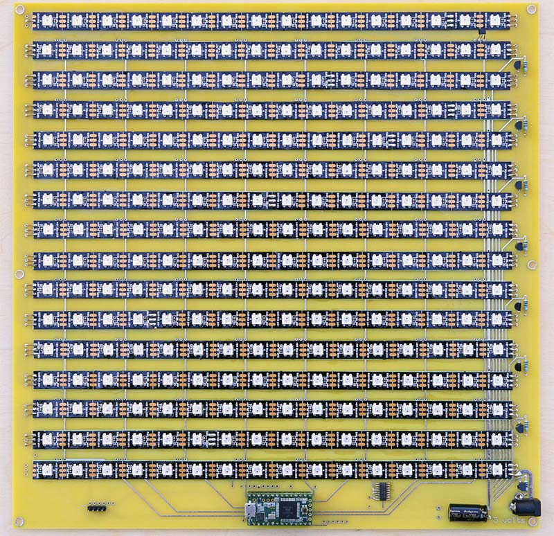
FIGURE 4. Prototype printed circuit board before installing the 64 Hall effect sensors.
Small neodymium disk magnets — 10 x 3 mm graded N50 — were glued into the bottom of a set of plastic chess pieces, with the correct magnet face placed at the bottom of the piece. I put together a single A3144 on a breadboard with an LED for output to determine the correct magnet face to place toward the A3144 to switch it on (see Figure 5).
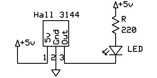
FIGURE 5. Hall effect test circuit.
The pins on the A3144 are bent at a right angle so that the face of the A3144 with the part number on it points upward when mounted on the PCB. Care needs to be taken to insure that the A3144 stands high enough off the circuit board to allow the magnet to switch this sensor; therefore, I used the full length of the A3144 leads.
I mounted a piece of 1/4 inch Plexiglas to the top of the circuit board using 5/8 inch spacers and 4-40 machine screws. I soldered in one A3144 to a height where I was confident the magnets in the bottom of the pieces would activate the A3144 through the Plexigas surface. The chess pieces sit on the Plexiglas with the LEDs underneath, representing the chessboard squares.
After mounting the single A3144, I cut a small strip of wood that just fit snugly under a row of the A3144s and taped it down with blue masking tape. This served as a jig when soldering in a row of A3144s such that they would all be the same height above the PCB (Figure 6). The A3144 has an open collector output and all the outputs of a column of eight are connected together. A row of A3144s is then powered by the PNP transistor and each column read one at a time by the Teensy 3.1.
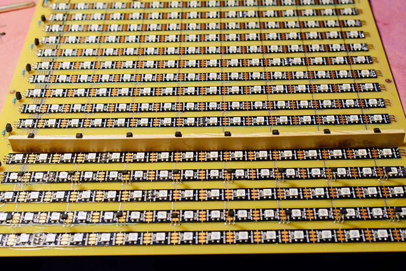
FIGURE 6. Wooden strip used to hold a row of A3144s in place for soldering.
The chess piece set I used was purchased from https://www.wholesalechess.com and is their Analysis Chess Pieces set. They are inexpensive and small; the king is 2-1/2 inches tall and the pawns are 1-1/4 inches, but are just the right size for our chessboard. The bottom has a 10 mm hole which perfectly fits a 10 mm diameter by 3 mm thick neodymium disk magnet. The magnets press-fit into the base of the chess pieces very easily. However, there is a problem — especially with the lightweight pawns.
When another piece gets near a pawn or you place a piece slightly off center, the magnets repel each other and you can unintentionally move a piece causing the chessboard to throw an error. My solution was to glue down thin cork disks to the bottom of the pawns creating a little friction. This keeps them from sliding away from other nearby pieces unless they are nearly touching. The pieces must be placed directly above the Hall effect sensors to work. A piece well off center will not be read by the sensor, causing an error.
Software
The first thing the program must do is turn on the LEDs to display a chessboard. This is made quite easy by using Adafruit’s Neopixel library to drive the RGB LED strip. For complete information on this library, visit Adafruit’s website at https://learn.adafruit.com/adafruit-neopixel-uberguide/arduino-library. All operations on LEDs will operate on squares of four LEDs. A little simple math is needed to go from one of the 8x8 positions on the board to the linear strip of 256 RGB LEDs.
The LEDs were mounted starting at the top of the board going left to right, with the next row going right to left, and then repeating eight times. This minimizes the length of the traces on the PCB that connects each row of LEDs. The colorSquare() function takes the x,y position of the square, its color, and whether it should be turned on immediately, and with a little math, turns on the four LEDs. Note that I went from using multiplication in my formulas to bit shifting, which is faster:
// Color an x,y square with a specific color
void colorSquare(byte x, byte y, uint32_t color, bool on)
{
if ((x >= 0) && (x < 8) && (y >= 0) && (y < 8)) // is it a legal square ?
{
int num1 = (y << 5) + (x << 1); // same as num1 = y * 32 + x * 2;
int num2 = num1 + 1;
int num3 = (y << 5) + 31 - (x << 1); // same as num3 = (y * 32 + 32) - (x * 2) - 1;
int num4 = num3 - 1;
// Needs a short delay, otherwise intermittent errors on position
pixels.setPixelColor(num1, color); delay(1);
pixels.setPixelColor(num2, color); delay(1);
pixels.setPixelColor(num3, color); delay(1);
pixels.setPixelColor(num4, color); delay(1);
if (on) pixels.show();
}
}
The colorSquare() function not only displays the standard chessboard layout, but by using other colors can show the correct positions that pieces can occupy with a move, or positions where pieces can be taken.
From here, a function is created that lights up all the LEDs in a chessboard array of blue and red:
// Color a chessboard with blue (for black) and red squares
void standBoard()
{
for (int y = 0; y < 4; y++)
{
for (int x = 0; x < 4; x++)
{
colorSquare(x * 2, y * 2, colors[RED], false);
colorSquare(x * 2 + 1, y * 2, colors[BLUE], false);
colorSquare(x * 2, y * 2 + 1, colors[BLUE], false);
colorSquare(x * 2 + 1, y * 2 + 1, colors[RED], false);
}
}
pixels.show();
}
Note that instead of turning on each square as it is created, we wait until all the squares have been set to their desired colors and then turn them on at once. This reduces flicker in the display:
// Color all squares, red for error alert, blue for checkmate
// Seems to work OK without a delay
void colorBoard(uint32_t color)
{
for (int i = 0; i < NUMPIXELS; i++)
{
pixels.setPixelColor(i, color);
}
pixels.show();
}
When an error occurs — like trying to make two moves in a row — the function colorBoard() is used to color the entire chessboard in red. No math is needed in this case. Each RGB LED is simply set to red using a 32-bit color code, and then turned on.
Writing the software to respond to moves on the chessboard is a challenge. After doing a little research on the Internet to make a decision on how best to represent the chessboard in a program, my impression was that there are as many ways to do this as there are programmers writing chess programs. The basic math structure chosen to represent the chessboard greatly affects how the program will operate on its data. Because many programs run on PCs (or even faster computers) that actually play chess, there is a push towards speed. With 64-bit computers, the match to the 64 squares on a chessboard works well, and “bitboard” structures are common.
A board representation called “0x88” might have been a better choice for my program. The name comes from the fact that ANDing hexadecimal 0x88 with a board location in this structure and getting a result that is not zero tells you if you are off the edge of the board. The code of the 0x88 structure is efficient and brief. However, it consists of a lot of bitwise operations. Reading the code using this structure is not intuitive and can be confusing — especially if you are not a seasoned programmer or are new to chess.
For ease in understanding the logic of my code, I selected 8x8 and 12x12 arrays of bytes to represent the chessboard, which helps visualization and keeps the math structure simple. This board representation may not be the most efficient, but I really wasn’t too concerned about speed since the chessboard is not going to look at all possible plays several moves ahead.
Due to the different sizes of the two different types of arrays, the program code does contain a large number of array indices that add a -2 or +2 to the index. Some of the worst bugs in my program code were simply due to forgetting this point.
There are two key arrays that represent the board. The first — which I label piecesVal[12][12] — identifies each piece and their placement on the board at startup. A second array — piecesValCur[12][12] — maintains the piece’s current positions and identifies each piece as they are moved. Various 8x8 arrays are used when reading the Hall effect sensors to determine where pieces are located.
Just about any set of numbers could be used to represent the different pieces. The 1 through 16 numbers I chose supposedly represent the relative values of the pieces. The number 128 was added to the byte value (bit 7 set) to indicate the white pieces. These values are placed in #define statements so the piece names can be used in place of the numbers:
// White = 128, white at bottom, starting positions// Black = 0, add color to piece value
//
// Black White
// Pawn = 1 and 129
// Knight = 3 131
// Bishop = 4 132
// Rook = 5 133
// Queen = 9 137
// King = 16 144
// Defines for chess pieces and spaces
#define BORDER 255
#define EMPTY 0
#define BLACK_PAWN 1
#define BLACK_KNIGHT 3
#define BLACK_BISHOP 4
#define BLACK_ROOK 5
#define BLACK_QUEEN 9
#define BLACK_KING 16
#define WHITE_PAWN 129
#define WHITE_KNIGHT 131
#define WHITE_BISHOP 132
#define WHITE_ROOK 133
#define WHITE_QUEEN 137
#define WHITE_KING 144
byte piecesVal[12][12]=
{{255, 255, 255, 255, 255, 255, 255, 255, 255, 255, 255, 255},
{255, 255, 255, 255, 255, 255, 255, 255, 255, 255, 255, 255},
{255, 255, 5, 3, 4, 9, 16, 4, 3, 5, 255, 255},
{255, 255, 1, 1, 1, 1, 1, 1, 1, 1, 255, 255},
{255, 255, 0, 0, 0, 0, 0, 0, 0, 0, 255, 255},
{255, 255, 0, 0, 0, 0, 0, 0, 0, 0, 255, 255},
{255, 255, 0, 0, 0, 0, 0, 0, 0, 0, 255, 255},
{255, 255, 0, 0, 0, 0, 0, 0, 0, 0, 255, 255},
{255, 255, 129, 129, 129, 129, 129, 129, 129, 129, 255, 255},
{255, 255, 133, 131, 132, 137, 144, 132, 131, 133, 255, 255},
{255, 255, 255, 255, 255, 255, 255, 255, 255, 255, 255, 255},
{255, 255, 255, 255, 255, 255, 255, 255, 255, 255, 255, 255}};
The 8x8 array is surrounded by two rows and columns of values set to 255 or 0xFF Hex. This boundary makes it a little easier to check for pieces moving off the board. The bank of two was necessary because a knight can jump two spaces over. So, for example, in code we could use:
if (piecesValCur[y][x]) == BORDER) // We are off the board in one comparison
instead of:
if ((y < 0) || (y > 7) || (x < 0) || (x > 7)) // We are off the board in possibly four comparisons
Instead of using numbers like 255 and 16 in the software, it is much more understandable to use the defines like BORDER and BLACK_KING. This has been done wherever possible in the software.
The piecesValCur[y][x] array contains not only the position using the indices, but the number values that identify the exact piece as well. However, when we read the Hall effect sensors, we will only get a reading that tells us where pieces are located — not their values. So, when reading the Hall effect sensors, we can find that position 3,4 has changed and there is not a piece there compared to a previous reading. We then use the 3,4 indices in the piecesValCur[y][x] array to find which exact piece was removed. Reading the Hall effect sensors gives us this array on startup:
byte piecesCurrent[8][8] = {{1, 1, 1, 1, 1, 1, 1, 1}, // [y][x] Where current piece are located
{1, 1, 1, 1, 1, 1, 1, 1},
{0, 0, 0, 0, 0, 0, 0, 0},
{0, 0, 0, 0, 0, 0, 0, 0},
{0, 0, 0, 0, 0, 0, 0, 0},
{0, 0, 0, 0, 0, 0, 0, 0},
{1, 1, 1, 1, 1, 1, 1, 1},
{1, 1, 1, 1, 1, 1, 1, 1}};
In addition to the piecesCurrent[y][x] array, similar arrays are maintained that are used when doing the actual reading of the Hall effect sensors. The two arrays are then compared to determine what piece has been moved. Notice that these arrays do not need the two rows and columns of additional values to denote positions off the board:
// Read a row of 8 Hall Effect sensors
int readLine(int row, byte piecesTemp[][8])
{
// Read each sensor in a row looking for a zero, which means a piece is there.
// The 3144 Hall Effect sensors are open collector output and pull to ground when activated.
// We invert the zero to place a one in our array if a piece is on a square.
// After each read we add to count to keep a running total.
int count = 0;
piecesTemp[row][0] = !digitalRead(2);
count += piecesTemp[row][0];
piecesTemp[row][1] = !digitalRead(3);
count += piecesTemp[row][1];
piecesTemp[row][2] = !digitalRead(4);
count += piecesTemp[row][2];
piecesTemp[row][3] = !digitalRead(5);
count += piecesTemp[row][3];
piecesTemp[row][4] = !digitalRead(6);
count += piecesTemp[row][4];
piecesTemp[row][5] = !digitalRead(7);
count += piecesTemp[row][5];
piecesTemp[row][6] = !digitalRead(8);
count += piecesTemp[row][6];
piecesTemp[row][7] = !digitalRead(12); // Oddball because we skipped 9, 10
count += piecesTemp[row][7]; // for serial RX, TX, Serial2 on Teensy 3.1
return count; // return number of pieces found in this row
}
// Read all 8 lines of the Hall Effect Sensors
int readHall(byte piecesTemp[][8])
{
// The function calls readLine() 8 times to read all 8 rows of Hall Effect sensors
// When finished piecesTemp[8][8] has positions of pieces on board
// Before each read we set the 3 bit address to the 74138
// The total number of pieces on the board is returned
int count = 0;
digitalWrite(A0, LOW);
digitalWrite(A1, LOW); digitalWrite(A2, LOW); // 000
delay(1); // let 3144 settle
count += readLine(0, piecesTemp);
digitalWrite(A0, HIGH); // 001
delay(1);
count += readLine(1, piecesTemp);
digitalWrite(A0, LOW); // 010
digitalWrite(A1, HIGH);
delay(1);
count += readLine(2, piecesTemp);
digitalWrite(A0, HIGH); // 011
delay(1);
count += readLine(3, piecesTemp);
digitalWrite(A0, LOW); // 100
digitalWrite(A1, LOW);
digitalWrite(A2, HIGH);
delay(1);
count += readLine(4, piecesTemp);
digitalWrite(A0, HIGH); // 101
delay(1);
count += readLine(5, piecesTemp);
digitalWrite(A0, LOW); // 110
digitalWrite(A1, HIGH);
delay(1);
count += readLine(6, piecesTemp);
digitalWrite(A0, HIGH); // 111
delay(1);
count += readLine(7, piecesTemp);
delay(100);
return count; // return count of all pieces on the board
}
It should be pointed out here that if you intentionally try to fool the Chessboard by doing something far outside the rules of chess, like picking up multiple pieces and switching them, it is not too hard to confuse the program or even lock it up. The software will do a good bit of checking to look for reasonable errors, but it cannot identify every trick you try. This should not present a problem if you simply stick to the rules of chess. This would not be the case if each piece could identify itself uniquely. For this it would be necessary to have something like an RFID tag on each chess piece and an RFID reader that could scan all 64 positions. A barcode reader might be another approach to this. The difficulty here is building a 64 position reader that will only detect and identify the piece above it.
When a piece is captured, the user should first remove the capturing piece, then remove the captured piece and then replace the capturing piece on the captured piece's square. If you use the capturing piece to slide or knock over the captured piece you will most likely get an error, which may not be recoverable, as the magnets can trigger other Hall Effect sensors.
If you try to take two turns in a row, or place a piece on a square which is not allowed, or make a move that places your king in check, all the LEDs on the board will turn red, indicating an illegal move. When you return the offending piece to its original position, the board will revert to blue and red squares and play can continue.
The functions readLine() and readHall() do the work of scanning the 64 board positions and creating an 8x8 array telling us where pieces are located, and also return the number of pieces found. The readLine() function scans a single row. Notice here that it would have been simpler to do a read of the D port pins 0-7 on the Teensy 3.1. In one line of code, we would have read all eight Hall effect sensors in one row. However, that would mean that we could not use pins 0 and 1 with our serial monitor.
In most of my projects, I try to leave these two pins unused by circuitry external to the microcontroller. Being able to use Serial.print() statements in your code to be read in real time using the embedded serial monitor in the Arduino GUI is a great aid in debugging code. Pins 9 and 10 were also left unconnected and brought out to pads on the PCB. This pair of pins implements RX2 and TX2 on the Teensy 3.1 and can be used to connect the chessboard to other external circuits or a PC.
Instead of a D port read, we use eight digitalRead() statements that are negated to read a single row of sensors. The Hall effect sensors are open collector, and when activated they read as a 0. So, for clarity, this is negated to a 1, representing a chess piece in that location.
The readHall() function calls readLine() eight times, after setting the three-bit address to the 74HCT138 to select each row. Here again, a port C output could have simplified things a little, but that could have interfered with the A4 (SDA) and A5 (SCL) I2C signals which are reserved for communicating with an LCD display or RTC. After the call to readHall(), the piecesTemp array will show the locations of all the pieces on the chessboard and return the total number of pieces found on the board.
At this point, all of the functions that interact with the hardware need to be described.
We'll pause here until Part 2. There will be an overview of the main sections of the software that contain the logic for supervising a chess game between two players. The loop() section of the program takes you through the first player's turn and then, on the next pass through, changes the turn to the second person. Inside the logic is the ability to detect which piece is lifted and display all its possible moves. There will also be some error checking and looking for a king in check or checkmate.
If you just can't wait, you can obtain the entire Arduino program from the download section. Keep in mind that this program is intended to run on a Teensy 3.1. NV
Parts List
Teensy 3.1 microcontroller
74HCT138 3 of 8 decoder
7414 dual Schmidt trigger
Allegro A3144 Hall effect sensors (64)
2N3906 PNP transistors (8)
470 ohm resistors (8)
2700 µF 6.3 volt electrolytic capacitor
0.1 µF disk capacitors (2)
Five volt/two amp power supply, wall wart type
Power jack to match power supply
LCD display, four-line/20 character with I2C two-wire interface
Momentary pushbutton switch
Programmable RGB LED strip, five meters, 60 LEDs per meter (You'll need 256 LEDs of the 300 LEDs in the strip.)
Printed circuit board
Insulating varnish like Super Corona Dope
Chess Piece set
Neodymium disk magnets, 10 mm diameter by 3 mm thick, grade N50 (32)
Miscellaneous header pins, four-pin header jumper cable, solid 22 gauge hookup wire, screws, nuts washers, spacers, wooden frame, 1/4 inch Plexiglas
Downloads
What’s in the zip?
Express PCB files
Schematic
Source Code