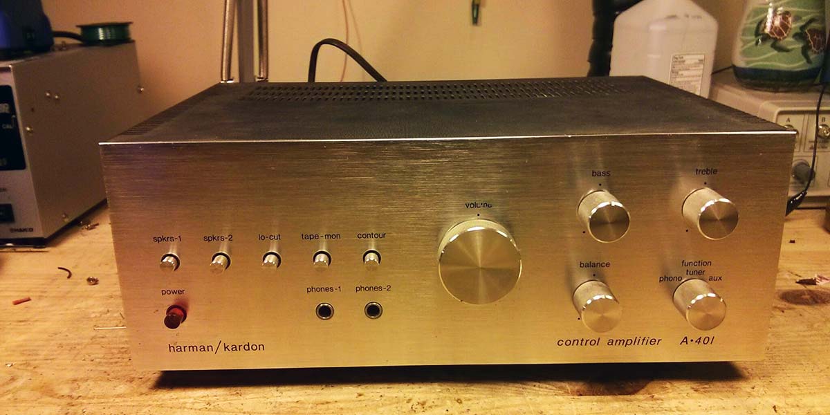
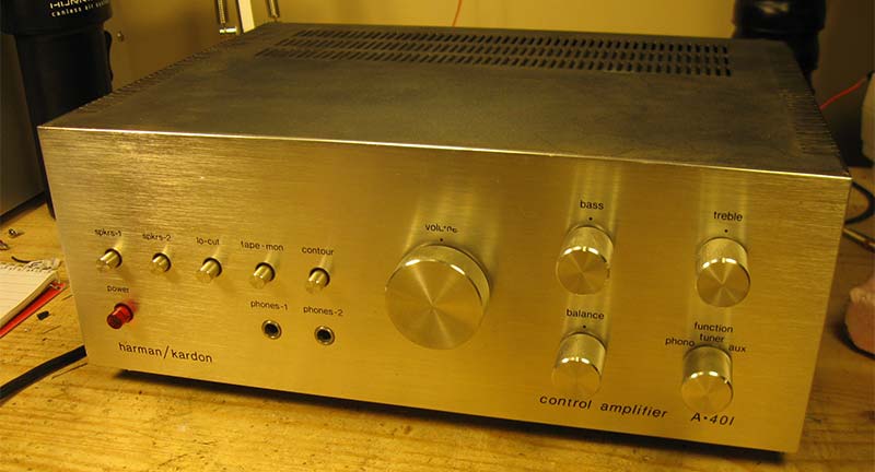
Vintage stereo equipment just has a special sound and presence unlike anything that's made today, and these pieces of hi-fi history are always worth preserving and restoring. I recently got to work on a classic from 1978: the Harman/Kardon A-401 stereophonic control amplifier.
I found this one nearly dead. It powered on, but that was about it. Both channels crackled and sputtered wildly, and barely any music made it from the inputs to the speakers — much longer and it would surely have suffered a catastrophic failure that destroyed it permanently.
This particular little amplifier offers 20W of power at less than 0.5% THD and is a great example of elegant understated styling from the late '70s. It's not the most powerful amp out there by any means, but it fits nicely in a room and has that classic hi-fi sound you just can't get with anything else.
Inside the Amplifier
The A-401 stereophonic control amplifier was designed in the USA and manufactured in Taiwan, and was designed with both sound and serviceability in mind which made it a real pleasure to work on. It features a pre-amplifier stage designed for a magnetic phono cartridge, tone controls, and quasi-complimentary output stage with a differential pair input to help keep distortion down.
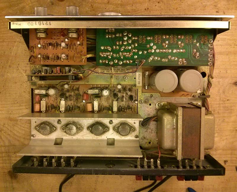
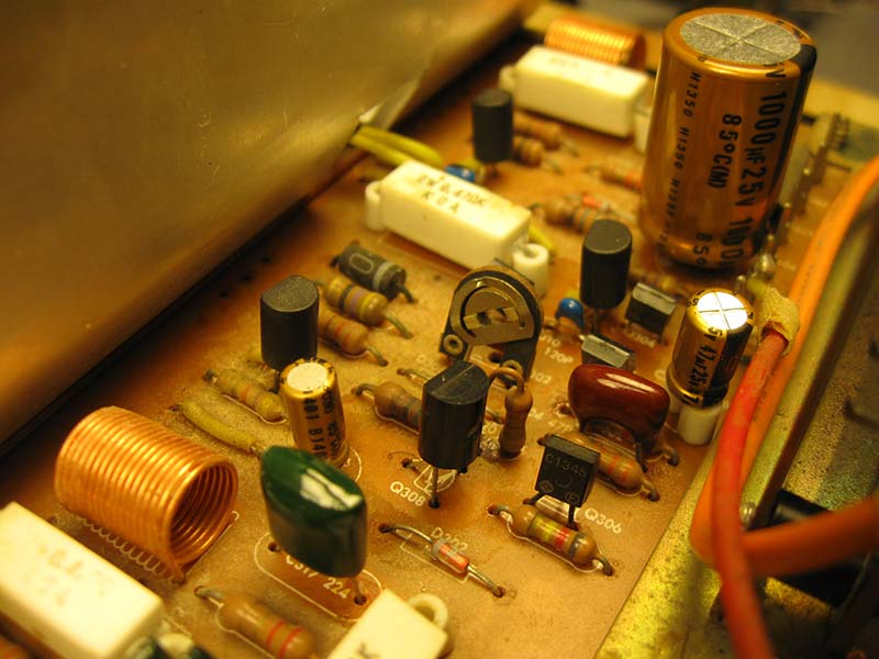
The dirty insides of this 38 year old amp
A quasi-complimentary output stage is a type of push-pull output stage made from two identical NPN transistors connected between the supply rails, in contrast to a fully complimentary output stage which uses a mirrored pair of a PNP and NPN transistors. Quasi-complimentary designs were popular in the early days of transistor amplifiers, when NPN power transistors were easier to manufacture than PNP power transistors, but continued to be found in lower powered and entry level amplifiers for many years. They're almost never used in modern construction as NPN and PNP power devices are equally available.
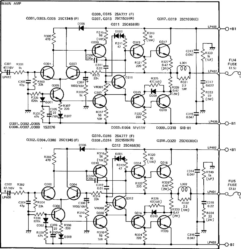
Partial schematic of the final amplifier board.
This one was fairly dirty inside and the 2SC1030 output transistors were badly corroded, but it survived in this condition for quite a while. This was a good example of Harman/Kardon not messing with a good thing, too: The phono amplifier board and final board show up in the model 430 receiver, and likely many others from around the same time.
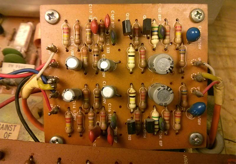
This phono amplifier PCB shows up in several other H/K amplifiers and receivers.
Except for the phono board, everything can be re-worked without even removing it from the chassis which made this one really easy. The first task was to shotgun replace all of the electrolytic capacitors on every circuit board. These capacitors start to dry out or leak with age — without fail — and can cause all kinds of havoc in the circuit.
Without known good capacitors in place, there's no point in doing any other work. I replaced all the small capacitors with Nichicon Fine Gold audio-grade capacitors — all de-rated for longevity — and Panasonic snap-in capacitors for the main power supply.
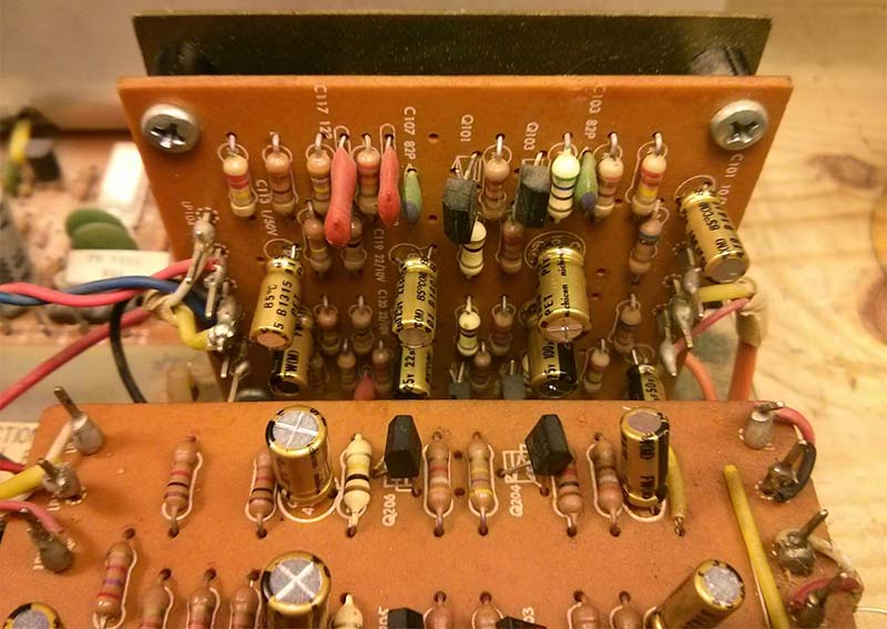
The tone and phono boards showing new Nichicon Fine Gold audio-grade electrolytic capacitors.
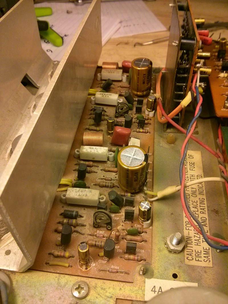
Showing the final power amplifier board with freshly replaced capacitors.
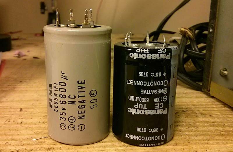
Components have come a long way in the last few decades! Left, the original snap-in capacitor; right, a drop-in replacement rated at three times the working voltage while still taking slightly less space.
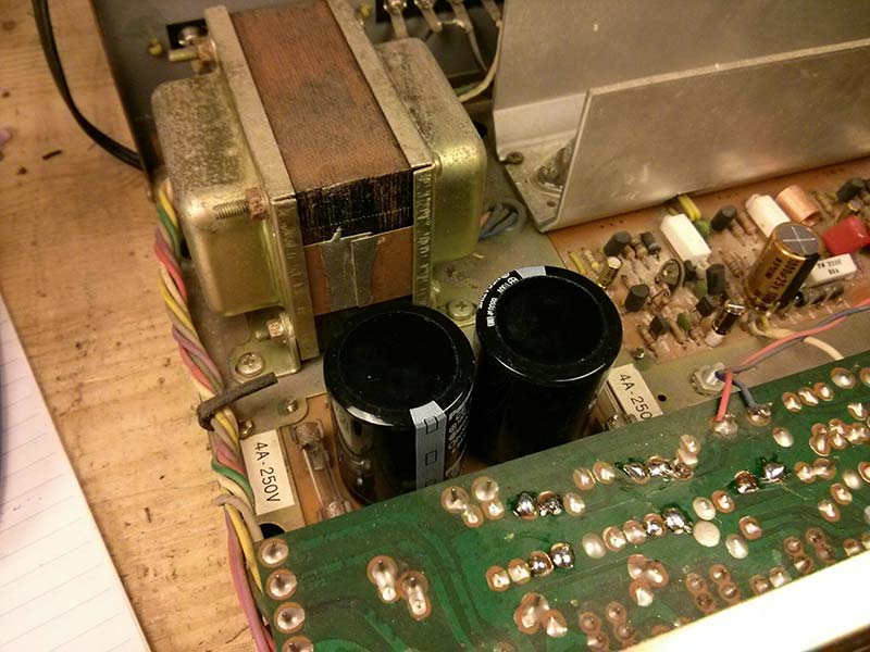
New capacitors installed on the power supply board.
It's tough to find exact replacements for some of the components used in these vintage amplifiers — especially filter capacitors. It's easy to find something that's electrically compatible, but it's pretty common for the physical layout to be just slightly wrong. For example, it's nearly impossible to find screw-terminal capacitors with 10 mm lead spacing, and 12.5 mm lead spacing just won't cut it.
Miraculously, 6,800 µF 100V capacitors from Panasonic were perfect drop-in replacements for the original Elna capacitors. They're physically very similarly sized, but the new ones are rated for 100V — about triple the original 35V rating. With such a significant de-rating, they should last for decades.
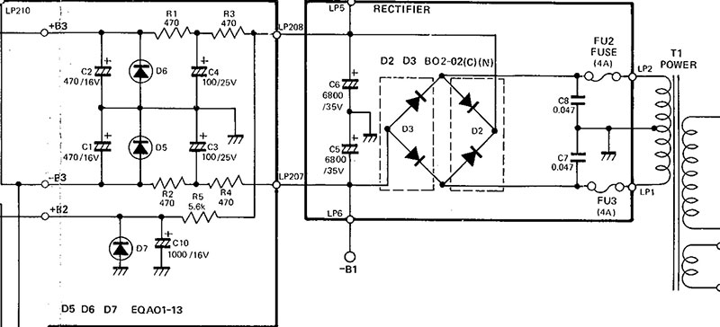
Partial schematic of the power supply.
The power supply in this amplifier is a bit simpler than you'd find in a bigger amp. While a larger one might use an active voltage regulator power supply, this one has a simple transformer, bridge rectifier, filter capacitors, and zener diodes for voltage regulation. It's simple but effective.
First Power-Up
After replacing all the electrolytic capacitors, it was time to power it up for the first time and see how it was feeling.
As with all electronics projects, take proper safety precautions while servicing a vintage stereo system. Don't do any work with the line cord connected — even if the unit is off — as power line leakage through the heating element of your iron could destroy transistors. Pay attention to unsafe vintage wiring schemes that may put mains voltage on exposed metal parts of the chassis, and keep in mind that some parts can get hot or might have exposed high voltages when operating. Be careful!
Ready for first power-up.
No smoke! One side was working great, but the other still had some issues. In addition to still sputtering badly when starting up, it was terribly distorted to the point of being almost unrecognizable. Time to drag out the oscilloscope and see what's going on! I followed the schematic to see where the signal was distorted. The tape out jack was my first step to see the output from the pre-amp stage.
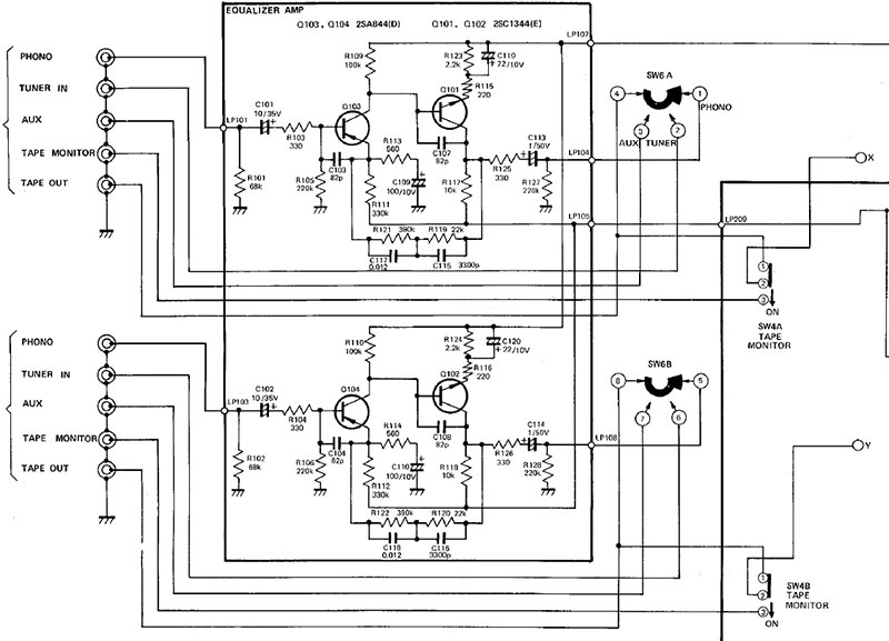
Partial schematic of the inputs and phono pre-amp.
Since I was using the tuner input — which doesn't go through the phono amplifier — there's only the switch between the tape output and the tuner input. As expected, everything was fine on the amp's front end. This meant the problem had to be in the final amplifier.
In a push-pull amplifier design, if the transistors aren't conducting evenly you'll hear the distortion audibly. I put the scope on the speaker terminals to see what the output signal was doing while playing some music, and it was showing a clearly one-sided trace, and only the highest peaks at that. This helped me narrow it down to the negative side of the push-pull circuit.
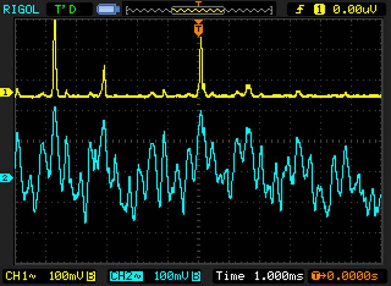
Oscilloscope trace showing the bad channel. Trace (1) showing the output of the defective side — only responding to high peaks and only in the positive direction, while trace (2) shows the other channel's correct output.
From the input to the final amplifier, I traced through the circuit using the oscilloscope until I found the point the signal became distorted. It turns out that Q8 — a 2SC1509 transistor for that side — was defective. It was conducting, but just barely. I pulled it and replaced it with a new old stock part, and that cleared the distortion right up. The sputtering and popping in that channel remained, though. Time for more digging!
Q8, the defective 2SC1509 transistor, center.
The Plot Thickens
While poking around with the oscilloscope to figure out where the noise was coming from, another problem unexpectedly developed: The fuses in the transformer secondary started blowing. That's very bad. It means something has developed a major short circuit and is drawing far too much current through the transformer secondary. Thinking it was a fluke or I'd touched something wrong, I replaced the fuses and fired it up again with all my probes removed. It lasted two or three seconds before popping again. Not good at all.
If the excessive current was drawn through the resistors in the low voltage section of the power supply, they'd have smoked immediately, but those resistors were all fine — this meant the failure was in the output transistors which are directly connected right after the transformer and bridge rectifier. I pulled them for inspection.
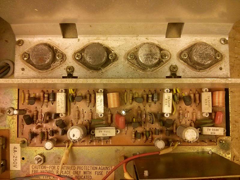
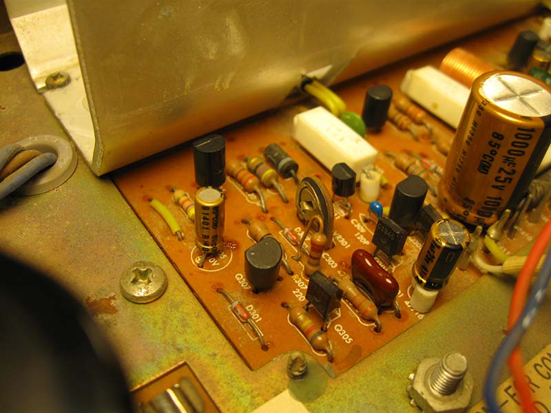
Close-up of the unmodified final amplifier board.
The transistors themselves all tested good — somehow — but the interesting part was their insulators. The collector of the 2SC1030 in this is tied to the metal case, mounted to a grounded heatsink. An insulator failure would short the collector (and supply rail) to ground, which is no good. As luck would have it, one of the mica insulators looked slightly cracked and had a carbonized trace on it. That'd be the problem, although it picked a weird time to show up.
I replaced all four mica insulators, applied new thermal grease, and for good measure I replaced the original 2SC1030 with all new ON Semiconductor MJ15003G transistors. These are drop-in substitutes, but like the capacitors are very de-rated in this application and should be reliable for a long time to come.
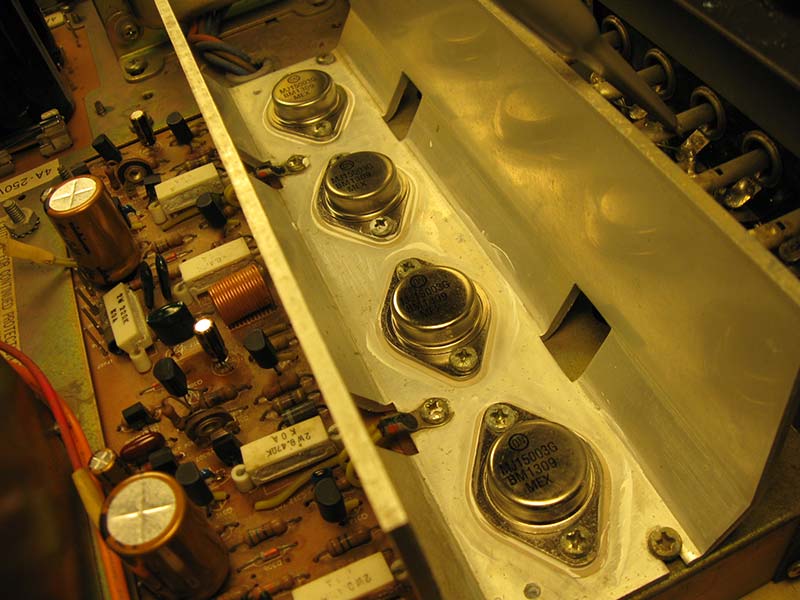
New ONSemi MJ15003G output transistors.
Back On Track
After I popped in new fuses again, the next power-up was stable and I was back where I'd started: one channel sounding great, but the other still showing a bit of sputtering and popping that just wasn't going away. It was worst at power-on and settled down a little over the next few minutes, but never disappeared entirely. Transients like that are a bit tough to track down using a scope since they're so quick. I traced forward from the input, stopping each time I saw spikes on the scope corresponding with pops in the speakers, and replaced them each one at a time. With each replacement, the noise cleared up a bit until it was completely gone. Three more transistors were bad: Q306, a 2SC1345; Q312, a 2SC458; and Q310, a 2SA777.
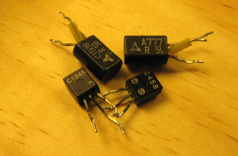
All four replaced small-signal transistors.
After the last replacement, I fired it back up and it sounded crisp and clean just like it should! Problem solved. Time to finish up!
Finishing Up
With the electrics sorted, it was time to go through final checks. This amplifier has a very simple design, so there's no power supply reference or DC offset adjustments to make; just the idle current adjustment across R329/R330 for 25 mV ±1 mV.
Bias-adjusting variable resistor.
Then, I ran some power curves. The combination of top-of-the-line audio grade electrolytic capacitors, new output transistors which are being run well below their maximum ratings, and good old fashion hi-fi design meant this one really shined. This little amplifier delivered below 0.1% THD through its rated power (20W) but continued to meet its power spec all the way to maximum output at 30W, while still staying below 0.5% THD.
This is pretty impressive — 50% more available power, and 1/5th the rated distortion through its factory power output. Vintage hi-fi amplifiers are often rated conservatively from the factory, but that's a significant improvement.
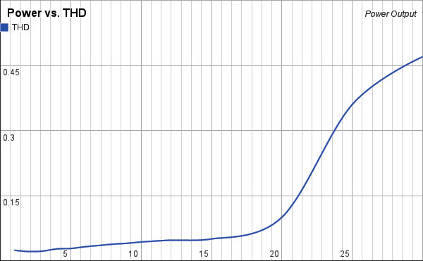
Power output vs. THD at 1 kHz into eight ohms.
With that, this H/K A-401 amplifier was ready for use as a daily driver at the heart of a nice little vintage stereo system. At only 30W/channel, it's not going to be setting any stereo competition records, but that's plenty of power for filling a room at a comfortable listening volume. It's got a great minimalist design, too, which makes it very attractive and definitely worth having fixed up.
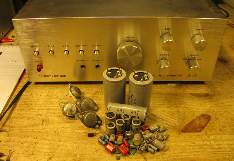
Out with the old, in with the new! Lots of replaced parts in this project.
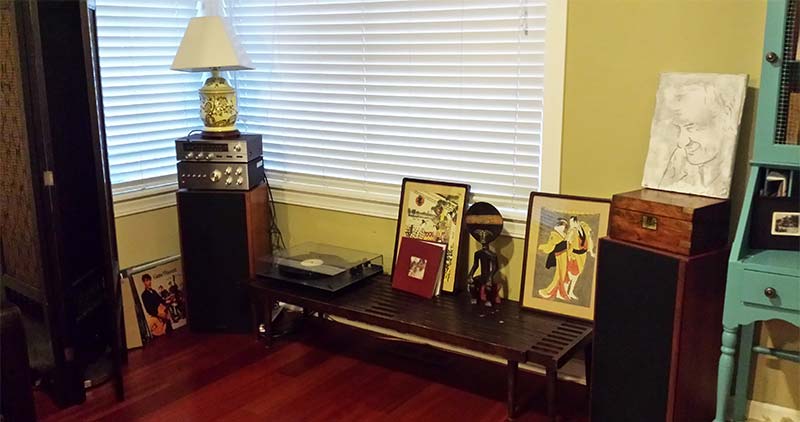
The A-401 back in its natural environment, powering a great little vintage system.
This was a pretty fun project which took some good troubleshooting. There was a defective driver transistor causing bad distortion, a failed insulator causing a dead short from the power supply, and three other intermittent small-signal transistors which were introducing noise into the signal path.
Vintage hi-fi repair is a fantastic hobby, and this project only took me about eight hours from start to finish. Replacing the electrolytic capacitors took about two hours, and the rest of the time was spent on slow and careful diagnostics through each stage. At the end, there's a beautiful functional silver front stereo amplifier to bring your music to life. Most vintage stereo repairs involve some detective work, but it's well worth it. NV