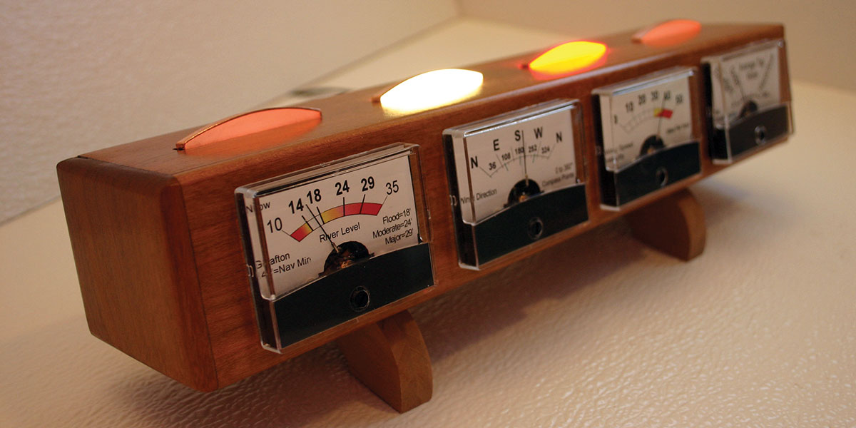
There is just something about a good ol’ analog panel meter that conveys trust in the value being presented. You can’t get much more reliable than a 50 uA panel meter connected to a DC shunt. If the needle was off zero, you just knew it was working. If the value wasn’t what you expected, a couple of taps on the faceplate would reassure you the value was true.
I will never forget the first time I worked with a panel meter. I was amazed at the simplicity and how customizing its placard made any project look professional. We could sure use some of this trust in the presentation of today’s IoT (Internet of Things) cloud based data.
Just because the days of a simple self-powered panel meter are long gone doesn’t mean we have to accept a displayed value as more or less accurate! So, I set out to connect an analog panel meter to the IoT and bring back the trust in the value displayed.
One of the advantages of having a value displayed on a physical analog panel meter is it only takes looking at it to read it. No finding your phone, opening an app, selecting the device, and loading its value. Simply glance across your desk and look. I wanted my IoT sourced panel meter to be true to that form. One glance is all it should take to know if the value being displayed is correct and within acceptable parameters (not too high or low). That turned out to be the real challenge to this project.
How can I convey trust that the value being displayed on the panel meter is valid with a quick glance? If it’s not valid, I need to give the user a simple way to “tap on the faceplate” and request valid data.
To do this, I added a marquee to the top of the panel meter’s box. The marquee is lit by a row of WS2812 color addressable LEDs. I can change the color and brightness of the marquee to represent different states of the data being displayed on the panel meter. This way, in one glance, the user can read the value of the panel meter and tell if the data is valid based on the marquee’s color. What if you’re not looking at the marquee and your data is not within acceptable parameters? Well, that one is simple. I added a little piezo buzzer for that with settable values for the audible alarm. To mute the alarm and request data updates (“tap on the meter face”), I put a little red button on the back of the box.
IoT SOURCED PANEL METER ARCHITECTURE
My panel meter is going to source its data from the IoT cloud (not a locally connected DC shunt), so I need to add a microcontroller and a radio. For that, I’m going to use the same hardware and software library as in my January 2016 Nuts & Volts article (SmartThings® and the Device Maker) that is based on the Parallax Propeller and Digi’s xBee ZigBee radio.
I want the panel meter to be generic in nature so it can be used to display values from just about any source: wind-speed, temperature, LUX, current, river level, and even the state of a door (open or closed). After all, since you can customize the meter’s placard, you can make the little needle measure anything.
Zigbee Clusters and Microcontroller Firmware
ZigBee clusters provide an application layer for device communications. They define how your device should communicate by detailing the radio’s data packet all the way down to the byte level. This may seem tedious, but by following the cluster’s specifications two completely independent vendors can make devices that communicate with each other. This allows your project to control or be controlled by other off-the-shelf ZigBee devices. This standardization is one of the reasons ZigBee is so popular in the home automation market.
All public ZigBee clusters are defined by the ZigBee® Alliance and you can freely download a ZigBee Cluster Library (ZCL) specification from the ZigBee.org website. The ZigBee Analog Output cluster number 0x000D just happens to be a perfect fit for the analog panel meter! It was designed for almost this exact purpose. A quote from the ZigBee Cluster library page 168 section 3.14.2.1 states, “The Analog Output (Basic) cluster provides an interface for setting the value of an analog output (typically to the environment) and accessing various characteristics of that value.”
A cluster’s definition will consist of a list of attributes and commands. Attributes are place holders for data and the type of data they contain. For example, our Analog Output Cluster (cluster number 0x000D) has an attribute called “PresentValue” (attribute number 0x0055) with the data type of single precision. So, if we write our code to listen for data at that attribute number, any device on the ZigBee network that adheres to the Analog Output cluster can control our meter’s needle.
PACKET DETAIL
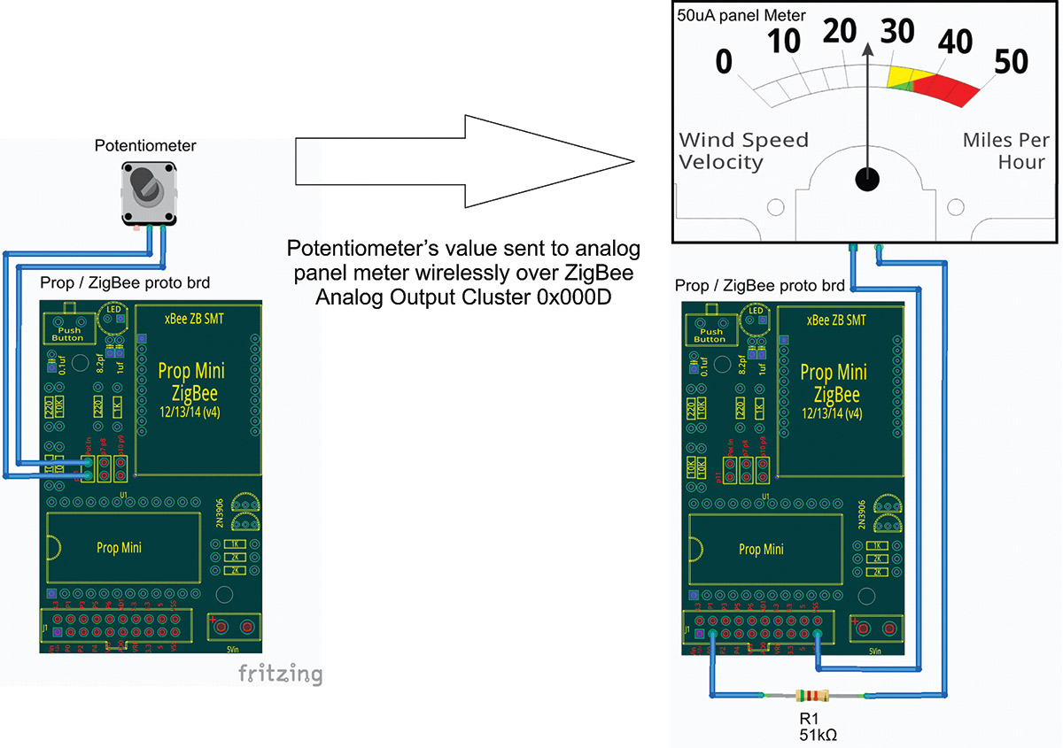
Say we have two wireless devices on our ZigBee network. The first device is a simple potentiometer connected to a microcontroller and a ZigBee radio (left side of Figure 1). The second device is a microcontroller connected to a ZigBee radio and an analog panel meter (right side of Figure 1).
FIGURE 1.
As the user turns the potentiometer, we want to send that analog value to the panel meter. Let’s assume the potentiometer is set halfway between its maximum and minimum value, and that represents the value of 25. How do we send the value of 25 to our panel meter? Let’s break it down.
We will have to communicate with the ZigBee radio in API mode to send the ZigBee cluster data. In this case, we are using Digi’s xBee ZB radios and will be using the format of an xBee Explicit Addressing Command frame (frame type 0x11) on page 146 of the ZigBee RF Modules User Guide.
The microcontroller on the left will send the following hex byte array to the xBee, to send the value 25 to the analog panel meter on the right:
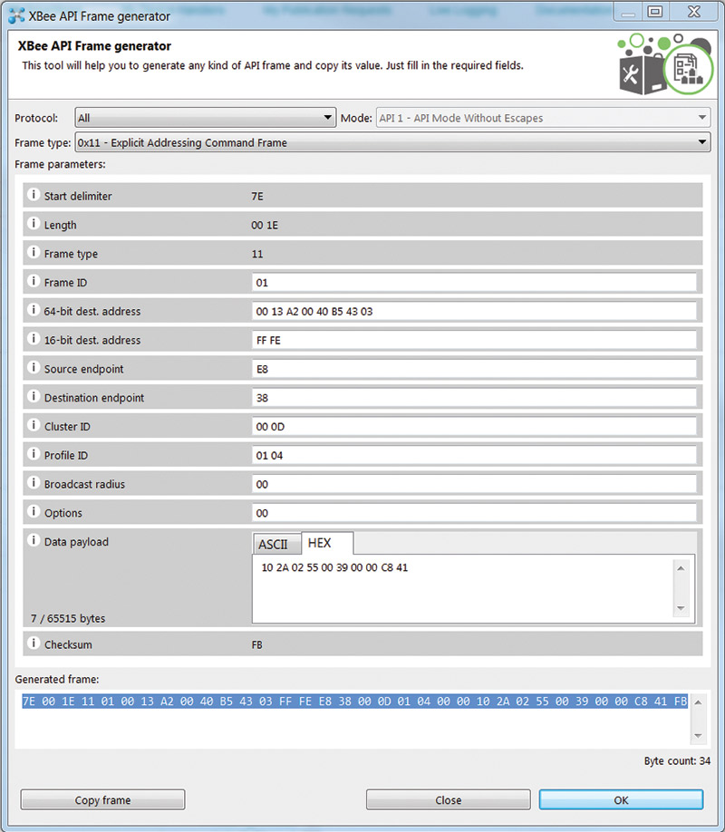
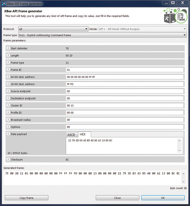
Let’s take a look at the above packet using Digi’s XCTU xBee API Frame generator shown in Figure 2.
FIGURE 2.
As you can see, most of the byte array consists of addressing fields that don’t change much from packet to packet. Take a look at the cluster ID and note that it is set to 0x000D (our analog output cluster number). Also note the destination endpoint number of 0x38. It gives us some very interesting features I will get back to later. If you take away the network and the application layer addressing parameters from the byte array, you’re left with just 10 bytes that make up the actual data payload (in [square brackets]):
These 10 bytes are defined in the cluster definition for the analog cluster 0x000D and they parse out as in Table 1.
Byte #
1
2
3
4
5
6
7
8
9
10
Data Payload
10
2A
02
55
00
39
00
00
C8
41
10 2A 02
Frame control header
See section 2.3.1.1 on page 14 of ZCL.
0x10 = Cluster wide command and disable default response.
0x2A = Transaction sequence number.
0x02 = Write attribute command; see section 2.4.3 on page 21 of ZCL.
55 00
Attribute to write in little-endian format
0x0055 = Present value (see Table 3.68 on page 168 of ZCL).
39
Data type
0x39 = Single precision floating point value will follow (see Table 2.16 on page 56 of ZCL).
00 00 C8 41
The value 25 as four-byte floating point in little-endian format
The hex number 0x0000C841 is in little-endian format; reverse the byte order to get 0x41C80000.
0x41C80000 is the IEEE 754 encoded value of 25.0 as a decimal.
TABLE 1.
The analog meter’s microcontroller will need to parse this data to pull out the 25.0 floating point value. To do this, I first parse out just the 10 byte data payload (the data payload mentioned above) from the xBee’s data packet into a byte array, then look at byte 3 to see what the command is for this packet. In this case, the command is 0x02 “write attribute” (see Table 2.9 on page 16 of the ZCL for a full list of command numbers). The two most common command numbers are 0x02 for the write attribute and 0x00 for the read attribute. So, now we know this is a write command and the next two bytes will be the attribute number to write.
In this case, it is 0x0055 and we know that attribute is the present value from our 0x000D cluster definition. I double-check that the data type value is correct and, if it is, I then convert bytes 7-10 to the correct endianness 0x41C80000 and store it in a floating point variable that equals 25.0. That variable is then passed to the method that drives the analog meter and sets the needle to the correct position.
ZigBee Destination Endpoints
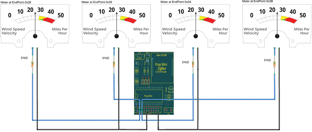
Now, let’s get back to that destination endpoint number 0x38. A ZigBee endpoint number along with the profile and cluster number give you application layer addressing. This allows you to direct a command to a specific component of your device. If we add three more analog panel meters to our microcontroller (giving us a total of four), we can assign each one a unique endpoint as shown in Figure 3. That is exactly how we send data to our four panel analog meter.
FIGURE 3.
Here is what the packets would like if we wanted to send the value 25 to all four meters at endpoints 0x38, 0x39, 0x3A, and 0x3B:
This gives each panel meter its own unique address, allowing any ZigBee device to send an analog value to a specific panel meter all on one microcontroller. So, if we had a third ZigBee device that was hooked up to a thermistor, it could send its temperature value to panel meter 2 by sending the packet to endpoint 0x39. You can have over 250 unique endpoints, so it is possible to hook up 250 analog panel meters to our microcontroller and address them all with unique endpoints. Of course, that’s not feasible with the microcontroller we are using here, but you can see the expansion potential by making our application endpoint addressable.
Another relationship can be drawn between an endpoint and a method within your firmware. Basically, endpoints give you unique addresses for methods within your microcontroller. Once I got my head around that it was a real ah-ha moment for me.
Vendor-Specific Attributes can be Customized to Your Device
As we discussed earlier, each cluster definition has a defined list of attributes that allow you to send and receive data (i.e., Attribute 0x0055 = present value). The cluster’s specification also sets aside a range of attribute numbers for “vendor-specific attributes.” Vendor-specific attributes allow you to build a custom solution on top of a standard cluster; it is up to you to document them or not. Often, vendors use these attributes and don’t document their usage. That is fine, as long as they are not using standard attribute numbers. You can do whatever you like with reserved attribute numbers. You can find these reserved numbers for the analog out cluster in Table 3.68 on page 169 of the ZCL. Cluster 0x000D has attributes from 0x0400 to 0xFFFF reserved for vendor-specific functions.
Since the goal of the four panel meter is to make it generic so it can display a floating point value that represents any type of data, we must be able to tune each meter. Let’s say meters 1 and 2 (end points 0x38, 0x39) are going to display wind speed, and their scale will range from 0 to 50 MPH. Meters 3 and 4 (end points 0x3A, 0x3B) are going to display temperature, and their scale will range from -15° to 120° Fahrenheit.
In order for our microcontroller to position the needle correctly on each meter, it needs to know what the meter’s minimum and maximum values are to calculate the position. These minimum and maximum values would fit perfectly in a custom attribute. Table 2 lists the attributes used by the four panel meter.
Attribute #
Description
Data Type
Data Description P55 of ZCL
Read/Write
Default
0x0055
Display current value
0x39
Floating point single precision
R/W
0
Custom Attributes
0x0400
Set marquee default color
0x23
Unsigned 32-bit integer
R/W
0x0E0600
0x0401
Set marquee default level
0x23
Unsigned 32-bit integer
R/W
200
0x0406
Meter min scale value
0x2B
Signed 32-bit integer
R/W
0
0x0407
Meter max scale value
0x2B
Signed 32-bit integer
R/W
50
0x0408
Meter max FRQ (set at factory)
0x23
Unsigned 32-bit integer
R/W
0x0500
Data time out in seconds
0x23
Unsigned 32-bit integer
R/W
0x0501
Low alarm value
0x2B
Signed 32-bit integer
R/W
-1
0x0502
Warning value (yellow light)
0x2B
Signed 32-bit integer
R/W
30
0x0503
High value (red light)
0x2B
Signed 32-bit integer
R/W
35
0x0504
Major alarm (flashing red light)
0x2B
Signed 32-bit integer
R/W
45
TABLE 2. Four Panel Meter Attribute Definition
Attributes 0x0406 and 0x0407 hold the min/max value for each meter. This allows us to programmatically change the configuration of our four panel meter. You can also see I used attributes 0x0500 to 0x0504 to set alarm values for each panel meter.
By making the alarm values settable via a custom attribute, it is now possible for users to easily change the value that will cause an alarm. For example, let’s say panel meter 4 is being used to monitor the water temperature of your pet’s outside heated water bowl. You could set the low alarm to go off when the value is below 32°F letting you know there is a danger of the water freezing over.
Come springtime, you move that probe to monitor the heat from a heat lamp pointed at your daughter’s baby chicks out in the garage. You now want to know if the low value ever drops below 80°F as that will be too cold for baby chicks. Since you can change the low alarm value per panel meter by updating custom attribute 0x0501, you can easily handle both applications all by sending one packet to update a custom attribute on that meter’s end point.
Tip: When I create a new device, I have found it really helps to define your custom attribute list early in the process. Not only do the attribute definitions make a good reference point for your program’s variables, I often take this table and cut and paste it into my device’s documentation.
Zigbee Network Layer Communications
Earlier I pointed out ZigBee clusters are the application layer for a ZigBee device. To get our IoT panel meter properly connected to a network, we need to focus a little on the network layer. The ZigBee Device Objects (ZDO) library is a collection of clusters for sending and receiving ZigBee network layer packets. Sending a ZDO cluster command is very similar to sending a ZCL command, but with two small changes.
To send a ZDO packet, you have to set your profile ID to 0x0000 and your destination endpoint to 0x00. This tells your radio to treat the data packet as a ZDO command. ZDO commands are extremely powerful. They allow you to bind devices together, create groups, check signal strength, read routing tables, and query devices for their capability. To be properly identified on a ZigBee network, our IoT panel meter needs to support at least three ZDO commands:
Device Announce (ZDO cluster 0x0013; see page 111 of ZDO spec). When a ZigBee device joins a ZigBee network, it needs to announce itself. This cluster is broadcast to all non-sleeping devices on the network letting them know it’s available to receive data. Often, a device announce will trigger an identification process from the ZigBee Coordinator (hub).
Active End Point Response (ZDO cluster 0x8005; see page 163 of ZDO spec). When the hub receives a device announce packet, it will send a ZDO cluster 0x0005 report active end point request. The IoT panel meter will listen for this request and respond with a list of its active end points by sending a ZDO Active End Point Response packet 0x8005.
Simple Descriptor Response (ZDO cluster 0x8004; see page 161 of ZDO spec). Once a list of endpoints has been received by the hub, it will then ask for details on each end point by sending a ZDO cluster 0x0004 report simple descriptor. The IoT panel meter will listen for this request and respond with the details for each end point in a ZDO cluster 0x8004 formatted packet. This packet will contain a list of clusters supported by that end point.
Table 3 shows what the ZDO packet exchange will look like when the IoT panel meter connects to the ZigBee network.
Four Panel Meter
Cluster
Cluster
Hub (ZigBee Coordinator)
Device Announce (broadcast)
0x0013
→
0x0005
Report Active End Points request
Active End Point Response
0x8005
→
0x0004
Simple Description Request for EP 0x38
Simple Description RPT for EP 0x38
0x8004
→
0x0004
Simple Description Request for EP 0x39
Simple Description RPT for EP 0x39
0x8004
→
0x0004
Simple Description Request for EP 0x3A
Simple Description RPT for EP 0x3A
0x8004
→
0x0004
Simple Description Request for EP 0x3B
Simple Description RPT for EP 0x3B
0x8004
→
TABLE 3.
After this exchange, the hub will know what this device is and how to communicate with it. This occurs every time the device is powered on.
This looks very similar to our previous ZCL packet, but take notice of the destination end point and Profile ID which are both set to 0, making this a ZDO command. Again, the real meat of this packet is the 12 bytes that make up the data payload in [square brackets] above. They parse out according to the ZDO cluster 0x0013 specification page 111, shown in Table 4.
Byte #
1
2
3
4
5
6
7
8
9
10
11
12
Data Payload
22
79
3D
03
43
B5
40
00
A2
13
00
8C
22
Sequence number
See section 2.4.2.8.1 on page 97 of ZDO specification.
79 3D
Network address
Two-byte little-endian
This is the four panel meter’s two-byte network address in little-endian format. It must be read from the xBee during your firmware boot process just after it joins the network as this address is dynamic and will change.
03 43 B5 40 00 A2 13 00
I3E Network address
Eight-byte little-endian
This is the IEEE address (MAC address) of the four panel meter's xBee.
8C
MAC capability flag field
See section 2.3.2.3.6 on page 83 of ZDO specification.
0x8C = b10001100 = Mains powered device; receiver on when idle; address not self-assigned.
TABLE 4.
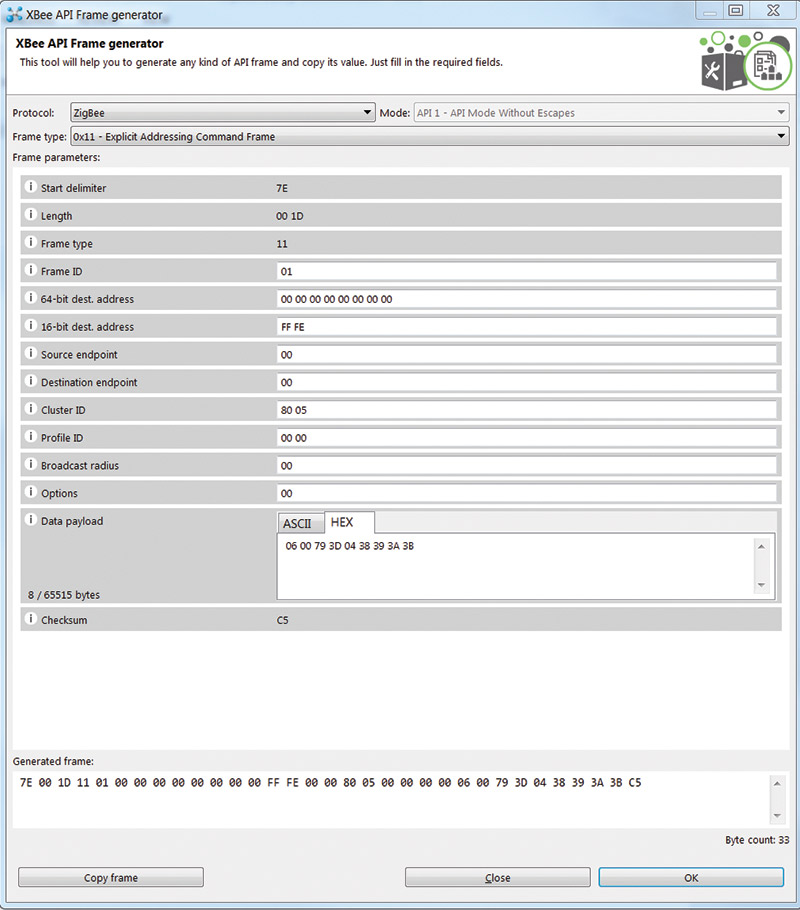
Active End Points Response Detail (ZDO cluster 0x8005)
Figure 5 shows the active end points report sent by the four panel meter in response to the report active end points request from the hub:
The breakdown of the active end point response data packet cluster parses out according to the ZDO cluster 0x8005 specification page 163, detailed in Table 5.
Byte #
1
2
3
4
5
6
7
8
9
Data Payload
06
00
79
3D
04
38
39
3A
3B
06
Sequence number
Sequence number should be set to match the sequence number of the requesting packet.
00
Status
00 = Success
79 3D
Network address
Two-byte little-endian
This is the four panel meter’s two-byte network address in little-endian format. It must be read from the xBee during your firmware boot process just after it joins the network as this address is dynamic and will change.
04
Active end points
The number of active end points on this device.
38 39 3A 3B
End point list
List the end point numbers supported by this device.
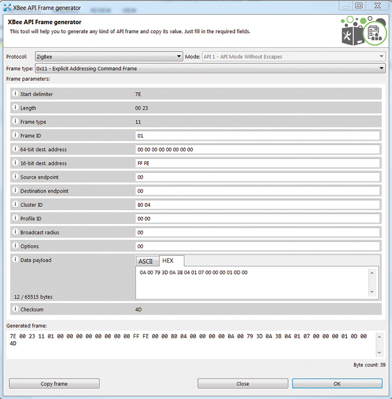
Figure 6 shows the packet details of the simple description report for end point 0x3B. This report is sent four times; once for each end point as requested by the hub:
The breakdown of the Simple Description report for end point 0x3B parses out according to the ZDO cluster 0x8004 specification page 161, detailed in Table 6.
Byte #
1
2
3
4
5
6
7
8
9
10
11
12
13
14
15
Data Payload
0A
00
79
3D
0A
3B
04
01
07
00
00
00
01
0D
00
0A
Sequence number
Sequence number should be set to match the sequence number of the requesting packet.
00
Status
00 = Success
79 3D
Network address
Two-byte little-endian
This is the four panel meter’s two-byte network address in little-endian format. It must be read from the xBee during your firmware boot process just after it joins the network as this address is dynamic and will change.
0A
Length
Length in bytes of the simple descriptor that follows.
3B
End point report
This is the end point being reported.
04 01
Profile ID
Application Profile ID in little-endian 0x0104 is the profile ID for home automation.
07 00
Device type
Device type ID in little-endian format 0x0007 = Combined Interface; see page 51 of ZigBee Home Automation Profile.
00
Version
App dev version number.
00
Input cluster count
This end point has zero input clusters.
01
Output cluster count
This end point has one output cluster.
0D 00
Output cluster number
This is the listing of output clusters for this end point in little-endian format. In this case, we only have one 0x000D (analog output cluster).
TABLE 6.
These are the most popular ZDO packets that your device will have to process. There will be other packets to bind your device to the hub, but for the most part the xBee ZB SMT radio will handle these automatically. At this point, the four panel meter is completely connected to the ZigBee network and properly identified. It is ready to start receiving data.
Accessing the Internet of Things
Up to this point, we have been displaying data from locally attached ZigBee devices. By connecting our four panel meter to a SmartThings® hub (ZigBee coordinator), we open up access to an Internet full of data via their online development environment. SmartThings is much like other home automation solutions on the market today in that they have a ZigBee hub that sits on your home network and connects to their cloud for control. Your smartphone connects to the SmartThings cloud to control the devices in your home.
What makes SmartThings unique is their cloud based integrated development environment (IDE) and the community of developers that work with it. The SmartThings IDE allows you to create custom device types and smart apps that can talk to your home automation devices.
If you create a custom device type or smart app, you can informally share them through GitHub.com or formally by going through the SmartThings certification process. Let’s take a closer look at the SmartThings IDE.
First of all, here are a couple of links you will want to spend some time at:
The documentation is good and getting better all the time. I encourage you to spend some time and read through it. The IDE allows you to build two types of applications: a “Device Handler” and “SmartApps.” We will start with the device handler. You can think of it as a device driver for our IoT panel meter. Its primary function is to communicate with a device and parse out data into a common format that can be manipulated and used by a SmartApp. SmartApps are usually small in size and are intended to connect devices to the physical world.
For example, say we want to send wind speed information to one of the meters on our IoT panel meter. A SmartApp will allow us to pick a source of that wind speed and the meter number to send it to. The SmartApp will then continue to run in the SmartThings cloud and when the data source is updated, an event will fire and send a new value to the IoT panel meter.
Building a SmartThings Device Handler for the Four Panel Meter
I want to start off by saying this is not intended to be a screenshot by screenshot tutorial for building a device handler. You should be familiar with what a device handler is (also referred to as a custom device type) and how to navigate around in the SmartThings IDE. A good place to start is with the device type developer guide; you can walk through the quick start.
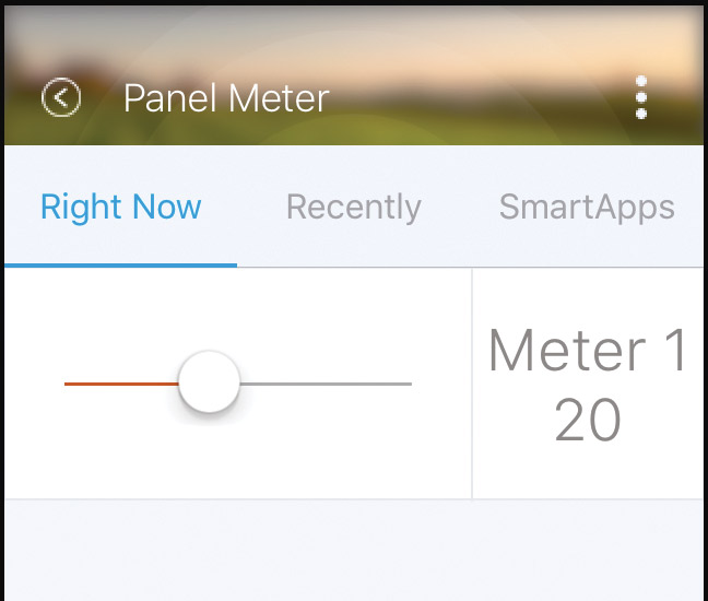
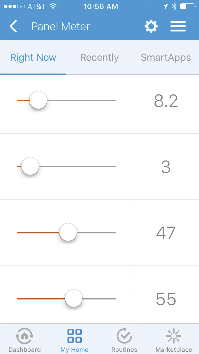
Here is a very simple SmartThings device handler for the four panel meter that will allow us to set the first meter’s value. As you can see in Figure 7, the interface is simple with a slider and a text box showing the value being displayed on meter 1 of the IoT panel meter.
FIGURE 7. Simple Panel Meter device handler.
When you slide your finger across the slider and remove it, the value of the slider will be sent to the IoT panel meter by sending a ZigBee write attribute command from the SmartThings hub. Here is the method from the SmartThings device handler that sends the slider’s value to the IoT panel meter:
private setMeter1Value(value){<br />
    // Send event to update SmartThings<br />
    sendEvent(name:”meter1_Value”, value: value<br />
    // Send to meter by writting value to<br />
    // attribute 0x0055<br />
    def endPointNumber = “0x38”         <br />
    def cluster =   “0x000D”            <br />
    def attribute = “0x0055”            <br />
    def dataType =    “0x39”            <br />
    def valueToSend = Integer.toHexString(Float.floatToRawIntBits(value as float))
The parameters for the st wattr command should look familiar. You can see it is passed an end point number, cluster number, attribute number, data type, and finally the value as a floating point. This command is sent from the cloud to the SmartThings hub on your local network and then out the ZigBee radio to our IoT panel meter’s network address.
This version of the device handler is a bit more complex than the single panel meter version. I not only added support for all four panel meters, but also added additional attributes and commands that will be used by SmartApps to send data to the IoT panel meter.
For the most part, this is a pretty standard SmartThings ZigBee device handler, but there are a couple of unique features I would like to focus on briefly.
At the beginning of this article, I discussed one of the attractions of an analog panel meter is the ability to tap on the faceplate to unstick the needle, verifying the displayed value is correct. To simulate this with our IoT panel meter, you push the red button on the back two times. This will cause the four panel meter’s firmware to trigger an update from the SmartThings device handler. The parse method in the device handler will send new values for each panel meter updating their value. This event is triggered in the device hander by reporting the value of 0x00 for attribute 0x0000.
One of the attributes I added to this full function device handler was “meterX_Timeout.” This attribute holds the time (in seconds) a panel meter will wait for new data (attribute 0x0500). Let’s say meter 1 is reporting wind speed and we expect the wind speed data to be updated at least every five minutes. By setting the meter1_Timeout = 300 seconds, we are actually setting a timer in the firmware of the IoT panel meter. Now, the firmware will count the seconds between data updates it receives for panel 1. If the time is higher than 300 seconds, it will start to pulse the marquee’s brightness letting us know the data is tardy for that panel meter.
So, now the IoT panel meter knows if the data being displayed is current and if it isn’t, it has a way to signal that to the user and request an update from the data source.
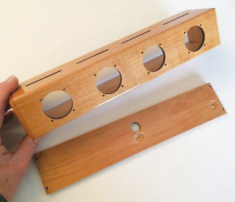
Cherry wood box assembled and ready for hardware.
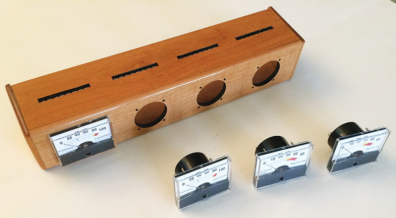
The IoT panel meter uses standard 50 µA analog meters.
Selecting Data to Display with a SmartApp
At this point, we have our IoT panel meter connected to our device handler, and we can use our smartphone to manually set the values for each panel meter. If we want to use something other than our finger to change the values of each panel meter, we need a SmartApp. SmartApps allow us to consume events that fire in the SmartThings cloud and act on them. For example, let’s say you have a temperature probe connected to your SmartThings hub. Every time a new temperature value is reported to the hub, an event fires within the SmartThings cloud. A SmartApp allows us to consume that event and do something with the value when it fires (is updated). That is how we grab data and send it to our IoT panel meter.
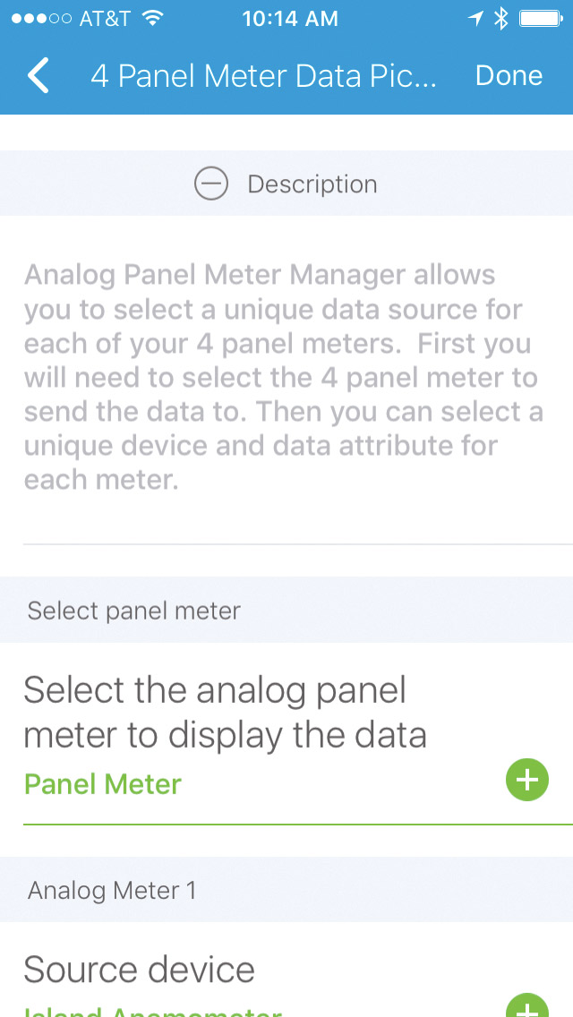
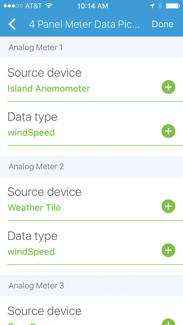
A good place to start with SmartApps is the online tutorial from SmartThings, “Writing Your First SmartApp.” They do a good job of illustrating how you select devices and subscribe to their events. Once you have a good understanding of what a SmartApp is, take a look at the IoT four panel meter data picker SmartApp code. Figure 9 and Figure 10 are screenshots from my smartphone to give you a feel for what the SmartApp looks like.
FIGURES 9 and 10. IoT four panel meter SmartApp smartphone screens.
As you can see, the SmartApp allows you to pick a panel meter to send the data to and data sources to pull the data from. The data source can be other ZigBee devices, Z-Wave devices, Wi-Fi devices connected to SmartThings, or even Internet hosted data in JSON format.
Hardware
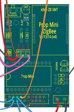
Figure 11 shows a Fritzing wiring diagram of my Prop Mini ZigBee prototype printed circuit board (PCB).
FIGURE 11.
This PCB is handy for prototyping ZigBee based projects as it takes care of all the wiring for the xBee radio and the Propeller Mini (see schematic in Figure 14). It also has some common components, like a couple of PNP transistors for level shifting, an RC network for measuring resistance, as well as a couple of pins pulled high for connection to external pushbuttons.
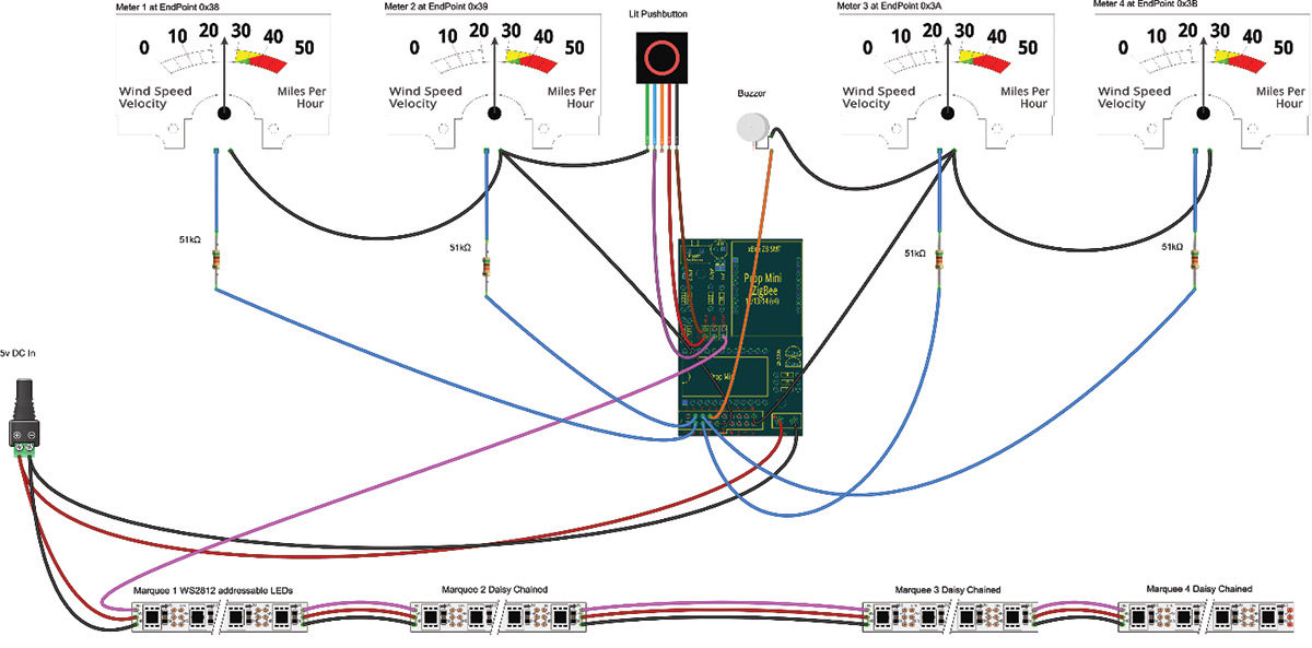
Figure 12 shows the connections for the four analog panel meters, four marquees, buzzer, and the lit pushbutton for the IoT sourced panel meter. The wires are soldered to the PCB making sturdy connections, allowing the whole thing to be tucked neatly into the wood box of the panel meter.
FIGURE 12. IoT connection diagram.
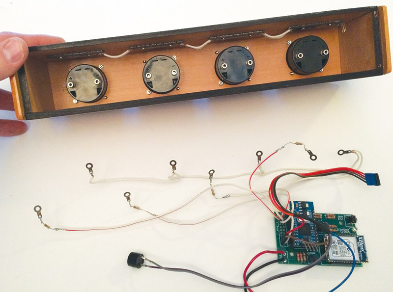
Figure 13 shows a picture of the Prop Mini ZigBee protoboard ready for connection to the analog panel meters and the marquees daisychained at the top of the wood box.
FIGURE 13. IoT Panel Meter from the back.
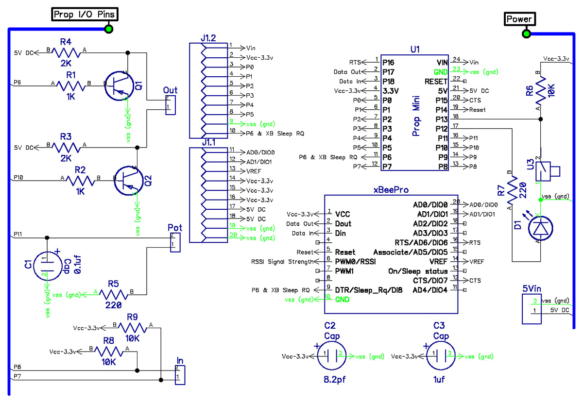
As mentioned, Figure 14 is a schematic of the Prop Mini ZigBee PCB.
FIGURE 14. Prop Mini ZigBee PCB schematic.
Note there are five headers on the board. The header at J1.1 and J1.2 has several general-purpose I/O pins as well as power. The header labeled “5Vin” is where you can connect a 5V DC power source.
Note this is connected to the 5V out of the Propeller Mini. This is okay as the Propeller will use the 5V to source its onboard 3.3V regulator.
The header labeled “Out” has the output of two PNP transistors that are driven by pings 9 and 10 of the Propeller. The header labeled “Pot” has an RC network connected to P11 and is where you can connect a photoresistor or other variable resistance to be read by the Propeller. Finally, the header labeled “In” has two 10K resistors pulling pins 8 and 7 high for connecting a pushbutton.
Microcontroller Firmware
As I mentioned earlier, the microcontroller I’m using for my IoT sourced panel meter is a Parallax Propeller. The firmware is written in Spin which is the Propeller’s native language. I have commented the code so it should be pretty self-explanatory if you’re an experienced Spin programmer. If not, Spin is similar to C+, so it shouldn’t be too difficult to get an idea of what is going on if you have a programming background.
The firmware for the Propeller can be found at the article link and at my GitHub site. Here, you will find several Spin object files and two Spin programs: PanelMeterSetup.spin and ZigBeePanelMeter.Spin. The PanelMeterSetup.spin program allows you to set up, test, and calibrate new meters.
Each panel meter will need to be calibrated once to make up for inaccuracies in the current-limiting resistor driving that panel meter.
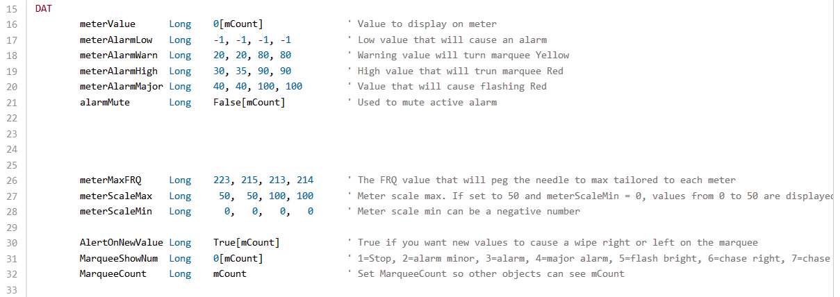
Load and run the PanelMeterSetup.spin program and follow the menu to calibrate each panel meter. This process will create new DAT settings for the meterMaxFRQ, meterScaleMax, and meterScaleMin variables as shown in the DAT section in Figure 15.
FIGURE 15.
Once you have the new calibration settings, you should update the values in the PanelMeter.spin object file and save the file with your new calibration settings. The PanelMeter.spin file is a Spin object that is used by both PanelMeterSetup.spin and ZigBeePanelMeter.Spin to drive the four panel meters.
Now that the calibration is complete, you can load the main program ZigBeePanelMeter.spin into the EEPROM of your Propeller Mini and boot it up. Connect the Parallax Serial Terminal (PST) to your Prop plug at 250,000 baud to see a running log of the boot process. The Prop Mini will boot up, connect to the xBee, and wait for the xBee to connect to your SmartThings hub. At this point, you should have already installed, saved, and “Publish for me” the “4-panel-meter” device handler (see the previous Building a Complete SmartThings Device Handler section).
To allow the Propeller Mini to join the SmartThings network, use your Smartphone and open the network for joining by adding a new device. Once the network has been opened for joining, you should see packets starting to flow in the PST log. The SmartThings cloud will identify the Propeller Mini as an IoT panel meter based on the footprint in the “4-panel-meter” device handler; it should appear on your smartphone. You can open the “ZigBeePanelMeter” on your smartphone and use your finger to change the slider for each analog panel meter. Verify the needle moves to the correct location on the meter face for the value selected.
Note: When a meter receives data, you will hear a soft click sound for each valid data packet and see the needle move.
If you haven’t done so already, the next step is to install the 4-panel-meter-data-picker.groovy SmartApp. Cut and paste the raw SmartApp file (at https://raw.githubusercontent.com/JohnRucker/IoT-Panel-Meter/master/smartapps/iot-panel-meter/4-panel-meter-data-picker.src/4-panel-meter-data-picker.groovy) into the SmartThings IDE (under the My SmartApps tab) and “Publish for me.” This app will allow you to select data sources for your IoT meter and can also be a template for future SmartApps. Please feel free to share your SmartApps with the SmartThings community as that is what makes SmartThings so unique. They have a very rich supportive online developer community.
I hope you find this information useful and I would enjoy hearing what you do with it! Please feel free to contact me on the SmartThings forum or in this article’s discussion page at the link provided. NV